EP0080997B1 - Device for the continuous casting of metals - Google Patents
Device for the continuous casting of metals Download PDFInfo
- Publication number
- EP0080997B1 EP0080997B1 EP82890174A EP82890174A EP0080997B1 EP 0080997 B1 EP0080997 B1 EP 0080997B1 EP 82890174 A EP82890174 A EP 82890174A EP 82890174 A EP82890174 A EP 82890174A EP 0080997 B1 EP0080997 B1 EP 0080997B1
- Authority
- EP
- European Patent Office
- Prior art keywords
- region
- nozzles
- openings
- slider plate
- plate
- Prior art date
- Legal status (The legal status is an assumption and is not a legal conclusion. Google has not performed a legal analysis and makes no representation as to the accuracy of the status listed.)
- Expired
Links
Images

Classifications
-
- B—PERFORMING OPERATIONS; TRANSPORTING
- B22—CASTING; POWDER METALLURGY
- B22D—CASTING OF METALS; CASTING OF OTHER SUBSTANCES BY THE SAME PROCESSES OR DEVICES
- B22D11/00—Continuous casting of metals, i.e. casting in indefinite lengths
- B22D11/04—Continuous casting of metals, i.e. casting in indefinite lengths into open-ended moulds
- B22D11/045—Continuous casting of metals, i.e. casting in indefinite lengths into open-ended moulds for horizontal casting
- B22D11/047—Means for joining tundish to mould
-
- B—PERFORMING OPERATIONS; TRANSPORTING
- B22—CASTING; POWDER METALLURGY
- B22D—CASTING OF METALS; CASTING OF OTHER SUBSTANCES BY THE SAME PROCESSES OR DEVICES
- B22D41/00—Casting melt-holding vessels, e.g. ladles, tundishes, cups or the like
- B22D41/14—Closures
- B22D41/22—Closures sliding-gate type, i.e. having a fixed plate and a movable plate in sliding contact with each other for selective registry of their openings
- B22D41/42—Features relating to gas injection
Definitions
- the present invention relates to a device for the horizontal continuous casting of metals, in particular steels.
- Such devices usually comprise a container holding the molten metal, which has in the lower region of its wall an outflow nozzle through which the metal flows into a substantially horizontally arranged mold, from which the metal strand is generally drawn off by mechanical means.
- An outflow channel is used to transfer the liquid metal from the container into the mold. in the form of a mouthpiece made in one piece with the container and made of refractory material which extends into the mold.
- such a device is described in FR-A-1 181 408, in which a container for the molten metal is connected via a vertical outflow opening to a horizontally arranged pouring channel with a subsequent horizontal mold.
- the heatable pouring channel located below the outflow opening has an opening on the side facing away from the casting mold and is for receiving a horizontally displaceable sealing plug which passes through this opening and which releases or closes the vertical outflow opening of the melt container and the pouring channel in the desired manner educated.
- the closure When the closure is open, the molten metal flows out of the melt container vertically and, with a sharp change in direction, flows into the horizontally arranged pouring channel and the subsequent continuous casting mold.
- the sealing plug which is adapted to the inner shape of the pouring channel, is inserted horizontally into the pouring channel and closes the opening between the melt container and the pouring channel and the pouring channel itself.
- shut-off device designed as a slide and having a horizontal slide plate as a closure element and also arranged in the vertical outflow channel.
- a porous part which essentially corresponds to the dimension of the discharge nozzle between the melt container and the mold and which, when the slide plate is in the closed position, is aligned with and fed by the discharge nozzle a gas can be supplied via a line.
- the gas is finely distributed in the porous part of the slide plate, keeps the molten metal constantly in motion in the form of rising bubbles and prevents it from penetrating into easily addable areas and parts of the slide. If the molten metal is hot and thin enough, an inert gas, such as Argon supplied, which ensures the desired displacement of the metal from sensitive areas of the slide.
- the system switches to the supply of oxygen or oxygen-containing gas, as a result of which the metal heats up in this area as a result of the oxidation of a small proportion of the metal and solidifies there is avoided by parts of the metal in the area of the movable slide plate.
- the supply of the gases does not cause any problems since, due to the horizontal arrangement of the slide plate and the surface of its porous gas supply part, the ferrostatic pressure of the metal located above the slide in the container is the same in all parts of the cross section of the outflow nozzle.
- the invention has for its object to provide a device for horizontal continuous casting, which comprises a closure member for interrupting the flow of cast metal, which is formed by a substantially vertically arranged slide, and in which to avoid disturbances in the region of the closure member Means for supplying inert or oxygen (containing) gas is provided.
- the invention relates to a device for the continuous casting of metals, in particular steels, which has a container for the molten metal to be cast, at least one outflow channel in the region of the bottom of the container in connection with at least one horizontal continuous casting mold and at least one outflow channel arranged in the channel
- Closure member comprises, and is characterized in that on the slide plate of an essentially horizontally guided outflow channel inclined to, essentially vertically, arranged slide on its side facing the melt container, in the region of the edge zone of the in the closed position of the slide plate the metal area to be cast in contact with the surface area and / or in the area of the opening tion, preferably bore, the head plate of the slide at least one opening or nozzle for supplying a gaseous medium, preferably oxygen and / or argon, is arranged with a tangential outflow direction.
- a gaseous medium preferably oxygen and / or argon
- a plurality of such openings or nozzles having such a tangential outflow direction are advantageously arranged at the specified positions of the slide plate and the top plate.
- These gas feeds can also be formed by capillaries, channels, nozzle openings or the like.
- tangential means that the gases on the one hand leave the respective surface of one of the parts of the closure element mentioned tangentially or at a flat or acute angle, and on the other hand that their outflow direction is essentially parallel to the corresponding part of the boundary line of the area to be flushed by the gas runs.
- the outflow direction although essentially tangential, can advantageously be directed outwards, ie against the periphery of the arrangement.
- the surface of the slide plate is preferably circular and has an edge boundary that is essentially parallel and tangential.
- the slide plate are arranged in pointed, preferably 3 to 45 degree, in particular 10 to 30 degree, angle penetrating openings or nozzles.
- this wall tangentially penetrating openings or nozzles with an obliquely directed towards the surface of the slide plate, preferably an angle of 3 to 75 ° , in particular from 10 to 60 °, including the outflow direction.
- the penetration of melt between the displaceable and firmly arranged parts of the closure member and the solidification of metal at these points are reliably switched off, even if the melt should have cooled too much.
- all openings or nozzles on the top plate and / or slide plate have outflow directions in the same direction. This causes a kind of spiral circular movement of the melt with a tendency away from the area of the slide.
- the openings or nozzles of the slide plate can all have the same direction of outflow and the openings of the nozzles in the top plate can also each have the same direction, but the flow direction of the gases on the slide plate is opposite.
- Another variant provides that adjacent openings or nozzles on the top plate and / or slide plate have outflow directions facing each other.
- An embodiment which has proven to be favorable for the uniformity of the gas supply over the cross-section to be purged and thus the metal movement in the entire area of the slide is that in the lower area, preferably in the lower half, of the surface area in contact with the molten metal Slider plate and / or in the lower region of the opening in the head plate are preferably arranged by 10 to 100% more openings or nozzles than in the upper region, preferably in the upper half, of the opening and / or of the surface region.
- a porous stopper which can be flowed through by at least one line and can flow through gaseous medium and is optionally only partially surrounded by the tangential outflow direction, is arranged.
- An embodiment has proven to be advantageous in which the openings or nozzles with the tangential outflow direction are arranged only in the edge zone of the lower region.
- the porous stopper can be arranged in an opening penetrating the slide plate, preferably a bore, or in a recess of the slide plate facing the molten metal.
- An embodiment variant is preferred in which a preferably cylindrically shaped recess extending into the region of the edge zone is arranged on the slide plate in its surface area in contact with the molten metal in the closed position, the boundary wall of openings or nozzles for feeding in gaseous media is penetrated with an essentially tangential and preferably directed against the molten metal outflow direction.
- the container 1 shown only partially in FIG. 1 for the molten metal 1 a to be cast has in its lower region a substantially horizontal outlet channel 2 connecting this container 1 to the horizontal, also only partially shown, continuous casting mold 4.
- a pressure cylinder plate slide 3 of which the top plate 10 and the divided slide plate 20 are shown enlarged.
- the fixed head plate 10 which is made of highly refractory material, is arranged facing the melt container and has a flow opening 11, the wall 12 of which is penetrated by the gas supply nozzles 13 having a tangential outflow direction.
- relatively more nozzles 13 were arranged than in the upper area 11 a. The gas emerging from these nozzles 13 continuously displaces the melt from the area of the slide plate 20.
- the displaceable slide plate 20 also made of refractory material, in the embodiment shown divided, is arranged, one part of which has a flow opening 20a which, when the slide 3 is in the open position, with the connecting channel 2 or the outflow nozzle and aligned with the bore 11 of the head plate 10.
- the tangentially opening nozzles 23 are arranged in its peripheral or edge zone area are supplied with the pressurized flushing or oxidizing gas via an annular channel 28. The gas flowing out tangentially keeps the melt in the area of the slide plate 10 in motion and continuously displaces it from the area thereof.
- the front view shown in FIG. 2 of a part of the slide plate 20 shows the region 22 which is delimited by an interrupted circular line 22b and which is in contact with the molten metal 1a when the slide plate 20 is in the closed position or from its corresponding part.
- the outflow openings of the nozzle 23 for the tangential supply of the gases are arranged in the edge zone 22a of this region 22.
- more tangential nozzles are arranged in the lower region 22c than in the upper region 22d. This results in a particularly good compensation for the differences in the ferrostatic pressure occurring over the cross section of the horizontal outflow channel 2 (FIG. 1) and thus a uniform flushing of the sensitive area of the slide.
- a porous stopper 25 (shown in dash-dot lines) seated in a recess of the slide plate 20 can be provided, from the center of the area 22 and surrounded by the nozzle openings 23, from which, also fed by Broken lines indicated supply line 27, the gases are introduced into the molten metal 1 over a large area and very finely distributed.
- the porous stopper 25 is also arranged in the upper partial region 22d of the slide 20, but there are no gas supply nozzles with an essentially tangential outflow direction arranged in this upper part; the porous stopper 25, for example made of zirconium oxide, takes on their task.
- the gas supply nozzles 23, which are essential to the invention and have a tangential outflow direction, are arranged in the lower region 22c, so that even with this embodiment variant, uniform flushing of the overall cross section is ensured despite the vertical arrangement of the slide plate.
- FIG 5 shows the section 22 of the slide plate 20 of another preferred embodiment of the device according to the invention, which is in contact with the melt 1 a in the closed position, in section.
- the gaseous medium is supplied via the ring channel 28 and the nozzles 23 penetrating tangentially through the cylindrical boundary wall 24a of the recess 24 in the slide plate 20.
- the boundary wall 24a of the recess 24 is located in the area of the edge zone 22a of the area 22 which is in contact with the molten metal 1 when the slide plate 20 is in the closed position, so that in this embodiment as well, the effect according to the invention of flushing the sensitive zones of the slide with gas is achieved.
- the slide plate 20 can be provided in a completely analogous manner.
Landscapes
- Engineering & Computer Science (AREA)
- Mechanical Engineering (AREA)
- Casting Support Devices, Ladles, And Melt Control Thereby (AREA)
- Furnace Charging Or Discharging (AREA)
- Continuous Casting (AREA)
Description
Die vorliegende Erfindung betrifft eine Vorrichtung zum horizontalen Stranggiessen von Metallen, insbesondere Stählen.The present invention relates to a device for the horizontal continuous casting of metals, in particular steels.
Derartige Vorrichtungen umfassen üblicherweise einen das schmelzflüssige Metall aufnehmenden Behälter, der im unteren Bereich seiner Wandung eine Ausflussdüse aufweist, durch die das Metall in eine im wesentlichen horizontal angeordnete Kokille fliesst, aus der der Metallstrang im allgemeinen mit mechanischen Mitteln abgezogen wird. Zur Überleitung des flüssigen Metalls aus dem Behälter in die Kokille dient ein Ausflusskanal, derz.B. in Form eines mit dem Behälter einstückig ausgebildeten Mundstückes aus feuerfestem Werkstoff, das in die Kokille hineinreicht, ausgebildet sein kann.Such devices usually comprise a container holding the molten metal, which has in the lower region of its wall an outflow nozzle through which the metal flows into a substantially horizontally arranged mold, from which the metal strand is generally drawn off by mechanical means. An outflow channel is used to transfer the liquid metal from the container into the mold. in the form of a mouthpiece made in one piece with the container and made of refractory material which extends into the mold.
In der Praxis ist es beim kontinuierlichen horizontalen Stranggiessen manchmal notwendig oder erwünscht, den Giessvorgang rasch zu unterbrechen, um beispielsweise beim Übergang zu einem anderen Erzeugnis die Kokille bei mit Metall gefülltem Behälter auswechseln oder an dieser Reparaturarbeiten vornehmen zu können.In practice, in continuous horizontal continuous casting, it is sometimes necessary or desirable to interrupt the casting process quickly, for example in order to change the mold when the container is filled with metal or to be able to carry out repair work on it when changing to another product.
So ist beispielsweise in der FR-A-1 181 408 eine derartige Vorrichtung beschrieben, bei der ein Behälter für das geschmolzene Metall über eine vertikale Ausflussöffnung mit einem horizontal angeordneten Giesskanal mit anschliessender Horizontal-Kokille verbunden ist. Der unterhalb der Ausflussöffnung liegende beheizbare Giesskanal weist auf der der Giesskokille abgewandten Seite eine Öffnung auf und ist für die Aufnahme eines durch diese Öffnung geführten horizontal verschieblichen, die vertikale Ausflussöffnung des Schmelze-Behälters und den Giesskanal jeweils in gewünschter Weise freigebenden oder verschliessenden Verschluss-Stopfens ausgebildet. Bei geöffnetem Verschluss fliesst die Metallschmelze vertikal aus dem Schmelze-Behälter aus und unter scharfer Richtungsänderung in den horizontal angeordneten Giesskanal und die anschliessende Stranggiess-Kokille ein. Soll der Metallfluss unterbrochen werden, wird der der Innenform des Giesskanals angepasste Verschluss-Stopfen horizontal in den Giesskanal eingeschoben und verschliesst die Öffnung zwischen Schmelze-Behälter und Giesskanal sowie den Giesskanal selbst.For example, such a device is described in FR-A-1 181 408, in which a container for the molten metal is connected via a vertical outflow opening to a horizontally arranged pouring channel with a subsequent horizontal mold. The heatable pouring channel located below the outflow opening has an opening on the side facing away from the casting mold and is for receiving a horizontally displaceable sealing plug which passes through this opening and which releases or closes the vertical outflow opening of the melt container and the pouring channel in the desired manner educated. When the closure is open, the molten metal flows out of the melt container vertically and, with a sharp change in direction, flows into the horizontally arranged pouring channel and the subsequent continuous casting mold. If the metal flow is to be interrupted, the sealing plug, which is adapted to the inner shape of the pouring channel, is inserted horizontally into the pouring channel and closes the opening between the melt container and the pouring channel and the pouring channel itself.
Nachteile dieses an sich sehr einfach aufgebauten horizontal arbeitenden Verschlussorganes bestehen darin, dass beim Verschliessen eine relativ grosse Metallmenge verdrängt wird und dass keine Einrichtungen vorgesehen sind, um ein Zusetzen des Überganges vom Metallbehälter zum Giesskanal mit infolge der dort auftretenden grösseren Abstrahlung und Abkühlung erstarrten Metallresten und damit Störungen des Betriebes des Verschlussorganes zu verhindern.Disadvantages of this very simply constructed, horizontally operating closure element are that a relatively large amount of metal is displaced during closure and that no devices are provided to block the transition from the metal container to the pouring channel with metal residues and solidified as a result of the greater radiation and cooling occurring there thus preventing malfunctions in the operation of the closure member.
Bei Strangguss-Anlagen mit vertikal angeordneten Giesskokillen ist der Einsatz von Einrichtungen bekannt geworden, die ein Erstarren des Metalles im Bereich eines eine horizontale Schieberplatte als Verschlussorgan aufweisenden, im ebenfalls vertikalen Ausflusskanal angeordneten, als Schieber ausgebildeten Absperrorganes verhindern.In continuous casting plants with vertically arranged casting molds, the use of devices has become known which prevent the metal from solidifying in the region of a shut-off device designed as a slide and having a horizontal slide plate as a closure element and also arranged in the vertical outflow channel.
So ist z.B. gemäss der US-A-3 809 146 in der geteilt ausgebildeten Schieberplatte ein im wesentlichen der Dimension der Ausflussdüse zwischen Schmelze-Behälter und Kokille entsprechender, poröser Teil angeordnet, der bei der Schliess-Stellung der Schieberplatte mit der Ausflussdüse fluchtet und durch welchen, gespeist über eine Leitung, ein Gas zugeführt werden kann. In dem porösen Teil der Schieberplatte wird das Gas fein verteilt, hält in Form von aufsteigenden Blasen das schmelzflüssige Metall permanent in Bewegung und verhindert dessen Eindringen in leicht zusetztbare Bereiche und Teile des Schiebers. Ist die Metallschmelze heiss und dünnflüssig genug, wird ein Inertgas, wie z.B. Argon, zugeführt, das für die gewünschte Verdrängung des Metalles aus empfindlichen Bereichen des Schiebers sorgt.For example, According to US Pat. No. 3,809,146, in the split slide plate there is arranged a porous part which essentially corresponds to the dimension of the discharge nozzle between the melt container and the mold and which, when the slide plate is in the closed position, is aligned with and fed by the discharge nozzle a gas can be supplied via a line. The gas is finely distributed in the porous part of the slide plate, keeps the molten metal constantly in motion in the form of rising bubbles and prevents it from penetrating into easily addable areas and parts of the slide. If the molten metal is hot and thin enough, an inert gas, such as Argon supplied, which ensures the desired displacement of the metal from sensitive areas of the slide.
Droht ein Erstarren des Metalls im Bereich der Ausflussdüse und des Schiebers infolge von Abkühlung, so wird auf die Zuführung von Sauerstoff oder sauerstoffhaltigem Gas umgeschaltet, wodurch eine infolge der Oxidation eines kleinen Anteils des Metalls bewirkte Erhitzung des Metalles in diesem Bereich erfolgt und dort ein Erstarren von Teilen des Metalls im Bereich der beweglich zu erhaltenden Schieberplatte vermieden wird. Die Zuführung der Gase bringt, da infolge der horizontalen Anordnung der Schieberplatte und der Oberfläche von deren porös ausgebildetem Gaszuführungsteil der ferrostatische Druck des über dem Schieber im Behälter befindlichen Metalls in allen Teilen des Querschnittes der Ausflussdüse gleich gross.ist, keine Probleme.If the metal threatens to solidify in the area of the outflow nozzle and the slide as a result of cooling, the system switches to the supply of oxygen or oxygen-containing gas, as a result of which the metal heats up in this area as a result of the oxidation of a small proportion of the metal and solidifies there is avoided by parts of the metal in the area of the movable slide plate. The supply of the gases does not cause any problems since, due to the horizontal arrangement of the slide plate and the surface of its porous gas supply part, the ferrostatic pressure of the metal located above the slide in the container is the same in all parts of the cross section of the outflow nozzle.
Die Erfindung hat sich die Aufgabe gestellt, eine Vorrichtung zum horizontalen Stranggiessen zu schaffen, welche ein Verschlussorgan zum Unterbrechen des Giessmetall-Stromes umfasst, das durch einen im wesentlichen vertikal angeordneten Schieber gebildet ist, und bei welcher zur Vermeidung von Störungen im Bereich des Verschlussorganes eine Einrichtung zum Zuführen von Inert- oder Sauerstoff (enthaltendem) Gas vorgesehen ist.The invention has for its object to provide a device for horizontal continuous casting, which comprises a closure member for interrupting the flow of cast metal, which is formed by a substantially vertically arranged slide, and in which to avoid disturbances in the region of the closure member Means for supplying inert or oxygen (containing) gas is provided.
Bei vertikal angeordneten Schiebern tritt das Problem auf, dass z.B. im unteren Teil der Schieberplatte zugeführtes Gas eine grössere statische Druckhöhe zu überwinden hat, als im oberen Teil der Schieberplatte. Die dadurch auftretenden Nachteile und Schwierigkeiten konnten, wie überraschend gefunden wurde, durch die vorliegende Erfindung überwunden werden.With vertically arranged slides the problem arises that e.g. gas supplied in the lower part of the slide plate has to overcome a greater static pressure than in the upper part of the slide plate. The disadvantages and difficulties arising as a result, as was surprisingly found, could be overcome by the present invention.
Gegenstand der Erfindung ist eine Vorrichtung zum Stranggiessen von Metallen, insbesondere Stählen, die einen Behälter für das zu giessende, schmelzflüssige Metall, mindestens einen im Bereich des Bodens des Behälters in Verbindung mit mindestens einer horizontalen Stranggiess-Kokille stehenden Ausflusskanal und mindestens ein im Kanal angeordnetes Verschlussorgan umfasst, und dadurch gekennzeichnet ist, dass auf der Schieberplatte eines in einem im wesentlichen horizontal geführten Ausflusskanal dazu geneigt, im wesentlichen vertikal, angeordneten Schiebers an deren dem Schmelze-Behälter zugewandter Seite, im Bereich der Randzone des in Schliess-Stellung der Schieberplatte mit dem zu vergiessenden Metall in Berührung stehenden Flächenbereiches und/oder im Bereich der Öffnung, vorzugsweise Bohrung, der Kopfplatte des Schiebers mindestens eine Öffnung oder Düse zum Zuführen eines gasförmigen Mediums, vorzugsweise Sauerstoff und/oder Argon, mit tangentialer Ausströmrichtung angeordnet ist.The invention relates to a device for the continuous casting of metals, in particular steels, which has a container for the molten metal to be cast, at least one outflow channel in the region of the bottom of the container in connection with at least one horizontal continuous casting mold and at least one outflow channel arranged in the channel Closure member comprises, and is characterized in that on the slide plate of an essentially horizontally guided outflow channel inclined to, essentially vertically, arranged slide on its side facing the melt container, in the region of the edge zone of the in the closed position of the slide plate the metal area to be cast in contact with the surface area and / or in the area of the opening tion, preferably bore, the head plate of the slide at least one opening or nozzle for supplying a gaseous medium, preferably oxygen and / or argon, is arranged with a tangential outflow direction.
Fs sei an dieser Stelle hervorgehoben, dass an den angegebenen Stellen der Schieberplatte und der Kopfplatte vorteilhafterweise eine Mehrzahl solcher tangentiale Ausströmrichtung aufweisender Öffnungen oder Düsen angeordnet sind. Diese Gaszuführungen können auch durch Kapillaren, Kanäle, Düsenöffnungen od. dgl. gebildet sein. Der Ausdruck «tangential» bedeutet, dass die Gase einerseits die jeweilige Oberfläche eines der genannten Teile des Verschlussorganes tangential oder in flachem bzw. spitzem Winkel verlassen und anderseits, dass ihre Ausströmrichtung jeweils im wesentlichen parallel zum entsprechenden Teil der Umgrenzungslinie des vom Gas zu bespülenden Bereiches verläuft. Die Ausströmrichtung kann, obwohl im wesentlichen tangential, vorteilhaft nach aussen, also gegen die Peripherie der Anordnung gerichtet sein.It should be emphasized at this point that a plurality of such openings or nozzles having such a tangential outflow direction are advantageously arranged at the specified positions of the slide plate and the top plate. These gas feeds can also be formed by capillaries, channels, nozzle openings or the like. The term “tangential” means that the gases on the one hand leave the respective surface of one of the parts of the closure element mentioned tangentially or at a flat or acute angle, and on the other hand that their outflow direction is essentially parallel to the corresponding part of the boundary line of the area to be flushed by the gas runs. The outflow direction, although essentially tangential, can advantageously be directed outwards, ie against the periphery of the arrangement.
Wesentlich ist, wie gefunden wurde, dass für eine «periphere» Zuführung der Gase am jeweiligen Teil des Schiebers Sorge zu tragen ist. Zusätzlich kann auch eine Zuführung im Zentrumsbereich, z.B. der Schieberplatte, erfolgen.It was found, as was found, that care must be taken for a “peripheral” supply of the gases to the respective part of the slide. In addition, a feed in the center area, e.g. the slide plate.
Bevorzugt ist vorgesehen, dass im Bereich der Randzone des mit der Metallschmelze in Berührung stehenden Flächenbereiches der Schieberplatte zu deren, vorzugsweise kreisrunder, Randbegrenzung im wesentlichen parallele und tangentiale Richtung aufweisende und die Oberfläche. der Schieberplatte in spitzem, vorzugsweise 3 bis 45grädigem, insbesondere 10 bis 30grädigem, Winkel durchdringende Öffnungen oder Düsen angeordnet sind.It is preferably provided that in the area of the edge zone of the surface area of the slide plate that is in contact with the molten metal, the surface of the slide plate is preferably circular and has an edge boundary that is essentially parallel and tangential. the slide plate are arranged in pointed, preferably 3 to 45 degree, in particular 10 to 30 degree, angle penetrating openings or nozzles.
Vorteilhaft ist es weiters, wenn in der Wand der die Kopfplatte durchdringenden Öffnung, vorzugsweise Bohrung, in deren der angrenzenden Schieberplatte zugewandtem Bereich, diese Wand tangential durchdringende Öffnungen oder Düsen mit gegen die Oberfläche der Schieberplatte schräg gerichteter, vorzugsweise einen Winkel von 3 bis 75°, insbesondere von 10 bis 60°, einschliessender Ausströmrichtung angeordnet sind.It is furthermore advantageous if in the wall of the opening penetrating the head plate, preferably a bore, in the area facing the adjacent slide plate, this wall tangentially penetrating openings or nozzles with an obliquely directed towards the surface of the slide plate, preferably an angle of 3 to 75 ° , in particular from 10 to 60 °, including the outflow direction.
Diese beiden eben angeführten Ausführungsformen können auch beide gleichzeitig realisiert sein.These two embodiments just mentioned can also both be implemented simultaneously.
Bei diesen Ausführungsformen wird das Eindringen von Schmelze zwischen die verschieblichen und fest angeordneten Teile des Verschlussorganes und das Erstarren von Metall an diesen Stellen mit Sicherheit ausgeschaltet, selbst dann, wenn einmal die Schmelze zu stark abgekühlt sein sollte.In these embodiments, the penetration of melt between the displaceable and firmly arranged parts of the closure member and the solidification of metal at these points are reliably switched off, even if the melt should have cooled too much.
Es kann erfindungsgemäss vorgesehen sein, dass alle Öffnungen oder Düsen an Kopfplatte und/oder Schieberplatte gleichsinnige Ausströmrichtung aufweisen. Dadurch wird eine Art spiralige Kreisbewegung der Schmelze mit Tendenz vom Bereich des Schiebers weg bewirkt. Dabei können die Öffnungen oder Düsen der Schieberplatte alle jeweils eine gleichsinnige Ausströmrichtung und die Öffnungen der Düsen in der Kopfplatte alle jeweils ebenfalls eine gleichsinnige, jedoch der Ausströmrichtung der Gase an der Schieberplatte entgegengesetzte Ausströmrichtung aufweisen.It can be provided according to the invention that all openings or nozzles on the top plate and / or slide plate have outflow directions in the same direction. This causes a kind of spiral circular movement of the melt with a tendency away from the area of the slide. The openings or nozzles of the slide plate can all have the same direction of outflow and the openings of the nozzles in the top plate can also each have the same direction, but the flow direction of the gases on the slide plate is opposite.
Eine weitere Variante sieht vor, dass jeweils nebeneinanderliegende Öffnungen oder Düsen an Kopfplatte und/oder Schieberplatte einander zugekehrte Ausströmrichtungen aufweisen.Another variant provides that adjacent openings or nozzles on the top plate and / or slide plate have outflow directions facing each other.
Dadurch kann im Bereich der Innenwand der Bohrung in der Kopfplatte und der Ausflussdüse eine periphere Konvektions-Strömung der Schmelze erreicht werden.As a result, a peripheral convection flow of the melt can be achieved in the region of the inner wall of the bore in the top plate and the outflow nozzle.
Als für die Gleichmässigkeit der Gaszuführung über den zu bespülenden Querschnitt und damit der Metallbewegung im Gesamtbereich des Schiebers günstig hat sich eine Ausführungsform erwiesen, die darin besteht, dass im unteren Bereich, vorzugsweise in der unteren Hälfte, des mit der Metallschmelze in Berührung stehenden Flächenbereiches der Schieberplatte und/oder im unteren Bereich der Öffnung in der Kopfplatte vorzugsweise um 10 bis 100% mehr Öffnungen oder Düsen angeordnet sind als im jeweils oberen Bereich, vorzugsweise in der oberen Hälfte, der Öffnung und/oder des Flächenbereiches.An embodiment which has proven to be favorable for the uniformity of the gas supply over the cross-section to be purged and thus the metal movement in the entire area of the slide is that in the lower area, preferably in the lower half, of the surface area in contact with the molten metal Slider plate and / or in the lower region of the opening in the head plate are preferably arranged by 10 to 100% more openings or nozzles than in the upper region, preferably in the upper half, of the opening and / or of the surface region.
Zur Unterstützung der Wirkung der «Tangential-Düsen» an Kopfplatte und/oder Schieberplatte kann weiters vorgesehen sein, dass in der Schieberplatte innerhalb des in Schliess-Stellung mit dem flüssigen Metall in Berührung stehenden Flächenbereiches, vorzugsweise von dessen Zentrum gegen den oberen Bereich versetzt, ein von über mindestens eine Leitung zugeführtem, gasförmigem Medium durchströmbarer, von den tangentiale Ausströmrichtung aufweisenden Öffnungen oder Düsen gegebenenfalls nurteilweise umgebener, poröser Stopfen angeordnet ist.To support the action of the “tangential nozzles” on the top plate and / or slide plate, it can further be provided that in the slide plate within the surface area in contact with the liquid metal in the closed position, preferably offset from the center thereof against the upper area, A porous stopper, which can be flowed through by at least one line and can flow through gaseous medium and is optionally only partially surrounded by the tangential outflow direction, is arranged.
Dabei hat sich eine Ausführungsform als günstig erwiesen, bei der die tangentiale Ausströmrichtung aufweisenden Öffnungen oder Düsen nur in der Randzone des unteren Bereiches angeordnet sind.An embodiment has proven to be advantageous in which the openings or nozzles with the tangential outflow direction are arranged only in the edge zone of the lower region.
Der poröse Stopfen kann in einer die Schieberplatte durchdringenden Öffnung, vorzugsweise Bohrung, angeordnet sein oder in einer der Metalischmelze zugewandten Ausnehmung der Schieberplatte.The porous stopper can be arranged in an opening penetrating the slide plate, preferably a bore, or in a recess of the slide plate facing the molten metal.
Bevorzugt ist eine Ausführungsvariante, bei der an der Schieberplatte in deren bei Schliess-Stellung mit der Metallschmelze in Berührung stehendem Flächenbereich eine sich bis in den Bereich der Randzone erstreckende, vorzugsweise zylindrisch geformte, Ausnehmung angeordnet ist, deren Begrenzungswand von Öffnungen oder Düsen zur Zuführung von gasförmigen Medien mit im wesentlichen tangentialer und vorzugsweise gegen die Metallschmelze gerichteter Ausströmrichtung durchdrungen ist.An embodiment variant is preferred in which a preferably cylindrically shaped recess extending into the region of the edge zone is arranged on the slide plate in its surface area in contact with the molten metal in the closed position, the boundary wall of openings or nozzles for feeding in gaseous media is penetrated with an essentially tangential and preferably directed against the molten metal outflow direction.
Anhand der Zeichnungen sei die Erfindung näher erläutert:
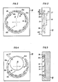
- Es zeigen: Fig. 1 ein Gesamtschema der erfindungsgemässen Vorrichtung, bei der sowohl über die Kopf- als auch über die Schieberplatte des Schiebers Gas tangential zugeführt werden kann; Fig. 2 eine Vorderansicht des mit tangentiale Ausströmrichtung aufweisenden Düsen versehenen Bereiches der Schieberplatte, der bei Verschlussstellung mit der im Schmelze-Behälter befindlichen Metallschmelze in Berührung steht; Fig. 3 eine Seitenansicht dieses Bereiches der Schieberplatte; Fig. 4 eine schematische Vorderansicht des mittangentiale Ausströmrichtung aufweisenden Düsen und einem porösen Stopfen für die Zuführung von Gasen versehenen Bereiches der Schieberplatte und Fig. 5 einen Schnitt durch eine mit einer Ausnehmung versehene Schieberplatte, wobei die Gase aus der Begrenzungswand dieser Ausnehmung tangential zugeführt werden.
- 1 shows an overall diagram of the device according to the invention, in which gas can be supplied tangentially both via the head plate and via the slide plate of the slide; 2 shows a front view of the region of the slide plate provided with tangential outflow nozzles, which in the closed position is in contact with the metal melt in the melt container; 3 shows a side view of this area of the slide plate; Fig. 4 is a schematic front view of the mid-tangential outflow having nozzles and a porous plug for the supply of gases provided area of the slide plate and FIG. 5 a section through a slide plate provided with a recess, the gases being supplied tangentially from the boundary wall of this recess.
Der in Fig. 1 nur teilweise gezeigte Behälter 1 für die zu vergiessende Metallschmelze 1 a weist in seinem unteren Bereich einen diesen Behälter 1 mit der horizontalen, ebenfalls nur teilweise gezeigten Stranggiesskokille 4 verbindenden, im wesentlichen horizontal verlaufenden Ausflusskanal 2 auf. In dem Kanal ist ein von aussen, z.B. mittels Druckzylinder betätigbarer Platten-Schieber 3 angeordnet, von dem die Kopfplatte 10 und die geteilte Schieberplatte 20 vergrössert dargestellt sind. Die feststehende, aus hochfeuerfestem Material bestehende Kopfplatte 10 ist dem Schmelze-Behälter zugewandt angeordnet und weist eine Durchfluss-Öffnung 11 auf, deren Wand 12 von den tangentiale Ausströmrichtung aufweisenden Gaszufuhrdüsen 13 durchdrungen wird. Im unteren Bereich 11 b der Öffnung 11 wurden verhältnismässig mehr Düsen 13 angeordnet als in dem oberen Bereich 11 a. Das aus diesen Düsen 13 austretende Gas verdrängt die Schmelze kontinuierlich aus dem Bereich der Schieberplatte 20.The container 1 shown only partially in FIG. 1 for the
An der Kopfplatte 10 angepresst ist die verschiebbare, ebenfalls aus feuerfestem Material gefertigte, in der gezeigten Ausführung geteilt ausgebildete Schieberplatte 20 angeordnet, deren einer Teil eine Durchflussöffnung 20a aufweist, die bei Öffnung-Stellung des Schiebers 3 mit dem Verbindungskanal 2 bzw. der Ausflussdüse und mit der Bohrung 11 der Kopfplatte 10 fluchtet. In jenem Bereich des zweiten Schieberplatten-Teiles, der bei Schliess-Stellung der Schieberplatte mit der sich im Behälter 1 befindlichen Metall-Schmelze 1 a in Berührung steht, sind in dessen Peripherie- bzw. Randzonen-Bereich die tangential mündenden Düsen 23 angeordnet, die über einen Ringkanal 28 mit dem unter Druck stehenden Spül- oder Oxidations-Gas versorgt werden. Das tangential ausströmende Gas hält die Schmelze im Bereich der Schieberplatte 10 in Bewegung und verdrängt es kontinuierlich aus deren Bereich.Pressed onto the
Aus der in Fig. 2 gezeigten Vorderansicht eines Teiles der Schieberplatte 20 ist der von einer unterbrochen dargestellten Kreislinie 22b umgrenzte Bereich 22 ersichtlich, der bei Schliess-Stellung der Schieberplatte 20 bzw. von deren entsprechendem Teil mit der Metallschmelze 1 a in Berührung steht.The front view shown in FIG. 2 of a part of the
In der Randzone 22a dieses Bereiches 22 sind die Ausströmöffnungen der Düse 23 zur tangentialen Zuführung der Gase angeordnet. Bei der in den Fig. 1 und 2 dargestellten Anordnung sind im unteren Bereich 22c mehr Tangential-Düsen angeordnet als im oberen Bereich 22d. Dadurch wird ein besonders guter Ausgleich für die über dem Querschnitt des horizontalen Ausflusskanals 2 (Fig. 1) auftretenden Unterschiede im ferrostatischen Druck und damit eine gleichmässige Bespülung des sensiblen Bereiches des Schiebers erreicht.The outflow openings of the
Aus dem in Fig. 3 gezeigten Schnitt durch den in Fig. 2 in Vorderansicht dargestellten Bereich 22 der Schieberplatte 20 sind die die Oberfläche 21 in der Randzone 22a des Flächenbereiches 22 in spitzem Winkel durchdringenden Düsen-Kanäle 23 ersichtlich, die über den Ringkanal 28 mit Gas gespeist werden.From the section shown in FIG. 3 through the
Zusätzlich zu den «tangentialen» Düsen kann vom Zentrum des Bereiches 22 nach oben versetzt und von den Düsenöffnungen 23 umgeben ein in einer Ausnehmung der Schieberplatte 20 sitzender, poröser Stopfen 25 (strichpunktiert dargestellt) vorgesehen sein, von dem aus, gespeist von der ebenfalls durch unterbrochene Linien angedeuteten Zuführungsleitung 27, die Gase flächig und sehr fein verteilt in die Metallschmelze 1 eingebracht werden.In addition to the “tangential” nozzles, a porous stopper 25 (shown in dash-dot lines) seated in a recess of the
Bei der in Fig. 4 in Vorderansicht gezeigten Ausführüngsform ist der poröse Stopfen 25 ebenfalls im oberen Teilbereich 22d des Schiebers 20 angeordnet, allerdings sind dort in diesem oberen Teil überhaupt keine Gaszufuhrdüsen mit im wesentlichen tangentialer Ausströmrichtung angeordnet; deren Aufgabe übernimmt der poröse, beispielsweise aus Zirkonoxid gefertigte Stopfen 25.In the embodiment shown in FIG. 4 in front view, the
Im unteren Bereich 22c sind hingegen die erfindungswesentlichen, tangentiale Ausströmrichtung aufweisenden Gaszufuhrdüsen 23 angeordnet, so dass auch bei dieser Ausführungsvariante eine gleichmässige Spülung des Gesamtquerschnittes trotz vertikaler Anordnung der Schieberplatte gewährleistet ist.In contrast, the
In Fig. 5 ist der in Schliess-Stellung mit der Schmelze 1 a in Berührung stehende Bereich 22 der Schieberplatte 20 einer anderen, bevorzugten Ausführungsform der erfindungsgemässen Vorrichtung im Schnitt gezeigt.5 shows the
Das gasförmige Medium wird über den Ringkanal 28 und die die zylindrische Begrenzungswand 24a der Ausnehmung 24 in der Schieberplatte 20 tangential durchdringenden Düsen 23 zugeführt.The gaseous medium is supplied via the
Die Begrenzungswand 24a der Ausnehmung 24 befindet sich im Bereich der Randzone 22a des mit der Metallschmelze 1 bei Schliess-Stellung der Schieberplatte 20 in Berührung stehenden Bereiches 22, so dass auch bei dieser Ausführungsform der erfindungsgemäss angestrebte Effekt der Spülung der sensiblen Zonen des Schiebers mit Gas erreicht wird.The
Es sei nur kurz darauf verwiesen, dass in der Öffnung 11 bzw. in deren Wand 12 der Kopfplatte 10 (siehe Fig. 1) die Anordnung der Düsen 13 in zur Anordnung der Düsen 23 in der in Fig. 5 gezeigten Wand 24a der Ausnehmung 24 der Schieberplatte 20 ganz analoger Weise vorgesehen sein kann.It should be pointed out only briefly that in the
Claims (10)
Applications Claiming Priority (2)
| Application Number | Priority Date | Filing Date | Title |
|---|---|---|---|
| AT5112/81 | 1981-11-27 | ||
| AT511281A ATA511281A (en) | 1981-11-27 | 1981-11-27 | DEVICE FOR CONTINUOUS METAL CASTING |
Publications (2)
| Publication Number | Publication Date |
|---|---|
| EP0080997A1 EP0080997A1 (en) | 1983-06-08 |
| EP0080997B1 true EP0080997B1 (en) | 1985-11-27 |
Family
ID=3572069
Family Applications (1)
| Application Number | Title | Priority Date | Filing Date |
|---|---|---|---|
| EP82890174A Expired EP0080997B1 (en) | 1981-11-27 | 1982-11-23 | Device for the continuous casting of metals |
Country Status (4)
| Country | Link |
|---|---|
| EP (1) | EP0080997B1 (en) |
| JP (1) | JPS5893543A (en) |
| AT (1) | ATA511281A (en) |
| DE (1) | DE3267714D1 (en) |
Families Citing this family (4)
| Publication number | Priority date | Publication date | Assignee | Title |
|---|---|---|---|---|
| AT383529B (en) * | 1985-10-24 | 1987-07-10 | Voest Alpine Ag | Arrangement for pouring melts |
| AU652916B2 (en) * | 1989-06-01 | 1994-09-15 | Shinagawa Refractories Co., Ltd. | Gas blowing plate brick/insert nozzle brick for sliding gate shut off |
| US5613545A (en) * | 1991-11-12 | 1997-03-25 | Shinagawa Refractories Co. Ltd. | Inert gas injecting plate brick or insert nozzle brick for use in a sliding gate valve apparatus of molten metal |
| CN118385557B (en) * | 2024-06-05 | 2025-05-02 | 靖江市科尼机械配件有限公司 | Leak protection formula slope casting device |
Citations (3)
| Publication number | Priority date | Publication date | Assignee | Title |
|---|---|---|---|---|
| DE6918019U (en) | 1968-05-09 | 1970-05-06 | Asieries Reunies De Burbach Ei | DEVICE FOR CASTING METALS, IN PARTICULAR STEEL, IN CHILLES |
| DE2462292A1 (en) | 1973-03-01 | 1977-02-17 | Uss Eng & Consult | Liquid flow control mechanism - by opening and closing a tube |
| DE2811546A1 (en) | 1977-03-18 | 1978-09-21 | Sumitomo Metal Ind | METHOD AND DEVICE FOR CONTINUOUS STEEL CASTING |
Family Cites Families (4)
| Publication number | Priority date | Publication date | Assignee | Title |
|---|---|---|---|---|
| GB801819A (en) * | 1956-03-22 | 1958-09-24 | Bram Joel Franklin | Improvements in the continuous forming of molten materials |
| CH478613A (en) * | 1968-07-12 | 1969-09-30 | Interstop Ag | Sliding closure for containers provided with a bottom pouring opening for pouring liquid metals, in particular steel |
| US3809146A (en) * | 1972-02-18 | 1974-05-07 | Steel Corp | Method of opening an intermediate vessel nozzle for continuous casting |
| DE2836409C2 (en) * | 1978-08-19 | 1982-07-22 | Stopinc AG, Zug | Device for introducing treatment substances into the melt contained in a metallurgical vessel |
-
1981
- 1981-11-27 AT AT511281A patent/ATA511281A/en not_active Application Discontinuation
-
1982
- 1982-11-19 JP JP20218082A patent/JPS5893543A/en active Pending
- 1982-11-23 DE DE8282890174T patent/DE3267714D1/en not_active Expired
- 1982-11-23 EP EP82890174A patent/EP0080997B1/en not_active Expired
Patent Citations (3)
| Publication number | Priority date | Publication date | Assignee | Title |
|---|---|---|---|---|
| DE6918019U (en) | 1968-05-09 | 1970-05-06 | Asieries Reunies De Burbach Ei | DEVICE FOR CASTING METALS, IN PARTICULAR STEEL, IN CHILLES |
| DE2462292A1 (en) | 1973-03-01 | 1977-02-17 | Uss Eng & Consult | Liquid flow control mechanism - by opening and closing a tube |
| DE2811546A1 (en) | 1977-03-18 | 1978-09-21 | Sumitomo Metal Ind | METHOD AND DEVICE FOR CONTINUOUS STEEL CASTING |
Also Published As
| Publication number | Publication date |
|---|---|
| EP0080997A1 (en) | 1983-06-08 |
| ATA511281A (en) | 1987-03-15 |
| DE3267714D1 (en) | 1986-01-09 |
| JPS5893543A (en) | 1983-06-03 |
Similar Documents
| Publication | Publication Date | Title |
|---|---|---|
| DE4023484C2 (en) | ||
| DE2709727C3 (en) | Device for replacing pouring pipes on pouring vessels during continuous casting | |
| DE2455181A1 (en) | PROCESS AND DEVICE FOR POURING METALS FROM POURS, WHOSE FLOOR OUTLET OPENING IS ADJUSTABLE BY A SLIDER | |
| DE1951447C3 (en) | Outflow slide closure for vessels for pouring metals | |
| DE2557726A1 (en) | DEVICE FOR REPLACING CURRENT PIPES, IN PARTICULAR FOR A SPOUT, LOCKABLE WITH A SLIDER LOCK, ON A TANK OF CONTINUOUS CASTING PLANTS | |
| DE3924001C2 (en) | Double roll continuous casting machine | |
| DE2355015A1 (en) | CASTING DEVICE WITH HORIZONTAL SLIDING CLOTH | |
| DE1483667A1 (en) | Method and device for the continuous casting of steel | |
| EP0080997B1 (en) | Device for the continuous casting of metals | |
| DE4138655C2 (en) | Outflow regulator for tundish | |
| DE3331483C2 (en) | Device for refractory plates of slide gate valves | |
| DE2923493A1 (en) | METHOD AND DEVICE FOR DEGASSING MOLTEN METAL | |
| DE1471914B2 (en) | DEVICE FOR THE PRODUCTION OF TABLE GLASS | |
| DE2738587C2 (en) | Adjustment device for a shielding device to protect the pouring stream | |
| DE69612992T2 (en) | METHOD AND DEVICE FOR CASTING A METAL STRIP | |
| DE2261296C3 (en) | Casting containers for metal | |
| DE3342071C2 (en) | Device for shielding a metallic pouring stream | |
| DE1213965B (en) | Device for the continuous casting of strips made of metal or other fusible materials | |
| DE2607379B2 (en) | DEVICE FOR FLUSHING STEEL | |
| DE4032787A1 (en) | DEVICE FOR CONNECTING A PIPE TO THE SPOUT OF A METAL MELTING CONTAINER | |
| DE2613363A1 (en) | CONTINUOUS CASTING MACHINE | |
| DE102008005727B3 (en) | Feeding device for a molten metal and a belt casting device equipped with such a device | |
| DE2462292A1 (en) | Liquid flow control mechanism - by opening and closing a tube | |
| DE1295757B (en) | Device for the removal of liquid metal and slag from the axially arranged discharge opening of a rotary kiln | |
| WO2023174796A1 (en) | Dispensing device for intermittently dispensing a cooling medium onto a cast strand |
Legal Events
| Date | Code | Title | Description |
|---|---|---|---|
| PUAI | Public reference made under article 153(3) epc to a published international application that has entered the european phase |
Free format text: ORIGINAL CODE: 0009012 |
|
| AK | Designated contracting states |
Designated state(s): BE CH DE FR GB IT LI SE |
|
| 17P | Request for examination filed |
Effective date: 19830712 |
|
| RAP1 | Party data changed (applicant data changed or rights of an application transferred) |
Owner name: ZIMMERMANN & JANSEN GMBH Owner name: HAISSIG, MANFRED, DIPL.-ING. |
|
| ITF | It: translation for a ep patent filed | ||
| GRAA | (expected) grant |
Free format text: ORIGINAL CODE: 0009210 |
|
| AK | Designated contracting states |
Designated state(s): BE CH DE FR GB IT LI SE |
|
| REF | Corresponds to: |
Ref document number: 3267714 Country of ref document: DE Date of ref document: 19860109 |
|
| ET | Fr: translation filed | ||
| PLBI | Opposition filed |
Free format text: ORIGINAL CODE: 0009260 |
|
| 26 | Opposition filed |
Opponent name: DIDIER-WERKE AG Effective date: 19860825 |
|
| PG25 | Lapsed in a contracting state [announced via postgrant information from national office to epo] |
Ref country code: DE Effective date: 19871113 |
|
| PG25 | Lapsed in a contracting state [announced via postgrant information from national office to epo] |
Ref country code: SE Effective date: 19871124 |
|
| RDAG | Patent revoked |
Free format text: ORIGINAL CODE: 0009271 |
|
| STAA | Information on the status of an ep patent application or granted ep patent |
Free format text: STATUS: PATENT REVOKED |
|
| BERE | Be: lapsed |
Owner name: ZIMMERMANN & JANSEN G.M.B.H. Effective date: 19871130 Owner name: HAISSIG MANFRED Effective date: 19871130 |
|
| GBPR | Gb: patent revoked under art. 102 of the ep convention designating the uk as contracting state | ||
| 27W | Patent revoked |
Effective date: 19880124 |
|
| REG | Reference to a national code |
Ref country code: CH Ref legal event code: PL |
|
| EUG | Se: european patent has lapsed |
Ref document number: 82890174.4 Effective date: 19880913 |