EP0080679A2 - Vorrichtung zum Entfernen und/oder Einsetzen von Brennstoffelementen eines Kernreaktors - Google Patents
Vorrichtung zum Entfernen und/oder Einsetzen von Brennstoffelementen eines Kernreaktors Download PDFInfo
- Publication number
- EP0080679A2 EP0080679A2 EP82110771A EP82110771A EP0080679A2 EP 0080679 A2 EP0080679 A2 EP 0080679A2 EP 82110771 A EP82110771 A EP 82110771A EP 82110771 A EP82110771 A EP 82110771A EP 0080679 A2 EP0080679 A2 EP 0080679A2
- Authority
- EP
- European Patent Office
- Prior art keywords
- line
- setpoint
- crane
- load
- drive
- Prior art date
- Legal status (The legal status is an assumption and is not a legal conclusion. Google has not performed a legal analysis and makes no representation as to the accuracy of the status listed.)
- Granted
Links
Images


Classifications
-
- G—PHYSICS
- G21—NUCLEAR PHYSICS; NUCLEAR ENGINEERING
- G21C—NUCLEAR REACTORS
- G21C19/00—Arrangements for treating, for handling, or for facilitating the handling of, fuel or other materials which are used within the reactor, e.g. within its pressure vessel
- G21C19/20—Arrangements for introducing objects into the pressure vessel; Arrangements for handling objects within the pressure vessel; Arrangements for removing objects from the pressure vessel
-
- B—PERFORMING OPERATIONS; TRANSPORTING
- B66—HOISTING; LIFTING; HAULING
- B66C—CRANES; LOAD-ENGAGING ELEMENTS OR DEVICES FOR CRANES, CAPSTANS, WINCHES, OR TACKLES
- B66C15/00—Safety gear
- B66C15/06—Arrangements or use of warning devices
- B66C15/065—Arrangements or use of warning devices electrical
-
- B—PERFORMING OPERATIONS; TRANSPORTING
- B66—HOISTING; LIFTING; HAULING
- B66C—CRANES; LOAD-ENGAGING ELEMENTS OR DEVICES FOR CRANES, CAPSTANS, WINCHES, OR TACKLES
- B66C13/00—Other constructional features or details
- B66C13/04—Auxiliary devices for controlling movements of suspended loads, or preventing cable slack
- B66C13/10—Auxiliary devices for controlling movements of suspended loads, or preventing cable slack for preventing cable slack
- B66C13/105—Auxiliary devices for controlling movements of suspended loads, or preventing cable slack for preventing cable slack electrical
-
- B—PERFORMING OPERATIONS; TRANSPORTING
- B66—HOISTING; LIFTING; HAULING
- B66D—CAPSTANS; WINCHES; TACKLES, e.g. PULLEY BLOCKS; HOISTS
- B66D1/00—Rope, cable, or chain winding mechanisms; Capstans
- B66D1/54—Safety gear
- B66D1/58—Safety gear responsive to excess of load
-
- Y—GENERAL TAGGING OF NEW TECHNOLOGICAL DEVELOPMENTS; GENERAL TAGGING OF CROSS-SECTIONAL TECHNOLOGIES SPANNING OVER SEVERAL SECTIONS OF THE IPC; TECHNICAL SUBJECTS COVERED BY FORMER USPC CROSS-REFERENCE ART COLLECTIONS [XRACs] AND DIGESTS
- Y02—TECHNOLOGIES OR APPLICATIONS FOR MITIGATION OR ADAPTATION AGAINST CLIMATE CHANGE
- Y02E—REDUCTION OF GREENHOUSE GAS [GHG] EMISSIONS, RELATED TO ENERGY GENERATION, TRANSMISSION OR DISTRIBUTION
- Y02E30/00—Energy generation of nuclear origin
- Y02E30/30—Nuclear fission reactors
-
- Y—GENERAL TAGGING OF NEW TECHNOLOGICAL DEVELOPMENTS; GENERAL TAGGING OF CROSS-SECTIONAL TECHNOLOGIES SPANNING OVER SEVERAL SECTIONS OF THE IPC; TECHNICAL SUBJECTS COVERED BY FORMER USPC CROSS-REFERENCE ART COLLECTIONS [XRACs] AND DIGESTS
- Y10—TECHNICAL SUBJECTS COVERED BY FORMER USPC
- Y10S—TECHNICAL SUBJECTS COVERED BY FORMER USPC CROSS-REFERENCE ART COLLECTIONS [XRACs] AND DIGESTS
- Y10S294/00—Handling: hand and hoist-line implements
- Y10S294/906—Atomic fuel handler
Definitions
- This invention relates to the art of nuclear reactor power plants and has particular relationship to the transfer of fuel assemblies to and from nuclear reactors during fueling, refueling and the like. While this invention is uniquely applicable to nuclear reactors, it ie realized that the invention may have applicability in other arts. To the extent this invention is applied in other arts, such application is regarded as within the scope of equivalents of this invention. It is also understood that while this invention is predominantly practiced to transfer fuel assemblies, it may also be applied to the transfer of individual fuel rods. Such application is within the scope of equivalents of this invention.
- the core of a nuclear reactor with its fuel assemblies is immersed in highly radioactive water in the pressure vessel.
- the spent fuel assemblies which are to be removed are also highly radioactive. These fuel assemblies are positioned in slots in the core.
- the spent fuel assemblies are removed to a vehicle which carries them to a pit where they are stored under water as nuclear waste.
- the replacement fuel assemblies are removed from a vehicle and transferred to the reactor where they are inserted in the slots vacated by the spent fuel assemblies.
- the transfer of fuel assemblies between the vehicles and the reactor and the insertion of replacement fuel assemblies in the slots in the core is accomplished by a crane.
- the crane carries a line which terminates in a fixture for engaging the fuel assemblies.
- the fixture has fingers which are expansible and collapsible under hydraulic pressure.
- Each fuel assembly has a hole in its top.
- the crane has a traverse drive which positions the fixture with the fingers collapsed over a fuel assembly.
- the line drive guides the fixture into the hole in the assembly.
- the fingers are expanded to grip the fuel assembly.
- the line drive is energized to raise and remove the fuel assembly.
- Other facilities for engaging the fuel assemblies are also feasible.
- each assembly may be provided in its top with an eyelet to be engaged by a hook terminating the crane line.
- the invention resides in apparatus for removing and/or positioning fuel assemblies of a nuclear reactor during fueling, refueling or the like, said apparatus including a crane, said crane having a line terminating in a fixture to be engaged with a fuel assembly to be removed and to be disengaged from a positioned fuel assembly, a line drive, connected to said line, to drive said line, characterized in that the apparatus includes load-sensing means, connected to said line, for sensing a load on said line, setpoint means for setting a high-level load setpoint and a low-level load setpoint, said high-level setpoint setting an upper limit on the loading of said crane when said line is exerting an upward force, said low-level setpoint setting an upper limit on the loading of said crane when a downward force is exerted on said line, for example by a fuel assembly being lowered, means, connected to said line drive and responsive to said load-sensing means, for disabling said line drive if the load on said crane exceeds said high-level setpoint, and means
- apparatus including a crane and a hoist load monitor responsive to the loads on the crane throughout its operations in the transfer of a fuel assembly.
- a control interfaced between the monitor and the crane responsive to the monitor for controlling the crane.
- the apparatus includes a load sensor, typically a strain gauge, which supplies intelligence to the load sensor as to the loading of the crane.
- the intelligence provided by the load sensor includes a measure of the loading when a fuel assembly is being raised, a measure of the loading when the assembly is being lowered and a measure indicating that the crane line is slack; i.e, carries loading less than the weight of the line and fixture alone.
- the monitor includes setpoint means for setting desired levels of loading.
- the setpoints include a high-level (HL) setpoint, a low-level (LL) setpoint, and a slack-line (SL) setpoint.
- HL high-level
- LL low-level
- SL slack-line
- Appropriate indicators and signals for indicating the status of the loading with respect to the setpoints are provided.
- the HL setpoint is predominantly significant during raising of a fuel assembly. When the load sensor indicates that this setpoint is exceeded, the crane line drive is deenergized.
- the LL setpoint is predominantly significant during lowering of a fuel assembly. Measure by the load sensor of loading less than the LL setpoint indicates that the fuel assembly being lowered has contacted an obstruction, either by engagement with boundaries of a fuel assembly slot or because the fuel assembly has been seated in the slot.
- the operator can determine which of these events has occurred from the length of line taken up in the lowering and also by observation of the water in the reactor.
- the LL setpoint serves another purpose. Once the LL setpoint is exceeded during lowering, the traverse drive is deenergized and is locked in the deenergized condition so that there can be no traverse even if the loading decreases to a magnitude between the LL setpoint and the SL setpoint. To unlock the traverse drive, it is necessary that the measure of the load sensor be less than the SL setpoint, i.e. less than the loading of line and fixture alone. This indicates that the crane line is slack. With the crane line slack, the fixture is disconnected from a fuel assembly.
- the crane line is subsequently raised to a position where the SL setpoint is exceeded. If the disconnection is effective, the loading is less than the LL setpoint and the crane line can be traversed laterally. If the disconnection is not effective, the LL setpoint is exceeded and the traverse drive is locked precluding traverse by the crane line and the fuel assembly which it carries.
- the setpoints may be changed. However the mechanisms for changing the setpoints are in a locked cabinet for which only the supervisors have the key.
- the HL setpoint may be overridden. This purpose is accomplished by a key switch. Only the supervisors have the key. The key cannot be removed from the key slot unless it is turned to the non-overriding setting.
- the setpoints are digital and their indications are digital.
- the measures of the load sensor are connected to digital magnitudes.
- the digital magnitudes avail a measure of the loading in pounds or kilograms.
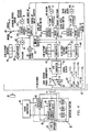
- the apparatus shown in the drawings includes a crane 11, a crane control pendant 13, a hoist-load monitor 15 and an interface control 17 interfaced between the monitor 15 and the controller 13.
- the hoist-load monitor 15 and the interface control 17 are shown as separate units in separate containers. In the customary practice of this invention, these components actually are separate units in separate boxes. However, these components may be integrated with the crane 11 or may be combined physically. The significance to this invention of these' components resides in their electrical cooperation with the crane and not in their physical structures.
- the crane 11 (Figs. 2 and 3) is of conventional construction. It includes parallel rails 19 and 21 along which a cross rail . 23 is movable. Along the cross rail a carriage 25 is movable. A crane line 27 is suspended from the carriage 25. The line terminates in a fixture 29, typically including expansible and collapsible fingers 31.
- the crane line 27 includes a chain or cable loop 33 which may be wound or unwound from pulley wheels 35 and 36 to raise or lower the fixture 29.
- a load sensor 37 In one branch of the cable 3, there is a load sensor 37.
- the load sensor 37 is of the full-bridge, strain gauge type (Fig. 5). As shown in Fig.
- the line 27 extends into the water 39 of a reactor 41 with its fingers 31 engaging a fuel assembly 43 disposed in a slot bounded by walls 45, which may be the walls of adjacent fuel assemblies.
- the carriage contains the line drive 47, the traverse drive 49 and the crane controller 51.
- the line drive 47 drives pulley wheels 35 and 36 to raise or lower the line 27.
- the traverse drive 49 drives the cross rail 23 along rails 19 and 20 and the carriage 25 along the cross rail 23.
- the crane controller 51 controls the operation of the drives 47 and 49 and of other components of the crane 11 such as indicators in the carriage 25.
- the carriage includes hydraulic means (not shown) which supplies fluid to open or close the fingers 31 of the fixture 29.
- the carriage 25 also contains a limit switch 53 which is in the energizing circuit of traverse drive 49.
- This switch is closed by the build-up of cable on pulley wheel 36 when the loop 33 is wound up and the crane line 27 is in the uppermost position. Once the line departs from the uppermost position, limit switch 53 is opened and the energizing circuit for traverse drive 49 through the switch is open.
- the pendant includes push-buttons (not shown) for operating the crane 11.
- push-buttons for operating the crane 11.
- a "START” button which starts operation of the crane
- a "STOP” button which stops operation
- a "RAISE” button which enables or energizes the line drive 47 to raise the line 27
- a "LOWER” button to enable the line drive to lower.the line
- a plurality of buttons to control the enabling and direction of the traverse drive 49.
- the traverse drive 49 may include two motors, one to move the carriage -25 and the other to move the cross beam. Each of the latter motors is controlled by two pushbuttons on the pendant 13.
- the interface control 17 includes the load-sensor power supply 61, the low-level DC power supply 63 for the monitor 15, relays SSR1, SSR2, SSR3, and a bypass circuit 65 for enabling the crane to operate without the monitor 15 typically, in the event that monitor 15 becomes defective.
- the crane can be operated in its normal manual mode. This is accomplished by disconnecting monitor 15 and inserting shorting connector JX (Fig. 4) into cable connector Pl.
- the by-pass circuit 65 is then actuated and the crane can be operated manually.
- Three cables terminate in the interface control. One cable is the load-sensor cable. Another cable provides the interface connections to the crane controller 51. This cable includes eight conductors.
- the monitor 15 is of the low-level DC type.
- the relays SSR1, SSR2, SSR3 are of the solid-state optical type. Each relay includes a light emitting diode or transistor (not shown) which is dark or emits light depending on the signal to it from the sensor 15. In each relay a light sensitive transistor or silicon-controlled rectifier (not shown) responsive to the light-emitting diode, performs the relaying function.
- the relays SSR1, SSR2, SSR3 are of the optical type to isolate the low-level control logic of the monitor 15 from the higher level power in the interface control 17.
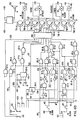
- the monitor 15 includes a load-sensor signal conditioner 71.
- This signal conditioner is shown in detail in Fig. 5. It includes the cascaded operational amplifiers Ul and U2.
- Fig. 5 shows the magnitude of the components connected to these amplifiers. The purpose of this showing is to aid those skilled in the art in practicing this invention and not with any intention or in any way restricting this invention.
- the input to Ul is derived from the output of the load sensor 37 which is assumed to be a strain bridge.
- the output of Ul is impressed between the negative and positive inputs of U2 through resistor- capacitor filter network 73. This network serves to suppress high-frequency noise in the output of Ul.
- a selectable bias is impressed on the positive terminal of U2 through the variable resistor 77 to eliminate the effects of any undesired weight on the line, for example weights on fixture 29 (Fig. 3).
- the range of the conditioned signal is set by span variable resistor 79 from which the output of U2 is derived.
- a readily accessible test point 78 is connected to the output of Ul.
- the network 81 serves to test the response of the monitor 15 to the output of the load sensor.
- This network includes pushbutton 83 (Fig. 7) in series with resistor 85, pushbutton 87 in series with potentiometer 89, pushbutton 91 in series with potentiometer 93, and pushbutton 95 in series with resistor 97.
- Each of these buttons when closed operates to connect its resistor or potentiometer across a resistor 99 of the load sensor 37.
- resistor 85 connected across resistor 93
- the load sensor 37 is set for a magnitude less than slack-line setpoint.
- potentiometer 89 connected across resistor 99
- the load sensor is set for a magnitude greater than slack-line setpoint but less than low-load setpoint.
- potentiometer 93 across resistor 99 the load sensor is set for a magnitude greater than low-load setpoint but less than high-load setpoint.
- resistor 97 across resistor 99 the load sensor is set for a magnitude greater than high-load setpoint.
- the resistors 85 and 97 are so selected and the potentiometers are so set that on the closing of a pushbutton a predetermined selected magnitude is displayed on the associated indicator 113 (Fig. 7).
- the output of the signal conditioner 71 is supplied to an analog-to-digital converter 111 which converts the analog signals from the load sensor 37 into digital signals.
- the output of the A/D 111 produces a display of the load on the crane line 27 on an indicator 113 (Fig. 7).
- the output of the A/D is also supplied to comparators 115, 117 and 119 in parallel.
- the comparators are digital.
- Each comparator includes buttons 121, 123, 125 (Fig. 7) for setting separately its digits.
- the HL setpoint is set on comparator 115, the LL setpoint on comparator 117, and the SL setpoint on comparator 119..
- the numbers at the output of A/D 111 are compared with the numbers set on comparators 115-119 and appropriate signaling and processing based on the results of the comparison is produced.
- inhibit circuit A connected to the output of comparator 115, actuates relay SSR1 to the "ON" setting and the raising of the load proceeds normally.
- the output of the high comparator 115 conducts and initiates three functions. First, the HIGH ALARM OVERLOAD indicator 131 illuminates; second, the audible alarm 133 sounds in a pulsing mode.
- the output of the inhibit circuit A turns off thus turning off SSR1 which inhibits the hoist from being raised.
- the output of SSR1 is in series with the crane line up controls of the crane 11. If the overload is removed, the HIGH ALARM 131 indicator goes out and the audible alarm 133 is silenced.
- the operator may elect to override this condition by placing the overload bypass switch 135 in the BYPASS mode. A key is required to operate the high bypass switch. This switch 135 enables bypass circuit 136 to override the blocking function which prevents operation of the crane 11 under overload. When this switch is in the BYPASS mode, the OVERLOAD BYPASSED indicator 137 is illuminated red and pulsates.
- the audible alarm and high overload indicator are also energized.
- SSR1 When in the OVERLOAD BYPASSED mode, SSR1 is again energized allowing the crane line 27 to be operated in the UP mode with an overload. Again, as described previously, when the overload is removed, the HI ALARM and audible alarm are turned off; however, the OVERLOAD BYPASSED indicator continues to pulsate to remind the operator that the key operated function is in the bypassed mode and should be returned to NORMAL. When this key operated switch is placed in NORMAL, the pulsating OVERLOAD BYPASSED indicator goes out. It is pointed out that no matter what the load or alarming condition, the digital display always displays the load in pounds or kilograms on indicator 113.
- inhibit circuit B Under normal conditions when the load is less than the low load setpoint, inhibit circuit B is in the ON condition which energizes SSR2 whose output is in series with the crane control partial up switch circuit. This circuit controls the crane traverse operation. When the hoist load exceeds the low setpoint setting, inhibit circuit A turns off, thus deenergizing SSR2 and therefore inhibiting crane traversing in the partial up mode. Once this circuit is inhibited, it remains in this mode until it is reset by the slack cable setpoint signal. This reset action takes place when the hoist load is less than the slack cable setpoint. This operating function cannot be bypassed.
- the crane line 27 can be lowered.
- SSR3 is energized and its output is in series with the hoist down controls.
- inhibit circuit C turns off thus deenergizing SSR3.
- the hoist down circuit is inhibited and the LOW ALARM indicator 141 is illuminated. If the load later exceeds the LL setpoint the LOW ALARM indicator 14 goes out and the apparatus is in the initial operating condition.
- the operator may continue hoist down operations by depressing the LOW ALARM indicator pushbutton 143.
- This indicator 141 is one of the only two units that are indicating pushbuttons. This places the LOW ALARM in the BYPASS mode and causes the illuminated LOW ALARM indicator to pulsate. The operator may now continue hoist lowering conditions.
- the operator may continue to lower the crane line 27.
- the S.C. ALARM indicator 145 illuminates, the pulsating LOW ALARM indicator goes out and the hoist lowering circuit is again inhibited from lowering.
- the operator may now depress the S.C. indicator alarm pushbutton 147 which places the S.C. inhibit circuit D in the bypass mode and causes the S.C. ALARM indicator to pulsate.
- the crane line can Be lowered again.
- Switches 145 and 147 are indicating pushbuttons.
- inhibit circuit D With the loading on the crane line 27 less than the SL setpoint, inhibit circuit D is enabled to reset inhibit circuit B so that the traverse drive 49 is enabled.
- inhibit circuit D When the loading now becomes greater than the SL setpoint but less than the LL setpoint, inhibit circuit D is reset but inhibit circuit B remains in the ON condition.
- Relay SSR2 remains ON and the traverse drive 49 remains enabled.
- the SL ALARM 145 goes out and the LL ALARM 141 is illuminated. If the loading exceeds LL setpoint inhibit circuit B and relay SSR2 ⁇ are set in OFF and LOW ALARM 141 is turned off. Traverse drive 49 is disabled.
- the comparator -115 includes units Ull, U12 and U13.
- Unit Ull compares the least significant digits of the HL setpoint with the least significant digits of the signal from the load sensor 111.
- Unit U12 compares the digits of intermediate significance of the HL setpoint and of the signal from the load sensor 37.
- U13 compares the most significant digit of the HL setpoint and the signal from the load sensors. The corresponding digits are presented in Fig. 7 as 2,2,0. The evaluation of the loading is to ⁇ 10 pounds and for this reason the fourth digit is not set.
- the LL setpoint and the corresponding signal from the load sensor are compared in units U14, U15, U16 and the SL setpoint and the corresponding signal from the load sensor in units U17, U18, U19.
- the A/D 111 includes a digital meter (113) whose digital output corresponds to the response of the load sensor 37.
- the signals derived from the A/D 111 are entered as 1's or 0's on the upper four inputs of each unit Ull through U18, through sets of conductors 151, 153, 155.
- the setpoints are set on the lower four inputs of each unit Ull through U18, through sets of conductors 157 through 173.
- Conductors 175H, 177H and 179H transmit intelligence as to the result of the comparison from unit Ull to unit U12.
- a 1 entered on conductor 175H and 0's on 177H and 179H signals that the most significant digit of the HL setpoint is exceeded by the most significant digit of the load-sensor signal;
- a 1 entered on conductor 177H and 0's in 175H and 179H signals that the most significant digit of the HL setpoint exceeds the most significant digit of the load sensor signal;
- a 1 entered on conductor 179H and 0's on 175H and 177H signals that the most significant digits of the HL setpoint and load sensor signals are equal.
- Conductors 181H, 183H and 185H perform the same function in the comparison of the digits of intermediate significance of the HL setpoint and of the load sensor signal. Corresponding functions are performed by conductors 175L through 185L of the low level comparator 117 and by the conductors 175S through 185S of the slack line comparator 119.
- the output conductors 187, 189, 191 of the most significant digit units U13, U16 and U19 are each connected to a flip-flop U10-A, U9-B and U9-A, respectively.
- a 1 on conductor 187 signals that the HL setpoint is exceeded, a 1 on conductor 189 that the LL setpoint is exceeded, and a 1 on conductor 181 that the SL setpoint is exceeded.
- the flip-flops U10-A, U9-B and U9-A are conditioned to respond by the leading edge a 1 on data-ready conductor 193 which is connected to the conditioning inputs of the flip-flops.
- the data-line ready conductor 193 receives its intelligence from A/D 111.
- a 0 on input conductor 187 of flip-flop U10-A produces a 0 on its upper output conductor 195 and a 1 on its lower output conductor 197.
- a 1 on 187 produces a 1 on conductor 195 and 0 on 197.
- a 0 on input conductor 189 of flip-flop U9-B produces a 0 on its output conductor 199 and a 1 on 189 produces a 1 on 199.
- a 0 on input conductor 191 of of flip-flop U9-A produces a 0 on its output 201 and a 1 on 191 produces a 1 on 201.
- the load on line 27 is greater than LL setpoint and less than HL setpoint.
- TN1-A is non-conducting and sound alarm 133 is disabled.
- TN1-B is non-conducting and HI OVERLOAD light 131 is extinguished.
- Switch 135 is not closed but there is a 1 on the base of transistor TN1-C from line 195 through NAND U7-B, or U8-A, bank RN-1.
- TN1-C is energized.
- This transistor is connected to actuate relay SSR1 to ON when energized.
- the line drive 47 is enabled to raise the load 43. Since the bypass switch 135 is open, there is a 0 on conductor 205.
- the flow of square-wave pulses from oscillator U20-A to the base of transistor TN1-D through NAND U7-D, NAND U7-C and bank RN1 is blocked by NAND U7-D and bypass light 137 is dark. There is a 1 on conductor 201.
- the signal sensed by the load sensor 37 is less than LL setpoint but greater than SL setpoint.
- the only change from normal is a 0 on conductor 199.
- the load-sensor 37 senses only the weight of the line and fixture 29 and the load-sensor signal is greater than SL setpoint and less than LL setpoint.
- the SL ALARM 145 is dark.
- the traverse drive 49 is enabled and the line 27 terminating only in fixture 29 may be traversed to another load.
- Thre is also a 1 on the base of transistor TH1-C from conductor 195 through NAND U7-B enabling the raise function of the line drive 47.
- a 1 on 201 there is a 1 on the lower input of AND U5-D.
- AND U5-D there is also a 1 on the upper input of AND U5-D because there are 1's on inputs 211 and 213 of flip-flop 207 and 1 on its output 208 and on the lower input of OR U4-C.
- TH2-B is conducting and the lower function of the line drive is enabled.
- Apparatus according to this invention has a number of advantages.
- the control panel and the electronics may be small and occupy a minimum of space. Since all circuits except for the signal conditioner 71 are digital, trouble-shooting of the apparatus is facilitated.
- the apparatus lends itself to the inclusion of a self-testing and calibrating circuit in such a way as to assure that all interlock and safety circuits function properly prior to loading of a crane 11.
- the feature may be entirely self-contained and requires no signal input from an external source. No AC power is used within the hoist-load monitor 15.
- the apparatus has a wide range and is capable of monitoring loads up to 19999 pounds.
- the apparatus can be scaled to function with any strain-gauge bridge-type transducer 37. It could use the setpoints to evaluate other parameters than tension such as pressure, torque or force.
Landscapes
- Engineering & Computer Science (AREA)
- Mechanical Engineering (AREA)
- Physics & Mathematics (AREA)
- Plasma & Fusion (AREA)
- General Engineering & Computer Science (AREA)
- High Energy & Nuclear Physics (AREA)
- Control And Safety Of Cranes (AREA)
- Chain Conveyers (AREA)
Applications Claiming Priority (2)
| Application Number | Priority Date | Filing Date | Title |
|---|---|---|---|
| US325881 | 1981-11-30 | ||
| US06/325,881 US4487741A (en) | 1981-11-30 | 1981-11-30 | Transfer of fuel assemblies |
Publications (3)
| Publication Number | Publication Date |
|---|---|
| EP0080679A2 true EP0080679A2 (de) | 1983-06-08 |
| EP0080679A3 EP0080679A3 (en) | 1985-08-28 |
| EP0080679B1 EP0080679B1 (de) | 1987-08-19 |
Family
ID=23269865
Family Applications (1)
| Application Number | Title | Priority Date | Filing Date |
|---|---|---|---|
| EP82110771A Expired EP0080679B1 (de) | 1981-11-30 | 1982-11-22 | Vorrichtung zum Entfernen und/oder Einsetzen von Brennstoffelementen eines Kernreaktors |
Country Status (10)
| Country | Link |
|---|---|
| US (1) | US4487741A (de) |
| EP (1) | EP0080679B1 (de) |
| JP (1) | JPS58103697A (de) |
| KR (1) | KR900008688B1 (de) |
| DE (1) | DE3277013D1 (de) |
| EG (1) | EG16941A (de) |
| ES (1) | ES517737A0 (de) |
| GB (1) | GB2110634B (de) |
| IL (1) | IL66978A (de) |
| IT (1) | IT1157342B (de) |
Cited By (7)
| Publication number | Priority date | Publication date | Assignee | Title |
|---|---|---|---|---|
| DE3714903A1 (de) * | 1987-05-05 | 1988-11-24 | Skt Podem | Ueberlastbegrenzer fuer hebemaschinen |
| FR2701761A1 (fr) * | 1993-02-19 | 1994-08-26 | Reichert Joseph | Procédé et dispositif pour l'analyse d'un câble en mouvement par capteurs électromagnétiques. |
| FR2708770A1 (fr) * | 1993-08-06 | 1995-02-10 | Ainf | Procédé de contrôle d'une machine mobile et dispositif pour sa mise en Óoeuvre. |
| EP0827935A1 (de) * | 1996-09-10 | 1998-03-11 | Reel S.A. | Verfahren zum Steuern des Betriebs einer Lastkompensationsvorrichtung und Lastkompensationsvorrichtung zur Durchführung dieses Verfahrens |
| WO2008151744A1 (de) | 2007-06-11 | 2008-12-18 | Sew-Eurodrive Gmbh & Co. Kg | Anordnung, modul und verfahren zum sicheren betreiben einer anlage |
| EP2123591A1 (de) * | 2008-05-20 | 2009-11-25 | NKM Noell Special Cranes | Vorrichtung zum Überlastungsschutz eines Kranes |
| FR2981340A1 (fr) * | 2011-10-13 | 2013-04-19 | Airbus | Systeme et procede de levage de charge, en particulier de moteur d'aeronef. |
Families Citing this family (28)
| Publication number | Priority date | Publication date | Assignee | Title |
|---|---|---|---|---|
| US4636962A (en) * | 1983-05-24 | 1987-01-13 | Columbus Mckinnon Corporation | Microprocessor-controlled hoist system |
| ATE34479T1 (de) * | 1983-09-06 | 1988-06-15 | Acec | Verfahren sowie einrichtung zur ueberwachung und kontrolle der be- und entladearbeiten des brennstoffs eines kernreaktors. |
| US4683109A (en) * | 1985-02-19 | 1987-07-28 | Westinghouse Electric Corp. | Debris removal system for a nuclear fuel assembly |
| US4683110A (en) * | 1985-06-14 | 1987-07-28 | Proto-Power Corporation | Apparatus and method for consolidating spent fuel rods |
| US4659536A (en) * | 1985-06-14 | 1987-04-21 | Proto-Power Corporation | System and method for consolidating spent fuel rods |
| US4715111A (en) * | 1985-06-20 | 1987-12-29 | Westinghouse Electric Corp. | Remote repair system for nuclear fuel rod assemblies |
| FR2593108A1 (fr) * | 1986-01-22 | 1987-07-24 | Transnucleaire | Dispositif de manutention multipinces avec limiteur individuel d'effort. |
| US4699750A (en) * | 1986-02-26 | 1987-10-13 | Westinghouse Electric Corp. | Apparatus for storage, retrieval and deployment of drag gages used in fuel assembly inspection |
| US4699753A (en) * | 1986-03-27 | 1987-10-13 | Westinghouse Electric Corp. | Reactor refueling machine simulator |
| JPH0664177B2 (ja) * | 1986-09-26 | 1994-08-22 | 株式会社日立製作所 | 原子炉燃料交換機の制御方式 |
| US4749541A (en) * | 1986-12-05 | 1988-06-07 | Westinghouse Electric Corp. | Position sensing mechanism for a nuclear fuel transfer system |
| DE3714728A1 (de) * | 1987-05-02 | 1988-11-10 | Schering Ag | Anordnung zum absenken, bzw. hochheben von warentraegern zwecks beschicken von baedern von chemischen anlagen |
| FR2615500B1 (fr) * | 1987-05-20 | 1989-07-28 | Reel Sa | Dispositif compensateur de charge pour un engin de manutention et procede pour la mise en oeuvre d'une telle compensation |
| US4894849A (en) * | 1988-09-30 | 1990-01-16 | Westinghouse Electric Corp. | Apparatus and method for transferring nuclear reactor fuel assemblies |
| US5377240A (en) * | 1993-10-21 | 1994-12-27 | General Electric Company | Transfer carriage with interchangeable baskets |
| CA2123065C (en) * | 1994-02-16 | 1998-09-15 | Curt J. Waedekin | Lifting apparatus including overload sensing device |
| US6404836B1 (en) * | 1999-02-12 | 2002-06-11 | Westinghouse Electric Company Llc | Removable spent fuel handling machine rail |
| DE10233875B4 (de) * | 2002-07-25 | 2008-08-14 | Siemens Ag | Krananlage, insbesondere Containerkran |
| WO2004078630A2 (en) * | 2003-03-05 | 2004-09-16 | Charles Patrick De Klerk | A method of operating a hoisting device and an accessory for a hoisting device |
| KR100586737B1 (ko) * | 2003-12-26 | 2006-06-08 | 한국전자통신연구원 | SOI 기판 위에 구현된 NMOS 소자, PMOS 소자및 SiGe BiCMOS 소자 및 그 제조 방법 |
| FR2900142B1 (fr) * | 2006-04-25 | 2008-05-23 | Reel Soc Par Actions Simplifie | Dispositif compensateur de charge, notamment pour engin de levage |
| WO2013130105A1 (en) * | 2012-03-02 | 2013-09-06 | Nuscale Power, Llc | Servicing a nuclear reactor module |
| US10854345B2 (en) | 2012-03-02 | 2020-12-01 | Nuscale Power, Llc | Servicing a nuclear reactor module |
| GB2505932A (en) * | 2012-09-15 | 2014-03-19 | Garry Richard Wright | Crane hoist rope pay-out system |
| US9284161B2 (en) * | 2014-04-29 | 2016-03-15 | National Oilwell Varco, L.P. | Self-balancing spreader beam |
| US10077168B2 (en) * | 2014-05-07 | 2018-09-18 | The Caldwell Group, Inc. | Automatic leveling device with adjustable orientation setting |
| RU2637498C1 (ru) * | 2016-08-05 | 2017-12-05 | Акционерное общество "Всероссийский научно-исследовательский и проектно-конструкторский институт атомного энергетического машиностроения" (АО "ВНИИАМ") | Устройство для извлечения упавших предметов ядерного реактора |
| RU2684392C2 (ru) * | 2016-12-28 | 2019-04-09 | Акционерное общество "Научно-производственное объединение "Центральный научно-исследовательский институт технологии машиностроения", АО "НПО "ЦНИИТМАШ" | Устройство для извлечения упавших предметов ядерного реактора |
Citations (3)
| Publication number | Priority date | Publication date | Assignee | Title |
|---|---|---|---|---|
| US3912093A (en) * | 1974-10-11 | 1975-10-14 | Peterson Tractor Co | Hoist truck with planetary gear assemblies and load sensor means |
| FR2359780A1 (fr) * | 1976-07-28 | 1978-02-24 | Lorraine Laminage | Procede et dispositif pour le controle de l'accrochage de charges soulevees par plus d'un point |
| FR2426637A1 (fr) * | 1978-05-26 | 1979-12-21 | Commissariat Energie Atomique | Appareil de levage muni d'un systeme de securite |
Family Cites Families (15)
| Publication number | Priority date | Publication date | Assignee | Title |
|---|---|---|---|---|
| GB977215A (en) * | 1962-11-03 | 1964-12-02 | Mole Richardson England Ltd | Improved lamp supporting structures for film and television studios |
| GB1042557A (en) * | 1965-05-20 | 1966-09-14 | Joseph Edward Fawell | Hoist safety device |
| CH513493A (de) * | 1970-03-25 | 1971-09-30 | Bbc Brown Boveri & Cie | Einrichtung zur Überwachung des Betriebes einer Antriebsvorrichtung eines in einem gasgekühlten Kernreaktor angeordneten als Regel- und Notabschaltstab dienenden Steuerstabes |
| US3740741A (en) * | 1971-05-26 | 1973-06-19 | Eaton Corp | Alarm set point control system |
| DE2164628C3 (de) * | 1971-12-24 | 1978-03-16 | Siegfried Dipl.-Ing. Dr.-Ing. 4930 Detmold Gross | Überlastabschalteinrichtung für hintereinandergekoppelte hydraulische Hubbzw. Verstellmechanismen |
| DE2220994A1 (de) * | 1972-04-28 | 1973-11-08 | Daimler Benz Ag | Mit seilen arbeitende hebezeuge |
| US3913081A (en) * | 1973-10-23 | 1975-10-14 | Eaton Corp | Crane load warning system |
| US4081086A (en) * | 1974-02-06 | 1978-03-28 | Westinghouse Electric Corporation | Handling apparatus for a nuclear reactor fuel assembly |
| US4180435A (en) * | 1977-05-25 | 1979-12-25 | Andreichikov Boris I | Refuelling machine for nuclear reactor |
| JPS5496690A (en) * | 1978-01-17 | 1979-07-31 | Toshiba Corp | Removal decision equipment for fast breeder |
| FR2415599A1 (fr) * | 1978-01-26 | 1979-08-24 | B & A Eng Co | Dispositif de pesage de charge pour grues |
| SU713816A1 (ru) * | 1978-06-27 | 1980-02-05 | Днепропетровский Ордена Трудового Красного Знамени Горный Институт Им.Артема | Устройство дл предохранени от перегрузок механизма подъемно-транспортного средства |
| SU775044A1 (ru) * | 1978-07-12 | 1980-10-30 | Предприятие П/Я Р-6109 | Устройство дл защиты механизмов крана от перегрузки |
| JPS55136791U (de) * | 1979-03-20 | 1980-09-29 | ||
| JPS5643592A (en) * | 1979-09-18 | 1981-04-22 | Tokyo Shibaura Electric Co | Grip removal detector of fuel handling device |
-
1981
- 1981-11-30 US US06/325,881 patent/US4487741A/en not_active Expired - Fee Related
-
1982
- 1982-10-13 IL IL66978A patent/IL66978A/xx unknown
- 1982-10-26 GB GB08230502A patent/GB2110634B/en not_active Expired
- 1982-11-16 KR KR8205177A patent/KR900008688B1/ko active
- 1982-11-22 EP EP82110771A patent/EP0080679B1/de not_active Expired
- 1982-11-22 DE DE8282110771T patent/DE3277013D1/de not_active Expired
- 1982-11-26 ES ES517737A patent/ES517737A0/es active Granted
- 1982-11-29 JP JP57207795A patent/JPS58103697A/ja active Granted
- 1982-11-30 EG EG704/82A patent/EG16941A/xx active
- 1982-11-30 IT IT24499/82A patent/IT1157342B/it active
Patent Citations (3)
| Publication number | Priority date | Publication date | Assignee | Title |
|---|---|---|---|---|
| US3912093A (en) * | 1974-10-11 | 1975-10-14 | Peterson Tractor Co | Hoist truck with planetary gear assemblies and load sensor means |
| FR2359780A1 (fr) * | 1976-07-28 | 1978-02-24 | Lorraine Laminage | Procede et dispositif pour le controle de l'accrochage de charges soulevees par plus d'un point |
| FR2426637A1 (fr) * | 1978-05-26 | 1979-12-21 | Commissariat Energie Atomique | Appareil de levage muni d'un systeme de securite |
Non-Patent Citations (1)
| Title |
|---|
| CONTROL AND INSTRUMENTATION, vol. 8, no. 10, November 1976, page 11; "Load cells protect nuclear power station cranes" * |
Cited By (13)
| Publication number | Priority date | Publication date | Assignee | Title |
|---|---|---|---|---|
| DE3714903A1 (de) * | 1987-05-05 | 1988-11-24 | Skt Podem | Ueberlastbegrenzer fuer hebemaschinen |
| FR2701761A1 (fr) * | 1993-02-19 | 1994-08-26 | Reichert Joseph | Procédé et dispositif pour l'analyse d'un câble en mouvement par capteurs électromagnétiques. |
| FR2708770A1 (fr) * | 1993-08-06 | 1995-02-10 | Ainf | Procédé de contrôle d'une machine mobile et dispositif pour sa mise en Óoeuvre. |
| EP0638876A1 (de) * | 1993-08-06 | 1995-02-15 | Ainf Sa | Verfahren und Vorrichtung zur Kontrolle einer beweglichen Maschine |
| US6068240A (en) * | 1996-09-10 | 2000-05-30 | Reel Sa | Method for regulating the operation of a load compensation device and load compensation using the method |
| FR2753188A1 (fr) * | 1996-09-10 | 1998-03-13 | Reel Sa | Procede pour reguler le fonctionnement d'un dispositif compensateur de charge et compensateur de charge mettant en oeuvre ce procede |
| EP0827935A1 (de) * | 1996-09-10 | 1998-03-11 | Reel S.A. | Verfahren zum Steuern des Betriebs einer Lastkompensationsvorrichtung und Lastkompensationsvorrichtung zur Durchführung dieses Verfahrens |
| WO2008151744A1 (de) | 2007-06-11 | 2008-12-18 | Sew-Eurodrive Gmbh & Co. Kg | Anordnung, modul und verfahren zum sicheren betreiben einer anlage |
| CN102674184A (zh) * | 2007-06-11 | 2012-09-19 | 索尤若驱动有限及两合公司 | 用于安全运行设备的配置结构、模块及方法 |
| CN101679008B (zh) * | 2007-06-11 | 2013-08-21 | 索尤若驱动有限及两合公司 | 用于安全运行设备的配置结构、模块及方法 |
| EP2700607A3 (de) * | 2007-06-11 | 2014-03-26 | SEW-EURODRIVE GmbH & Co. KG | Anordnung, Modul und Verfahren zum sicheren Betreiben einer Anlage |
| EP2123591A1 (de) * | 2008-05-20 | 2009-11-25 | NKM Noell Special Cranes | Vorrichtung zum Überlastungsschutz eines Kranes |
| FR2981340A1 (fr) * | 2011-10-13 | 2013-04-19 | Airbus | Systeme et procede de levage de charge, en particulier de moteur d'aeronef. |
Also Published As
| Publication number | Publication date |
|---|---|
| DE3277013D1 (en) | 1987-09-24 |
| ES8507721A1 (es) | 1985-09-01 |
| EP0080679A3 (en) | 1985-08-28 |
| GB2110634A (en) | 1983-06-22 |
| KR840002567A (ko) | 1984-07-02 |
| GB2110634B (en) | 1985-09-04 |
| JPH032278B2 (de) | 1991-01-14 |
| IT8224499A0 (it) | 1982-11-30 |
| KR900008688B1 (ko) | 1990-11-26 |
| IL66978A (en) | 1987-10-20 |
| ES517737A0 (es) | 1985-09-01 |
| EP0080679B1 (de) | 1987-08-19 |
| IT1157342B (it) | 1987-02-11 |
| JPS58103697A (ja) | 1983-06-20 |
| US4487741A (en) | 1984-12-11 |
| EG16941A (en) | 1989-09-30 |
Similar Documents
| Publication | Publication Date | Title |
|---|---|---|
| US4487741A (en) | Transfer of fuel assemblies | |
| CA1251542A (en) | Loading dock signal and control system | |
| GB2425361A (en) | Monitoring an apparatus for raising or lowering a person | |
| DE60120292T2 (de) | Lastmomentanzeigevorrichtung für Kran | |
| US7293761B2 (en) | Diagnostic system for cranes | |
| DE112010002756B4 (de) | Aufzugvorrichtung | |
| WO2005108269A2 (en) | Determining and handling brake failure in open loop variable frequency drive motors | |
| JP2002003114A (ja) | エレベータの保守点検装置 | |
| US4395706A (en) | Boom limit safety control circuit | |
| US4499971A (en) | Material handling vehicle having improved chain monitoring | |
| US3962694A (en) | Method and apparatus for monitoring an electrically actuated tool | |
| JPH01256496A (ja) | ブームを有するクレーンの吊荷地切時荷振防止装置 | |
| RU2333881C1 (ru) | Система безопасности грузоподъемного крана с электроприводом | |
| JPS5439774A (en) | Plant supervisory controller | |
| CN215626272U (zh) | 一种集装箱起重机钢丝绳滑动监测系统 | |
| CN111479767A (zh) | 防止遗漏可否诊断运转的重置的电梯的控制盘以及电梯系统 | |
| JP2633117B2 (ja) | クレーンにおけるアウトリガ張出し幅の設定装置 | |
| RU62918U1 (ru) | Система безопасности грузоподъемного крана с электроприводом | |
| SU1255540A2 (ru) | Устройство дл защиты от напуска каната при застревании подъемного сосуда в стволе | |
| JP6650131B2 (ja) | 昇降装置の遠隔監視システム | |
| JPH05166086A (ja) | プラント監視装置 | |
| JPH0698200B2 (ja) | 自動点検機能を有する消火装置 | |
| KR20050018507A (ko) | 원자력발전소 제어봉 불시낙하 방지 장치 및 방법 | |
| RU2271985C2 (ru) | Способ защиты грузоподъемного крана | |
| CN117277550A (zh) | 一种自动顺序控制隔离开关电源及本体的方法及系统 |
Legal Events
| Date | Code | Title | Description |
|---|---|---|---|
| PUAI | Public reference made under article 153(3) epc to a published international application that has entered the european phase |
Free format text: ORIGINAL CODE: 0009012 |
|
| AK | Designated contracting states |
Designated state(s): BE CH DE FR LI SE |
|
| 17P | Request for examination filed |
Effective date: 19831115 |
|
| PUAL | Search report despatched |
Free format text: ORIGINAL CODE: 0009013 |
|
| AK | Designated contracting states |
Designated state(s): BE CH DE FR LI SE |
|
| 17Q | First examination report despatched |
Effective date: 19860321 |
|
| GRAA | (expected) grant |
Free format text: ORIGINAL CODE: 0009210 |
|
| AK | Designated contracting states |
Kind code of ref document: B1 Designated state(s): BE CH DE FR LI SE |
|
| REF | Corresponds to: |
Ref document number: 3277013 Country of ref document: DE Date of ref document: 19870924 |
|
| ET | Fr: translation filed | ||
| PLBE | No opposition filed within time limit |
Free format text: ORIGINAL CODE: 0009261 |
|
| STAA | Information on the status of an ep patent application or granted ep patent |
Free format text: STATUS: NO OPPOSITION FILED WITHIN TIME LIMIT |
|
| 26N | No opposition filed | ||
| PGFP | Annual fee paid to national office [announced via postgrant information from national office to epo] |
Ref country code: FR Payment date: 19900922 Year of fee payment: 9 |
|
| PGFP | Annual fee paid to national office [announced via postgrant information from national office to epo] |
Ref country code: SE Payment date: 19900926 Year of fee payment: 9 |
|
| PGFP | Annual fee paid to national office [announced via postgrant information from national office to epo] |
Ref country code: BE Payment date: 19901010 Year of fee payment: 9 |
|
| PGFP | Annual fee paid to national office [announced via postgrant information from national office to epo] |
Ref country code: CH Payment date: 19901219 Year of fee payment: 9 |
|
| PGFP | Annual fee paid to national office [announced via postgrant information from national office to epo] |
Ref country code: DE Payment date: 19901228 Year of fee payment: 9 |
|
| PG25 | Lapsed in a contracting state [announced via postgrant information from national office to epo] |
Ref country code: SE Effective date: 19911123 |
|
| PG25 | Lapsed in a contracting state [announced via postgrant information from national office to epo] |
Ref country code: LI Effective date: 19911130 Ref country code: CH Effective date: 19911130 Ref country code: BE Effective date: 19911130 |
|
| BERE | Be: lapsed |
Owner name: WESTINGHOUSE ELECTRIC CORP. Effective date: 19911130 |
|
| PG25 | Lapsed in a contracting state [announced via postgrant information from national office to epo] |
Ref country code: FR Effective date: 19920731 |
|
| REG | Reference to a national code |
Ref country code: CH Ref legal event code: PL |
|
| PG25 | Lapsed in a contracting state [announced via postgrant information from national office to epo] |
Ref country code: DE Effective date: 19920801 |
|
| REG | Reference to a national code |
Ref country code: FR Ref legal event code: ST |
|
| EUG | Se: european patent has lapsed |
Ref document number: 82110771.1 Effective date: 19920604 |