EP0080550B1 - Gehäuse für eine Uhr - Google Patents
Gehäuse für eine Uhr Download PDFInfo
- Publication number
- EP0080550B1 EP0080550B1 EP82104846A EP82104846A EP0080550B1 EP 0080550 B1 EP0080550 B1 EP 0080550B1 EP 82104846 A EP82104846 A EP 82104846A EP 82104846 A EP82104846 A EP 82104846A EP 0080550 B1 EP0080550 B1 EP 0080550B1
- Authority
- EP
- European Patent Office
- Prior art keywords
- case according
- shell part
- cover glass
- air circulation
- case
- Prior art date
- Legal status (The legal status is an assumption and is not a legal conclusion. Google has not performed a legal analysis and makes no representation as to the accuracy of the status listed.)
- Expired
Links
Images




Classifications
-
- G—PHYSICS
- G04—HOROLOGY
- G04B—MECHANICALLY-DRIVEN CLOCKS OR WATCHES; MECHANICAL PARTS OF CLOCKS OR WATCHES IN GENERAL; TIME PIECES USING THE POSITION OF THE SUN, MOON OR STARS
- G04B37/00—Cases
- G04B37/0066—Cases for wall clocks and balances
-
- G—PHYSICS
- G04—HOROLOGY
- G04B—MECHANICALLY-DRIVEN CLOCKS OR WATCHES; MECHANICAL PARTS OF CLOCKS OR WATCHES IN GENERAL; TIME PIECES USING THE POSITION OF THE SUN, MOON OR STARS
- G04B19/00—Indicating the time by visual means
- G04B19/06—Dials
- G04B19/14—Fastening the dials to the clock or watch plates
-
- G—PHYSICS
- G04—HOROLOGY
- G04B—MECHANICALLY-DRIVEN CLOCKS OR WATCHES; MECHANICAL PARTS OF CLOCKS OR WATCHES IN GENERAL; TIME PIECES USING THE POSITION OF THE SUN, MOON OR STARS
- G04B37/00—Cases
- G04B37/14—Suspending devices, supports or stands for time-pieces insofar as they form part of the case
- G04B37/1406—Means for fixing the clockwork pieces on other objects (possibly on walls)
- G04B37/1413—Separable means
-
- G—PHYSICS
- G04—HOROLOGY
- G04B—MECHANICALLY-DRIVEN CLOCKS OR WATCHES; MECHANICAL PARTS OF CLOCKS OR WATCHES IN GENERAL; TIME PIECES USING THE POSITION OF THE SUN, MOON OR STARS
- G04B37/00—Cases
- G04B37/14—Suspending devices, supports or stands for time-pieces insofar as they form part of the case
- G04B37/1473—Supports and feet for supporting the clockwork
- G04B37/148—Supports and feet for supporting the clockwork formed by parts of the case
-
- G—PHYSICS
- G04—HOROLOGY
- G04B—MECHANICALLY-DRIVEN CLOCKS OR WATCHES; MECHANICAL PARTS OF CLOCKS OR WATCHES IN GENERAL; TIME PIECES USING THE POSITION OF THE SUN, MOON OR STARS
- G04B39/00—Watch crystals; Fastening or sealing of crystals; Clock glasses
Definitions
- the invention relates to a housing for a clock, in particular for a clock for wet rooms, with a cup-shaped casing part, the observer-side opening of which is closed by a cover glass and the back of which is closed by a cover, and with a support plate fastened in the casing part and dividing the casing into several housing interiors , which carries a clockwork and, if applicable, a dial.
- an encapsulated signal device with acoustic signaling and dial in which a pointer knob is provided both for setting and for displaying a specific signal time.
- the dial has openings leading into the interior of the housing, so that the sound waves from the alarm clock can better penetrate to the outside.
- the pointer knob is located in front of the dial outside the housing. There is no cover slip in front of the dial.
- a wristwatch is known, on the case base of which a second base is arranged at a distance, which has openings, as a result of which the case base is ventilated.
- the object of the invention is to provide a housing for a watch according to the preamble, in which an impairment of the readability when attaching the watch in a damp room is avoided.
- the housing interior formed between the cover glass and the supporting plate or dial is connected to the outside via air circulation openings arranged in the border area between the casing part and the cover glass.
- air circulation openings enable an air flow flowing through the interior of the housing along the inside of the cover glass, which avoids the inside of the cover glass being fogged up and the watch not being readable by an observer.
- the air circulation openings can be formed in the jacket part and / or in the cover and / or in the cover glass.
- the air circulation openings can open both radially and axially outwards.
- An arrangement of the air circulation openings that is easy to manufacture and does not interfere with an observer is that they are formed either between the cover glass and the casing part or between the cover and the casing part.
- the air circulation openings can be arranged in the region of the radially circumferential edge of the dial, the air circulation openings preferably being axially directed recesses formed on the inner wall of the casing part.
- the cover glass can be inserted into the observer-side opening of the jacket part, the jacket part preferably having radially inwardly projecting projections in the region of its observer-side opening, which can be uniformly distributed over the circumference of the inner wall of the jacket part. In this way, the cover glass does not come into contact with its radially circumferential surface on the inner wall of the jacket part, but is kept at a distance from this inner wall by the projections. This creates air circulation openings between the cover glass and the jacket part, which connect the area of the inside of the cover glass with the outside.
- a pair of axially extending lugs are arranged diametrically opposite each other, spaced parallel to one another. If the cover slip still has radially protruding cams that protrude into the spaces between the mutually parallel projections, the projections simultaneously form guides for the correct installation of the cover slip.
- the radial extension of the cams can be greater than the radial extension of the lugs and the cams can be latched into recesses in the installed position of the cover glass which are formed between pairs of lugs in the inner wall of the casing part. In this way, a simple securing of the cover slip in its installed position is ensured.
- the glass has cams directed axially into the interior of the housing, it can be inserted into the casing part during assembly until the cams touch the dial.
- the cover glass is thereby spaced apart. hold away from the dial and thereby form air circulation openings between these two components.
- the cover glass in its region facing away from the casing part can be designed with an edge of greater radial extension than the observer-side opening of the casing part be.
- the edge is preferably arranged at a distance from the observer-side end face of the jacket part in order to form openings for air circulation. This is preferably achieved by the cams arranged in a corresponding extension on the cover glass and directed into the interior of the housing.
- the housing shown in the figures consists of a cylindrical jacket part 1, on which a support plate 2 is formed, which divides the housing into a front housing interior 3 and a rear housing interior 4.
- the rear opening of the jacket part 1 is closed by a cover 5 and the observer-side opening 22 by a cover glass 6.
- Holding clips 7 are integrally formed on the support plate 2, into which the clockwork 8 can be clipped.
- the clockwork 8 does not rest directly on the support plate 2, but on cams 10 formed on the support plate 2.
- a dial 11 is arranged at a distance from the support plate 2. This dial 11 lies in the middle on an annular extension 12 of the support plate 11 which surrounds the mouth of the bore 9 and on its radial edge region on the spacer 13 formed on the casing part 1 and is thus held at this distance from the support plate 2.
- the spacers 13 have a small cross-section and are designed as pairs of parallel axial slats running at a distance from one another. Two of the four pairs of slats are diametrically opposed.
- the slats are continued up to the observer-side opening 22 of the casing part 1 and form lugs 14 projecting radially inwards from the inner wall of the casing part 1.
- recesses are formed on the inner wall of the casing part 1, the recesses 15 on two opposing pairs of lamellae reaching to the mouth of the observer-side opening 22, while the other two recesses 16 end in front of this mouth.
- Lugs 17 of the dial 11 which protrude radially outward, protrude into the recesses 15 and thus form an anti-rotation device for the dial 11.
- a cylindrical part 18 of the cover glass 6 is inserted into the jacket part 1 and guided between the lugs 14.
- Two radial protruding cams 19 of the cover slip 6 snap into the recesses 16 in its installed position.
- the cover glass 6 comes into contact with the dial 11 by axially protruding cams 20.
- the possibility of inserting the cover glass 6 into the cover part 1 is limited such that an edge 21 of the cover glass 6 of greater radial extension than the opening 22 of the cover part 1 does not come into contact with the end face of the cover part 1.
- Air circulation openings which are not readily visible to the observer are thus formed, which lead behind the edge 21 to the between the jacket part 1 and the cylindrical part 18 of the cover glass 6 and to the housing interior.
- the recesses 15 and 16 forming the air circulation opening at the same time also connect the housing interior 3 to the housing interior 23 located between the support plate 2 and the dial 11.
- the cover 5 consists of a cylindrical pot-shaped extension 24 which projects into the interior 4 and is open towards this interior 4.
- the bottom 25 of this extension 24 protrudes axially from the casing part 1 and is formed with a radially projecting suspension device 26.
- Openings 32 in the radially outer area of the support plate 2 and openings 33 in the area of the retaining clips 7 for the clockwork 8 form air circulation openings between the interior spaces 4 and 23.
Landscapes
- Physics & Mathematics (AREA)
- General Physics & Mathematics (AREA)
- Closures For Containers (AREA)
- Instrument Panels (AREA)
- Electric Clocks (AREA)
- Accommodation For Nursing Or Treatment Tables (AREA)
Description
- Die Erfindung betrifft ein Gehäuse für eine Uhr, insbesondere für eine Uhr für Feuchträume, mit einem topfförmigen Mantelteil, dessen beobachterseitige Öffnung von einem Deckglas und dessen Rückseite von einem Deckel verschlossen ist, und mit einer im Mantelteil befestigten, das Gehäuse in mehrere Gehäuseinnenräume teilenden Tragplatte, die ein Uhrwerk und gegebenenfalls eine Ziffernscheibe trägt.
- Aus der DE-U-77 39 144 ist ein derartiges Gehäuse für Uhren bekannt, das dicht verkapselt ist, um so ein Eindringen von Feuchtigkeit in das Gehäuse zu vermeiden. Dies ist sehr aufwendig. Wird die Verkapselung aber nicht absolut durchgeführt, so kann feuchte Luft in den Gehäuseinnenraum eindringen, was zu einem Beschlagen der Innenseite des Deckglases führt, so dass die Uhr nicht mehr abgelesen werden kann.
- Aus der DE-U-17 87194 ist ein gekapseltes Signalgerät mit akustischer Signalgabe und Skalenscheibe bekannt, bei der ein Zeigerdrehknopf sowohl zum Einstellen als auch zum Anzeigen einer bestimmten Signalzeit vorgesehen ist. Die Skalenscheibe weist in das Gehäuseinnere führende Durchbrechungen auf, damit die Schallwellen des Weckers besser nach aussen dringen können. Der Zeigerdrehknopf befindet sich vor der Skalenscheibe ausserhalb des Gehäuses. Ein Deckglas vor der Skalenscheibe ist nicht vorhanden.
- Aus der FR-A-22 01 852 ist eine Armbanduhr bekannt, an deren Gehäuseboden mit Abstand ein zweiter Boden abgeordnet ist, der Durchbrechungen aufweist, wodurch der Gehäuseboden hinterlüftet ist.
- Aufgabe der Erfindung ist es, ein Gehäuse für eine Uhr nach dem Oberbegriff zu schaffen, bei dem eine Beeinträchtigung der Ablesbarkeit bei Anbringung der Uhr in einem Feuchtraum vermieden wird.
- Diese Aufgabe wird erfindungsgemäss dadurch gelöst, dass der zwischen Deckglas und Tragplatte bzw. Zifferblatt gebildete Gehäuseinnenraum über im Grenzbereich von Mantelteil und Deckglas verteilt angeordnete Luftzirkulationsöffnungen mit aussen verbunden ist. Diese Luftzirkulationsöffnungen ermöglichen einen den Gehäuseinnenraum entlang der Innenseite des Deckglases durchströmenden Luftstrom, der vermeidet, dass die Innenseite des Deckglases sich beschlagen kann und so die Uhr für einen Beobachter nicht ablesbar ist.
- Die Luftzirkulationsöffnungen können im Mantelteil und/oder im Deckel und/oder im Deckglas ausgebildet sein.
- Die Luftzirkulationsöffnungen können sowohl radial als auch axial nach aussen münden.
- Eine leicht herstellbare und für einen Beobachter nicht störend wirkende Anordnung der Luftzirkulationsöffnungen besteht darin, dass sie entweder zwischen Deckglas und Mantelteil oder aber zwischen Deckel und Mantelteil ausgebildet sind.
- Münden sie zwischen Deckel und Mantelteil nach aussen, so ist es vorteilhaft, wenn sie in eine zur Ebene der äussersten rückseitigen Kontur des Gehäuses parallelen Ebene nach aussen münden. Auf diese Weise sind die Luftzirkulationsöffnungen immer frei und können nicht dadurch zugedeckt werden, dass die Uhr als Wanduhr mit ihrer Rückseite an einer Wand in Anlage ist. Dieses gleiche Problem würde auch entstehen, wenn die Uhr als Standuhr mit ihrer Rückseite an einer Wand in Anlage ist. Eine einfache Lösung besteht dabei darin, dass der Deckel gegenüber dem Mantelteil zur Rückseite des Gehäuses hervorstehend angeordnet ist.
- Die Luftzirkulationsöffnungen können im Bereich des radial umlaufenden Randes des Ziffernblattes angeordnet sein, wobei die Luftzirkulationsöffnungen vorzugsweise an der Innenwand des Mantelteils ausgebildete axial gerichtete Ausnehmungen sind.
- Das Deckglas kann in die beobachterseitige Öffnung des Mantelteils einsetzbar sein, wobei vorzugsweise das Mantelteil im Bereich seiner beobachterseitigen Öffnung radial nach innen vorstehende Ansätze besitzt, die gleichmässig am Umfang der Innenwand des Mantelteils verteilt sein können. Auf diese Weise kommt das Deckglas nicht mit seiner radial umlaufenden Fläche an der Innenwand des Mantelteils zur Anlage, sondern wird durch die Ansätze im Abstand von dieser Innenwand gehalten. Es entstehen so Luftzirkulationsöffnungen zwischen Deckglas und Mantelteil, die den Bereich der Innenseite des Deckglases mit aussen verbinden.
- Vorzugsweise sind jeweils sich diametral gegenüberliegend ein Paar, im Abstand parallel zueinander verlaufende, sich axial erstreckende Ansätze angeordnet. Besitzt dabei das Deckglas noch radial vorstehende, in Zwischenräume zwischen den parallel zueinander verlaufenden Ansätzen hineinragenden Nocken, so bilden die Ansätze gleichzeitig Führungen zum lagerichtigen Einbau des Deckglases.
- Die radiale Erstreckung der Nocken kann grösser sein als die radiale Erstreckung der Ansätze und die Nocken können in der Einbaulage des Deckglases in Ausnehmungen einrastbar sein, die zwischen Paaren von Ansätzen in der Innenwand des Mantelteils ausgebildet sind. Auf diese Weise wird eine einfache Sicherung des Deckglases in seiner Einbaulage gewährleistet.
- Besitzt das Glas axial in das Gehäuseinnere gerichtete Nocken, so kann es bei der Montage bis zur Anlage der Nocken am Ziffernblatt in das Mantelteil eingeschoben werden. Neben der gleichzeitigen Halterung des Ziffernblattes in seiner Einbaulage wird dadurch das Deckglas im Abstand . von der Ziffernscheibe halten und dadurch Luftzirkulationsöffnungen zwischen diesen beiden Bauteilen gebildet.
- Um die axial gerichteten Mündungen der zwischen Deckglas und Mantelteil gebildeten Luftzirkulationsöffnungen gegenüber dem Beobachter abzudecken, kann das Deckglas in seinem dem Mantelteil abgewandten Bereich mit einem Rand grösserer radialer Erstreckung als die beobachterseitige Öffnung des Mantelteils ausgebildet sein. Dabei ist vorzugsweise zur Bildung von Öffnungen zur Luftzirkulation der Rand in einem Abstand zur beobachterseitigen Stirnseite des Mantelteils angeordnet. Dies wird vorzugsweise durch die in entsprechender Erstreckung am Deckglas angeordnete, ins Gehäuseinnere gerichteten Nokken erreicht.
- Ein Ausführungsbeispiel der Erfindung ist in der Zeichnung dargestellt und wird im folgenden näher beschrieben.
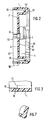
- Figur 1 einen Querschnitt durch ein erfindungsgemässes Gehäuse
- Figur 2 einen Querschnitt des Mantelteils nach Figur 1
- Figur 3 einen vergrösserten Ausschnitt der Einzelheit W aus Figur 2
- Figur 4 eine beobachterseitige Ansicht des Mantelteils nach Figur 1
- Figur 5 einen vergrösserten Ausschnitt der Einzelheit X aus Figur 4
- Figur 6 einen vergrösserten Ausschnitt der Einzelheit Y nach Figur 4
- Figur 7 einen Schnitt entlang der Linie IV-IV in Figur 4
- Figur 8 eine deckelseitige Ansicht des Mantelteils nach Figur 1
- Figur 9 einen vergrösserten Teilschnitt des Mantelteils nach Figur 1
- Figur 10 eine Ansicht des Deckglases nach Figur 1
- Figur 11 das Deckglas nach Figur 10 in der Seitenansicht
- Figur 12 die Einzelheit Z aus Figur 11 im Schnitt
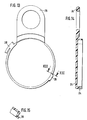
- Figur 13 eine Ansicht des Deckels nach Figur 1
- Figur 14 eine Seitenansicht des Deckels nach Figur 13 im Schnitt
- Figur 15 einen Schnitt entlang der Linie XIII-XIII in Figur 13
- Figur 16 eine Rückansicht des Deckels nach Figur 13
- Figur 17 einen vergrösserten Schnitt entlang der Linie XVI-XVI in Figur 16
- Das in den Figuren dargestellte Gehäuse besteht aus einem zylindrischen Mantelteil 1, an dem eine Tragplatte 2 angeformt ist, die das Gehäuse in einen vorderen Gehäuseinnenraum 3 und einen hinteren Gehäuseinnenraum 4 unterteilt.
- Die hintere Öffnung des Mantelteils 1 ist durch einen Deckel 5 und die beobachterseitige Öffnung 22 durch ein Deckglas 6 verschlossen.
- An der Tragplatte 2 sind Halteklammern 7 angeformt, in die Uhrwerk 8 einklipsbar ist.
- Durch eine zentrische Bohrung 9 der Tragplatte 2 ist die nicht dargestellte, auf die beobachterseitige Seite der Tragplatte 2 ragende Zeigerachse des Uhrwerks 8 hindurchgeführt.
- Zur guten Hinterlüftung liegt das Uhrwerk 8 nicht direkt auf der Tragplatte 2, sondern auf an der Tragplatte 2 angeformten Nocken 10 auf.
- Beobachterseitig ist in einem Abstand zur Tragplatte 2 ein Zifferblatt 11 angeordnet. Dieses Zifferblatt 11 liegt mittig auf einem die Mündung der Bohrung 9 umschliessenden ringförmigen Ansatz 12 der Tragplatte 11 sowie an seinem radialen Randbereich am Mantelteil 1 angeformten Abstandshaltern 13 auf und wird so auf diesem Abstand zur Tragplatte 2 gehalten.
- Die Abstandshalter 13 besitzen einen geringen Querschnitt und sind als paarweise parallel in einem Abstand zueinander verlaufende, axiale Lamellen ausgebildet. Jeweils zwei der vier Lamellenpaare liegen sich diametral gegenüber.
- Mit einem Durchmesser, der etwa dem Durchmesser des Zifferblatts 11 entspricht, sind die Lamellen bis zur beobachterseitigen Öffnung 22 des Mantelteils 1 weitergeführt und bilden von der Innenwand des Mantelteils 1 radial nach innen ragende Ansätze 14.
- Zwischen den Ansätzen 14 sind an der Innenwand des Mantelteils 1 Ausnehmungen ausgebildet, wobei die Ausnehmungen 15 an zwei sich gegenüberliegenden Lamellenpaaren bis zur Mündung der beobachterseitigen Öffnung 22 reichen, während die beiden anderen Ausnehmungen 16 vor dieser Mündung enden.
- Radial nach aussen hervorstehende Ansätze 17 des Zifferblatts 11 ragen in die Ausnehmungen 15 hinein und bilden so eine Verdrehsicherung des Zifferblatts 11.
- Ein zylindrischer Teil 18 des Deckglases 6 ist in das Mantelteil 1 eingeschoben und zwischen den Ansätzen 14 geführt. Zwei radiale vorstehende Nocken 19 des Deckglases 6 rasten in dessen Einbaulage in die Ausnehmungen 16 ein. Durch axial hervorstehende Nocken 20 kommt das Deckglas 6 am Zifferblatt 11 zur Anlage. Dadurch wird die Einschubmöglichkeit des Deckglases 6 in das Mantelteil 1 so begrenzt, dass ein Rand 21 des Deckglases 6 grösserer radialer Erstreckung als die Öffnung 22 des Mantelteils 1 nicht an der Stirnseite des Mantelteils 1 zur Anlage kommt. Damit sind für den Beobachter nicht ohne weiteres sichtbare Luftzirkulationsöffnungen gebildet, die hinter dem Rand 21 zu dem zwischen Mantelteil 1 und zylindrischen Teil 18 des Deckglases 6 und zu dem Gehäuseinnenraum führen.
- Durch die gleichzeitig Luftzirkulationsöffnung bildenden Ausnehmungen 15 und 16 ist der Gehäuseinnenraum 3 auch mit dem zwischen Tragplatte 2 und Zifferblatt 11 befindlichen Gehäuseinnenraum 23 verbunden.
- Der Deckel 5 besteht aus einem zylindrischen topfförmigen Ansatz 24, der in den Innenraum 4 hineinragt und zu diesem Innenraum 4 hin offen ist.
- Der Boden 25 dieses Ansatzes 24 steht von dem Mantelteil 1 axial hervor und ist mit einer radial wegragenden Aufhängevorrichtung 26 ausgebildet.
- Mit seiner mündungsseitigen ringförmigen Stirnfläche liegt der Ansatz 24 auf einer entsprechenden an der Tragplatte 2 angeformten Stützfläche 27 auf und hintergreift mit radial hervorste- henden Lappen 28 bajonettartig entsprechende Flächen 29 der Tragplatte 2. Auf diese Weise ist der Deckel 5 mit der Tragplatte 2 sowie dem Mantelteil 1 verbindbar. Ausnehmungen 30 in der Stützfläche 27, die radial in den Gehäuseinnenraum 4 münden, sowie in den den Ansatz 24 umschliessenden zylindrischen Teil des Mantelteils 1 ausgebildete axiale Kanäle 31, die mit einem Ende mit den Ausnehmungen 30 verbunden sind und mit dem anderen Ende nach aussen führen, bilden Luftzirkulationsöffnungen zum Belüften des Gehäuseinnenraumes 4. Diese Kanäle 31 sind durch Vertiefungen in der zylindrischen Innenwand des Mantelteils 1 gebildet.
- Durchbrüche 32 im radial äusseren Bereich der Tragplatte 2 als auch Durchbrüche 33 im Bereich der Halteklammern 7 für das Uhrwerk 8 bilden Luftzirkulationsöffnungen zwischen den Gehäuseinnenräumen 4 und 23.
- Da somit alle Gehäuseinnenräume 3, 4 und 23 untereinander verbunden sind und der Gehäuseinnenraum 3 nach der Beobachterseite und der Gehäuseinnenraum 4 nach der Rückseite Öffnungen besitzen, ist eine Luftströmung von der Vorderseite durch das ganze Gehäuse zur Rückseite hin möglich. Dadurch besteht permanent ein Luftaustausch, der einen Niederschlag von Feuchtigkeit im Gehäuse verhindert bzw. sofort wieder abbaut.
Claims (20)
Applications Claiming Priority (2)
| Application Number | Priority Date | Filing Date | Title |
|---|---|---|---|
| DE3146897 | 1981-11-26 | ||
| DE3146897A DE3146897C2 (de) | 1981-11-26 | 1981-11-26 | Gehäuse für eine Uhr |
Publications (3)
| Publication Number | Publication Date |
|---|---|
| EP0080550A2 EP0080550A2 (de) | 1983-06-08 |
| EP0080550A3 EP0080550A3 (en) | 1984-04-11 |
| EP0080550B1 true EP0080550B1 (de) | 1986-09-17 |
Family
ID=6147265
Family Applications (1)
| Application Number | Title | Priority Date | Filing Date |
|---|---|---|---|
| EP82104846A Expired EP0080550B1 (de) | 1981-11-26 | 1982-06-03 | Gehäuse für eine Uhr |
Country Status (4)
| Country | Link |
|---|---|
| US (1) | US4505598A (de) |
| EP (1) | EP0080550B1 (de) |
| CA (1) | CA1189329A (de) |
| DE (2) | DE3146897C2 (de) |
Families Citing this family (6)
| Publication number | Priority date | Publication date | Assignee | Title |
|---|---|---|---|---|
| CH684980B5 (fr) * | 1993-04-06 | 1995-08-31 | Ebauchesfabrik Eta Ag | Mouvement de montre comprenant une plaque de maintien d'un organe indicateur. |
| CH684297B5 (fr) * | 1993-04-20 | 1995-02-28 | Blancpain Sa | Boîte de montre présentant une lunette amovible. |
| US5940350A (en) * | 1997-05-20 | 1999-08-17 | Booty, Jr.; Donald J. | Water-resistant clock with suction cups |
| EA202091979A1 (ru) | 2018-03-22 | 2021-06-22 | Вайкинг Терапьютикс, Инк. | Кристаллические формы и способы получения кристаллических форм соединения |
| EP4775207A2 (de) | 2018-12-05 | 2026-07-15 | Viking Therapeutics, Inc. | Zusammensetzungen zur behandlung von fibrose |
| EP4161925A4 (de) | 2020-06-09 | 2024-09-04 | Viking Therapeutics, Inc. | Zusammensetzungen und verfahren zur behandlung von lebererkrankungen |
Family Cites Families (20)
| Publication number | Priority date | Publication date | Assignee | Title |
|---|---|---|---|---|
| BE628503A (de) * | ||||
| US1537228A (en) * | 1922-06-03 | 1925-05-12 | Western Electric Co | Means for cooling carrier-wave apparatus |
| DE1659059U (de) * | 1953-02-25 | 1953-07-16 | Schwarzwald Uhren G M B H | Zeituhr. |
| DE1787194U (de) * | 1959-02-12 | 1959-04-16 | Wilhelm Giesen | Gekapseltes signalgeraet mit akustischer signalgabe und skalenscheibe. |
| US3461663A (en) * | 1966-01-21 | 1969-08-19 | Gen Electric | Battery operated clock |
| US3376845A (en) * | 1966-03-01 | 1968-04-09 | Rebollido Terry | Anti-glare shield for a spectrophotometer |
| US3407869A (en) * | 1967-01-16 | 1968-10-29 | Perkin Elmer Corp | Instrument cooling system |
| US3582659A (en) * | 1969-06-17 | 1971-06-01 | Manuel S Dekker | Spectrophotometer circuit with linear response to absorbance |
| US3681663A (en) * | 1970-10-05 | 1972-08-01 | Brasch Mfg Co Inc | Backless electrical control panel box |
| US3702736A (en) * | 1971-06-18 | 1972-11-14 | John C Coggeshall | Spectrophotometer |
| US3837160A (en) * | 1971-08-17 | 1974-09-24 | H Hettich | Battery driven clock with a self-regulating escapement system and a plastics material housing |
| FR2201852B1 (de) * | 1972-10-05 | 1975-03-14 | Osmin Cougeu Leon | |
| DE7404510U (de) * | 1974-02-09 | 1975-08-14 | Metall Invent Sa | Stiluhr |
| JPS519871A (en) * | 1974-06-26 | 1976-01-26 | Suwa Seikosha Kk | Udedokeiyomojibanno koteikozo |
| FR2284917A1 (fr) * | 1974-09-13 | 1976-04-09 | Derot Marie Therese | Horloge ou calendrier automatique a couvercle amovible |
| DE7739144U1 (de) * | 1977-12-22 | 1979-03-08 | Gebrueder Junghans Gmbh, 7230 Schramberg | Gehäuse für eine Uhr, insbesondere dampf- und feuchtigkeitsgeschützte Uhr |
| US4282591A (en) * | 1979-03-22 | 1981-08-04 | Andreuccetti Ilio A | Light control and indicating device |
| FR2461969A1 (fr) * | 1979-07-19 | 1981-02-06 | Bossier Pierre | Horloge montee dans un support perfectionne |
| DE2937206A1 (de) * | 1979-09-14 | 1981-04-02 | Vdo Adolf Schindling Ag, 6000 Frankfurt | Messinstrumentengehaeuse |
| DE8004650U1 (de) * | 1980-02-21 | 1980-07-17 | Vdo Adolf Schindling Ag, 6000 Frankfurt | Elektrische Uhr, insbesondere Quarzuhr |
-
1981
- 1981-11-26 DE DE3146897A patent/DE3146897C2/de not_active Expired
-
1982
- 1982-06-03 EP EP82104846A patent/EP0080550B1/de not_active Expired
- 1982-06-03 CA CA000404373A patent/CA1189329A/en not_active Expired
- 1982-06-03 DE DE8282104846T patent/DE3273304D1/de not_active Expired
- 1982-06-08 US US06/386,172 patent/US4505598A/en not_active Expired - Fee Related
Also Published As
| Publication number | Publication date |
|---|---|
| DE3146897A1 (de) | 1983-08-11 |
| DE3146897C2 (de) | 1984-04-19 |
| DE3273304D1 (en) | 1986-10-23 |
| EP0080550A3 (en) | 1984-04-11 |
| US4505598A (en) | 1985-03-19 |
| CA1189329A (en) | 1985-06-25 |
| EP0080550A2 (de) | 1983-06-08 |
Similar Documents
| Publication | Publication Date | Title |
|---|---|---|
| DE69016828T2 (de) | Streulichttyp-Rauchdetektor. | |
| WO2002034994A1 (de) | Bullaugentür für eine von vorn beschickbare trommelwaschmaschine | |
| DE102015014482A1 (de) | Filterelementeinheit für einen Luftfilter mit einer zweiteiligen durch Brücken verbundenen Dichtung | |
| DE2925411C2 (de) | Magnetkompaß | |
| EP0400597B1 (de) | Lautsprecher mit Bajonettverschluss | |
| EP0035220B1 (de) | Elektroakustischer Wandler | |
| EP0068125B1 (de) | Tragbares Schutzgehäuse für elektrische und elektronische Geräte | |
| DE3146897C2 (de) | Gehäuse für eine Uhr | |
| DE60006909T2 (de) | Gerät mit elektroakustischem wandler in einer pc-platine montiert mit hilfe von halteeinrichtungen | |
| DE2044096A1 (de) | Möbel mit mindestens einer Anschlagtür | |
| DE19816322C2 (de) | Wasserzähler-Anschluß und Wasserzähler-Einheit | |
| DE19732184C1 (de) | Lautsprecherbox | |
| DE69824984T2 (de) | Schutzgehäuse für eine Leiterplatte | |
| DE849253C (de) | Lautsprecheranordnung | |
| DE19524417A1 (de) | Gehäuse für Kraftstoffilter | |
| DE3608393A1 (de) | Optischer rauchmelder | |
| DE3529453A1 (de) | Vorrichtung zum befestigen eines lautsprechers | |
| DE8134510U1 (de) | Gehäuse für eine Uhr | |
| DE202005014946U1 (de) | Druckausgleichsverschraubung | |
| DE3316327A1 (de) | Vorrichtung zum dichten befestigen eines glases auf einem element eines uhrgehaeuses | |
| DE102018116490A1 (de) | Wandhalterung zum Halten einer Fernbedienung | |
| DE1279554B (de) | Weckeruhr | |
| DE2420919C2 (de) | Einrichtung zur Verbesserung des Klanges von Lautsprechern | |
| EP0092051A2 (de) | Elektroakustischer Wandler mit zylindrischem Gehäuse | |
| CH500530A (de) | Feuchtigkeits- und staubgeschütztes Wanduhrgehäuse |
Legal Events
| Date | Code | Title | Description |
|---|---|---|---|
| PUAI | Public reference made under article 153(3) epc to a published international application that has entered the european phase |
Free format text: ORIGINAL CODE: 0009012 |
|
| AK | Designated contracting states |
Designated state(s): DE FR GB IT SE |
|
| PUAL | Search report despatched |
Free format text: ORIGINAL CODE: 0009013 |
|
| AK | Designated contracting states |
Designated state(s): DE FR GB IT SE |
|
| 17P | Request for examination filed |
Effective date: 19840216 |
|
| ITF | It: translation for a ep patent filed | ||
| GRAA | (expected) grant |
Free format text: ORIGINAL CODE: 0009210 |
|
| AK | Designated contracting states |
Kind code of ref document: B1 Designated state(s): DE FR GB IT SE |
|
| REF | Corresponds to: |
Ref document number: 3273304 Country of ref document: DE Date of ref document: 19861023 |
|
| ET | Fr: translation filed | ||
| PLBE | No opposition filed within time limit |
Free format text: ORIGINAL CODE: 0009261 |
|
| 26N | No opposition filed | ||
| PGFP | Annual fee paid to national office [announced via postgrant information from national office to epo] |
Ref country code: GB Payment date: 19900601 Year of fee payment: 9 |
|
| PGFP | Annual fee paid to national office [announced via postgrant information from national office to epo] |
Ref country code: FR Payment date: 19900608 Year of fee payment: 9 |
|
| ITTA | It: last paid annual fee | ||
| PGFP | Annual fee paid to national office [announced via postgrant information from national office to epo] |
Ref country code: SE Payment date: 19900810 Year of fee payment: 9 |
|
| PG25 | Lapsed in a contracting state [announced via postgrant information from national office to epo] |
Ref country code: GB Effective date: 19910603 |
|
| PG25 | Lapsed in a contracting state [announced via postgrant information from national office to epo] |
Ref country code: SE Effective date: 19910604 |
|
| GBPC | Gb: european patent ceased through non-payment of renewal fee | ||
| PG25 | Lapsed in a contracting state [announced via postgrant information from national office to epo] |
Ref country code: FR Effective date: 19920228 |
|
| REG | Reference to a national code |
Ref country code: FR Ref legal event code: ST |
|
| PGFP | Annual fee paid to national office [announced via postgrant information from national office to epo] |
Ref country code: DE Payment date: 19920522 Year of fee payment: 11 |
|
| PG25 | Lapsed in a contracting state [announced via postgrant information from national office to epo] |
Ref country code: DE Effective date: 19940301 |
|
| EUG | Se: european patent has lapsed |
Ref document number: 82104846.9 Effective date: 19920109 |