EP0079060B1 - Sicherheitseinrichtung für Druckelektrolyseapparate - Google Patents
Sicherheitseinrichtung für Druckelektrolyseapparate Download PDFInfo
- Publication number
- EP0079060B1 EP0079060B1 EP82110202A EP82110202A EP0079060B1 EP 0079060 B1 EP0079060 B1 EP 0079060B1 EP 82110202 A EP82110202 A EP 82110202A EP 82110202 A EP82110202 A EP 82110202A EP 0079060 B1 EP0079060 B1 EP 0079060B1
- Authority
- EP
- European Patent Office
- Prior art keywords
- pressure
- chambers
- depressurisation
- installation according
- anode
- Prior art date
- Legal status (The legal status is an assumption and is not a legal conclusion. Google has not performed a legal analysis and makes no representation as to the accuracy of the status listed.)
- Expired
Links
Images
Classifications
-
- C—CHEMISTRY; METALLURGY
- C25—ELECTROLYTIC OR ELECTROPHORETIC PROCESSES; APPARATUS THEREFOR
- C25B—ELECTROLYTIC OR ELECTROPHORETIC PROCESSES FOR THE PRODUCTION OF COMPOUNDS OR NON-METALS; APPARATUS THEREFOR
- C25B15/00—Operating or servicing cells
- C25B15/02—Process control or regulation
- C25B15/023—Measuring, analysing or testing during electrolytic production
Definitions
- the invention relates to a safety device for pressure electrolysis apparatus for producing chlorine, alkali metal hydroxide solution and hydrogen from aqueous alkali chloride solution, with devices for measuring, adjusting and regulating the pressure in the anode and cathode chambers, which are separated from one another by an ion exchange membrane.
- Processes for producing chlorine from aqueous alkali chloride solution under pressure are known. Pressures of up to 50 bar are used in the anode and cathode chambers, which are separated by a membrane. In order not to damage the membrane, the pressure difference between the anode and cathode chambers must be kept as low as possible.
- devices for measuring, adjusting and regulating the pressure in the anode and cathode chamber of the pressure electrolysis apparatus required for pressure electrolysis are known. However, these devices for regulating the pressure fail in the event of sudden disturbances in the electrolysis operation, such as those e.g.
- the invention seeks to remedy this.
- the invention solves the problem by a safety device for pressure electrolysis apparatus for the production of chlorine, alkali metal hydroxide solution and hydrogen from aqueous alkali chloride solution with a differential pressure control device for measuring, adjusting and regulating the pressure in the anode and cathode chambers, which are separated from one another by an ion exchange membrane, the anode chambers with separators for the separation of chlorine and anolyte, the cathode chambers are connected with separators for the separation of alkali and hydrogen, characterized in that the anode and cathode chambers are additionally connected to expansion vessels via expansion valves, the expansion valves being equipped with a differential pressure measuring and control device are provided.
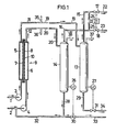
- the alkali chloride solution is fed via line 1 and pump 3 to the anode chamber 5 of the electrolytic cell 9 and water or sodium hydroxide solution to the cathode chamber 6 via line 2 and pump 4.
- the electrolytic cell 9 contains the anode 7 and the cathode 8, which are separated by an ion exchange membrane 10 .
- the anolyte with the chlorine produced is fed via lines 11 from the individual anode chambers 5 to an electrolysis cell 9 of the manifold 19 and reaches the separator 13, where the anolyte and chlorine separate.
- the hydrogen and the sodium hydroxide solution are introduced from the cathode chambers 6 via lines 12 into the collecting line 20 and the separator 14, in which the hydrogen and the alkali separate from one another.
- the gases from the separators 13 and 14 pass through lines 15 and 16, the two pressure control valves 17 and 18 and via lines 22 and 23 into downstream treatment plants (not shown).
- the two pressure control valves 17 and 18 are connected to a differential pressure control device 21 via lines 24 and 25 in such a way that, regardless of the absolute pressures, it is ensured that the pressures in the separators 13 and 14 are approximately the same.
- From the separators 13 and 14, the liquids are discharged with the aid of the level regulators 26 and 27, namely part of the alkali via line 28, line 32 and pump 4 back into the cathode chamber 6 and the other part via the control valve 30 and line 33 into the Sodium hydroxide treatment (not shown).
- the brine from the separator 13 passes via line 29 and control valve 21, which is controlled by the level controller 27, and line 34 into the dechlorination plant and brine preparation or saline station (not shown).
- the reference numerals 35 and 36 indicate pipelines with which the safety device can be connected to the manifolds 19 and 20.
- the safety device can be connected to the collecting lines 19 and 20 or to the separators 13 and 14, specifically to those shown in dashed lines Outlets 37 and 38 are connected, the connection to the separators 13 and 14 having the advantage that primarily gases and vapors would be discharged if pressure relief was required.
- the general condition is that the connection of the safety device is arranged as close as possible to the cell outlets and that there are sufficiently large flow cross-sections available for discharging the large amounts of gas everywhere in the event of a fault.
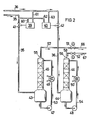
- the safety device according to FIG. 2 has two differential pressure transmitters 39 and 40 with two expansion valves 41 and 42, two expansion vessels 43 and 44, two washing columns 45 and 46, two circulation pumps 47 and 48, two coolers 49 and 50 as the differential pressure measuring and control device and two control valves 51 and 52, for example largely, regardless of the form, to the set max.
- Flow rate can be controlled or the flow increases with increasing form. Depending on the local conditions, different types of construction will be chosen.
- the pipelines 35 and 36 branch off from the collecting lines 19 and 20, which receive the starting products of the electrolysis cells 9, which contain chlorine and hydrogen. These open via controllable expansion valves 41 and 42 into the expansion vessels 43 and 44, to which washing columns 45 and 46, each designed to be pressure-resistant, are assigned. Partition walls between the expansion vessels 43 and 44 and the washing columns 45 and 46 are not required.
- the gases rising in the wash columns are separated by liquid, e.g. Alkaline chloride solution, alkaline solution or water cooled. Brine and lye are carried away, chlorine is absorbed and water vapor is deposited. This greatly reduces the total volume of the gas flows.
- the relaxation vessels 43 and 44 are simultaneously designed as a collecting container for the circulating liquids.
- the washing liquids are sucked out of the expansion vessels 43 and 44 via the lines 53 and 54, in which heat exchangers 49 and 50 can be arranged, and fed to the heads 55, 56 of the washing columns 45 and 46.
- one of the expansion valves 41 or 42 suddenly opens, as is necessary for the rapid reduction of the differential pressure, a larger amount of gas can escape into the expansion vessel 43, 44, washing column 45, 46 system. There, however, the amount of gas is spontaneously reduced, as mentioned.
- the overall system 43, 44, 45, 46 is also designed in volume so that it can buffer a sufficient amount of gas while increasing the pressure.
- the overpressure is reduced via the lines 57 and 58 and the control valves 51 and 52, in which the control valves 51 and 52 transfer a limited amount of the gases into the downstream systems, e.g. for the chlorine into a chlorine destruction, blow through lines 66, 67 (not shown). In this way, overloading of the downstream treatment plants is avoided.
- simple throttling devices can also be used, depending on the local conditions or the design of the systems.
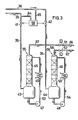
- the expansion valves 41 and 42 are opened and closed separately from one another using the differential pressure measuring and regulating device 39, 40 and 59 (FIG. 3).
- the expansion valve 41 opens when a defined differential pressure is exceeded in line 35 compared to line 36.
- the expansion valve 42 remains closed. The reverse is true if the pressure in line 36 is higher than in line 35 and this differential pressure exceeds a predetermined value.
- the expansion valve opened in each case closes again and the expansion valves 41 and 42 are closed in the normal operating state of the electrolysis system. It should be pointed out here again the different functions of the pressure holding valves 17 and 18 (FIG. 1) and the relief valves 41 and 42 of the safety device (FIGS. 2 and 3).
- the valves 17 and 18 are in constant play during the operation of the electrolysis systems, i.e. so many gases and vapors can be let through that the pressure in the electrolysis system, namely in the anode and cathode chambers 5, 6, is kept at a constant and adjusted value that is the same on both sides.
- the expansion valves 41 and 42 of the safety device are normally closed during operation of the electrolysis system and only respond when the differential pressure between the anode and cathode chambers 5 and 6 of the electrolysis cell 9 is excessive. This excessive differential pressure can occur in the event of a fault, e.g. occur when a line is torn off or when the electrolysis system is started up or shut down.
- the pressure control valves 17 and 18 are unable to compensate for the sudden pressure differences, since they have to be dimensioned for the normally occurring flow rates and the large amounts of gases and vapors cannot be processed.
- the presence of an independently operating safety device with a high blow-off capacity is advantageous for protecting the valuable systems, since, as is well known, the failure of a regulator must always be expected.
- the expansion vessels 43 and 44 can be set up spatially separate from the washing columns 45 and 46.
- the coolers 49 and 50 can be omitted if the expansion vessels 43 and 44 are designed as double-jacket vessels or are installed in these cooling coils. If large amounts of washing liquid have to be kept available, cooling may not be necessary.
- the control valves 51 and 52 should be set so that overloading of the downstream production systems is avoided.
- differential pressure transmitters 39, 40 While two differential pressure transmitters 39, 40 are provided for the safety device according to FIG. 2, the safety device according to FIG. 3 only has one differential pressure transmitter 59.
- the differential pressure transmitters are each connected via lines 60, 61, 62, 63, 64, 65 to lines 35, 36 of the safety device.
Landscapes
- Chemical & Material Sciences (AREA)
- Engineering & Computer Science (AREA)
- Organic Chemistry (AREA)
- Automation & Control Theory (AREA)
- Chemical Kinetics & Catalysis (AREA)
- Electrochemistry (AREA)
- Materials Engineering (AREA)
- Metallurgy (AREA)
- Analytical Chemistry (AREA)
- Electrolytic Production Of Non-Metals, Compounds, Apparatuses Therefor (AREA)
- Electrolytic Production Of Metals (AREA)
- Measuring Pulse, Heart Rate, Blood Pressure Or Blood Flow (AREA)
- Electrophonic Musical Instruments (AREA)
- Surface Acoustic Wave Elements And Circuit Networks Thereof (AREA)
- Fuel Cell (AREA)
- Spinning Or Twisting Of Yarns (AREA)
- Sheet Holders (AREA)
- Secondary Cells (AREA)
- Electrical Discharge Machining, Electrochemical Machining, And Combined Machining (AREA)
Description
- Die Erfindung betrifft eine Sicherheitseinrichtung für Druckelektrolyseapparate zur Herstellung von Chlor, Alkalilauge und Wasserstoff aus wässriger Alkalichloridlösung mit Einrichtungen zum Messen, Einstellen und Regeln des Druckes in den Anoden-und Kathodenkammern, die durch eine lonenaustauschermembran voneinander getrennt sind.
- Verfahren zum Herstellen von Chlor aus wässriger Alkalichloridlösung unter Druck sind bekannt. Dabei werden Drücke bis 50 bar in der Anoden- und Kathodenkammer, die durch eine Membran voneinander getrennt sind, angewendet. Um die Membran nicht zu schädigen, muss die Druckdifferenz zwischen Anoden- und Kathodenkammer möglichst gering gehalten werden. Hierfür sind Einrichtungen zum Messen, Einstellen und Regeln des Druckes in der Anoden- und Kathodenkammer der für die Druckelektrolyse erforderlichen Druckelektrolyseapparate bekannt. Diese Einrichtungen zum Regeln des Druckes versagen jedoch bei plötzlich eintretenden Störungen im Elektrolysebetrieb wie sie z.B. durch Abreissen einer Anoyltrohrleitung eintreten können, weil ein Druckausgleich zwischen den Kammern wegen der der Elektrolysezellen nachgeschalteten Aufbereitungsanlage für die Elektrolyseprodukte bei spontan absinkendem Druck in einer der Kammern nicht möglich ist. Eine ähnliche Situation wie beim Abreissen ist beim Anfahren der Elektrolyseanlage zu beobachten.
- Hier will die Erfindung Abhilfe schaffen. Die Erfindung löst die Aufgabe durch eine Sicherheitseinrichtung für Druckelektrolyseapparate zur Herstellung von Chlor, Alkalilauge und Wasserstoff aus wässriger Alkalichloridlösung mit einer Differenzdruckregeleinrichtung zum Messen, Einstellen und Regeln des Druckes in den Anoden- und Kathodenkammern, die durch eine Ionenaustauschermembran voneinander getrennt sind, wobei die Anodenkammern mit Abscheidern zur Trennung von Chlor und Anolyt, die Kathodenkammern mit Abscheidern zur Trennung von Lauge und Wasserstoff verbunden sind, dadurch gekennzeichnet, dass die Anoden- und Kathodenkammer zusätzlich über Entspannungsventile mit Entspannungsgefässen verbunden sind, wobei die Entspannungsventile mit einer Differenzdruck-mess-und -regeleinrichtung versehen sind. Den Entspannungsgefässen kann jeweils eine Kondensationseinrichtung insbesondere eine Waschkolonne zugeordnet sein. Die Differenzdruck-mess- und - regeleinrichtung kann aus einem oder zwei Differenzdruckgebern bestehen. Die Entspannungsventile sind zweckmässig mit dem Kopf der Entspannungsgefässe verbunden. Die Waschkolonnen können direkt auf den Entspannungsgefässen angeordnet sein, wobei Trennwände zwischen den Entspannungsgefässen und den Waschkolonnen nicht erforderlich sind. Dabei ist der Sumpf der Entspannungsgefässe mit dem Kopf der jeweiligen Waschkolonne durch eine Leitung verbunden, in der eine Pumpe angeordnet ist. In diesen Leitungen können jeweils Wärmetauscher angeordnet sein, und den Waschkolonnen können Drosselventile nachgeschaltet werden.
- Die durch die Erfindung erreichten Vorteile sind im wesentlichen darin zu sehen, dass bei plötzlich auftretenden Druckdifferenzen zwischen Anoden- und Kathodenkammern, diese rasch ausgeglichen werden können, ohne dass durch die damit verbundenen Gasstösse, z.B. Wasserverdampfung durch Druckentlastung, von beachtlichem Volumen weder die nachgeschaltete Aufbereitungsanlage noch die Umwelt, in die die Gase abgelassen werden müssten, belastet wird.
- Im folgenden wird die Erfindung anhand von Fliessbildern näher erläutert. Es zeigt:
- Fig. 1 eine Druckelektrolyseanlage, symbolisiert durch eine Druckelektrolysezelle mit nachgeschalteter Trennanlage für die Elektrolyseprodukte und Einrichtungen zum Messen, Einstellen und Regeln des Druckes in den Anoden- und Kathodenkammern;
- Fig. 2 die Sicherheitseinrichtung mit 2 Differenzdruckgebern;
- Fig. 3 die Sicherheitseinrichtung mit einem Differenzdruckgeber.
- Die Alkalichloridlösung wird über Leitung 1 und Pumpe 3 der Anodenkammer 5 der Elektrolysezelle 9 zugeführt und Wasser bzw. Natronlauge der Kathodenkammer 6 über Leitung 2 und Pumpe 4. Die Elektrolysezelle 9 enthält die Anode 7 und die Kathode 8, die durch eine lonenaustauschermembran 10 getrennt sind. Der Anolyt mit dem erzeugten Chlor wird über Leitungen 11 von den einzelnen Anodenkammern 5 einer Elektrolysezelle 9 der Sammelleitung 19 zugeführt und gelangt in den Abscheider 13, wo sich Anolyt und Chlor voneinander trennen. Entsprechend wird der Wasserstoff und die Natronlauge aus den Kathodenkammern 6 über Leitungen 12 in die Sammelleitung 20 und den Abscheider 14 eingebracht, in dem sich der Wasserstoff und die Lauge voneinander trennen. Die Gase aus den Abscheidern 13 und 14 gelangen über die Leitungen 15 und 16, die beiden Druckhalteventile 17 und 18 sowie über die Leitungen 22 und 23 in nachgeschaltete Anlagen zur Aufbereitung (nicht dargestellt). Die beiden Druckhalteventile 17 und 18 sind mit einer Differenzdruckregeleinrichtung 21 über Leitungen 24 und 25 verbunden und zwar so, dass unabhängig von den Absolutdrücken dafür gesorgt ist, dass die Drücke in den Abscheidern 13 und 14 annähernd gleich gross sind. Aus den Abscheidern 13 und 14 werden die Flüssigkeiten mit Hilfe der Standregler 26 und 27 abgeleitet und zwar ein Teil der Lauge über Leitung 28, Leitung 32 und Pumpe 4 zurück in die Kathodenkammer 6 und der andere Teil über das Regelventil 30 und Leitung 33 in die Natronlaugenaufbereitung (nicht dargestellt). Die Sole aus dem Abscheider 13 gelangt über Leitung 29 und Regelventil 21, das von dem Standregler 27 gesteuert wird, und Leitung 34 in die Entchlorungsanlage und Soleaufbereitung oder Salzlösestation (nicht dargestellt).
- Durch die Bezugszeichen 35 und 36 sind Rohrleitungen angedeutet, mit denen die Sicherheitseinrichtung an die Sammelleitungen 19 und 20 angeschlossen werden kann. Je nach den örtlichen Verhältnissen, Grösse der Anlage, und Einteilung des Zellenblocks, kann die Sicherheitseinrichtung an die Sammelleitungen 19 und 20 oder an die Abscheider 13 und 14, und zwar an die gestrichelt gezeichneten Abgänge 37 und 38 angeschlossen werden, wobei der Anschluss an die Abscheider 13 und 14 den Vorteil hätte, dass vornehmlich Gase und Dämpfe bei erforderlicher Druckentlastung abgeführt würden. Bedingung ist generell, dass der Anschluss der Sicherheitseinrichtung möglichst dicht bei den Zellenabgängen angeordnet ist und überall für den Störungsfall ausreichend grosse Strömungsquerschnitte zur Ableitung der grossen Gasmengen zur Verfügung stehen.
- Die Sicherheitseinrichtung nach Fig. 2 weist als Differenzdruck-mess- und -regeleinrichtung zwei Differenzdruckgeber 39 und 40 mit zwei Entspannungsventilen 41 und 42, zwei Entspannungsgefässen 43 und 44, zwei Waschkolonnen 45 und 46, zwei Umwälzpumpen 47 und 48, zwei Kühler 49 und 50 und zwei Regelventile 51 und 52 auf, die z.B. weitgehend, vom Vordruck unabhängig, auf eingestellte max. Durchgangsmenge gesteuert werden können oder deren Durchgang sich mit steigendem Vordruck vergrössert. Je nach den vorliegenden örtlichen Verhältnissen wird man verschiedene Ausführungsarten wählen.
- Von den Sammelleitungen 19 und 20, die die Ausgangsprodukte der Elektrolysezellen 9, die Chlor und Wasserstoff enthalten, aufnehmen, zweigen die Rohrleitungen 35 und 36 ab. Diese münden über regelbare Entspannungsventile 41 und 42 in die Entspannungsgefässe 43 und 44, denen jeweils druckfest ausgeführte Waschkolonnen 45 und 46 zugeordnet sind. Dabei sind Trennwände zwischen den Entspannungsgefässen 43 und 44 und den Waschkolonnen 45 und 46 nicht erforderlich. Die in den Waschkolonnen aufsteigenden Gase werden durch Flüssigkeit, z.B. Alkalichloridlösung, Alkalilauge oder Wasser gekühlt. Mitgerissene Sole und Lauge wird ausgewaschen, Chlor absorbiert und Wasserdampf niedergeschlagen. Hierdurch werden die Gesamtvolumina der Gasströme stark vermindert. Die Entspannungsgefässe 43 und 44 sind gleichzeitig als Sammelbehälter für die umlaufenden Flüssigkeiten ausgebildet. Mit Hilfe der Pumpen 47 und 48 werden die Waschflüssigkeiten über die Leitungen 53 und 54, in denen Wärmetauscher 49 und 50 angeordnet sein können, aus den Entspannungsgefässen 43 und 44 abgesaugt und den Köpfen 55, 56 der Waschkolonnen 45 und 46 zugeführt. Bei plötzlichem Öffnen eines der Entspannungsventile 41 oder 42 kann, wie es zur schnellen Verminderung des Differenzdruckes erforderlich ist, eine grössere Gasmenge in das System Entspannungsgefäss 43, 44, Waschkolonne 45, 46 entweichen. Dort wird aber die Gasmenge, wie erwähnt, spontan vermindert. Das Gesamtsystem 43, 44, 45, 46 ist ausserdem im Volumen so ausgelegt, dass es unter Drucksteigerung eine ausreichende Gasmenge abpuffern kann. Der Überdruck wird über die Leitungen 57 und 58 sowie den Regelventilen 51 und 52 abgebaut, in dem die Regelventile 51 und 52 eine bis aus ein Maximum begrenzte Menge der Gase in die nachgeschalteten Anlagen, z.B. für das Chlor in eine Chlorvernichtung, über Leitungen 66, 67 durchblasen (nicht dargestellt). Auf diese Weise wird eine Überlastung der nachgeschalteten Aufbereitungsanlagen vermieden. Anstelle der Regelventile können je nach den örtlich gegebenen Verhältnissen bzw. Auslegung der Anlagen auch einfache Drosselorgane eingesetzt werden.
- Das Öffnen und Schliessen der Entspannungsventile 41 und 42 wird getrennt voneinander mit Hilfe der Differenzdruck-mess- und -regeleinrichtung 39, 40 bzw. 59 (Fig. 3) vorgenommen. Und zwar öffnet das Entspannungsventil 41, wenn in der Leitung 35 gegenüber Leitung 36 ein festgelegter Differenzdruck überschritten wird. Das Entspannungsventil 42 bleibt dabei geschlossen. Umgekehrt ist es, wenn der Druck in der Leitung 36 höher ist als in der Leitung 35, und dieser Differenzdruck einen festgelegten Wert überschreitet. Wenn die Druckdifferenz sich verringert, schliesst das jeweils geöffnete Entspannungsventil wieder und bei normalem Betriebszustand der Elektrolyseanlage sind die Entspannungsventile 41 und 42 geschlossen. Es sei hier nochmals auf die verschiedene Funktionsweise der Druckhalteventile 17 und 18 (Fig. 1) und der Entspannungsventile 41 und 42 der Sicherheitseinrichtung (Fig. 2 und 3) hingewiesen. Die Ventile 17 und 18 sind beim Betrieb der Elektrolyseanlagen in ständigem Spiel, d.h. jedes für sich lässt soviel Gase und Dämpfe durch, dass der Druck in der Elektrolyseanlage und zwar in den Anoden- wie den Kathodenkammern 5, 6 auf einem konstanten und eingestellten, auf beiden Seiten gleichen Wert, gehalten wird. Die Entspannungsventile 41 und 42 der Sicherheitseinrichtung sind beim Betrieb der Elektrolyseanlage dagegen normalerweise geschlossen und sprechen nur bei einem überhöhten Differenzdruck zwischen der Anoden-und Kathodenkammer 5 und 6 der Elektrolysezelle 9 an. Dieser überhöhte Differenzdruck kann in einem Störungsfall, z.B. beim Abriss einer Leitung oder auch beim An- oder Abfahren der Elektrolyseanlage auftreten.
- In diesen Fällen sind die Druckhalteventile 17 und 18 nicht in der Lage die plötzliche auftretenden Druckdifferenzen auszugleichen, da sie für die normal auftretenden Durchflussmengen bemessen sein müssen und die anfallenden grossen Mengen an Gasen und Dämpfen daher nicht verarbeitet werden können. Ausserdem ist das Vorhandensein einer unabhängig arbeitenden Sicherheitseinrichtung grosser Abblaseleistung zum Schutz der wertvollen Anlagen vorteilhaft, denn mit dem Versagen eines Reglers muss bekanntlich stets gerechnet werden.
- Die Entspannungsgefässe 43 und 44 können räumlich getrennt von den Waschkolonnen 45 und 46 aufgestellt sein. Die Kühler 49 und 50 können entfallen, wenn die Entspannungsgefässe 43 und 44 als Doppelmantelgefässe ausgebildet sind oder in diese Kühlschlangen eingebaut werden. Wenn grosse Waschflüssigkeitsmengen vorgehalten werden müssen, kann unter Umständen auf eine Kühlung verzichtet werden. Die Regelventile 51 und 52 sollten so eingestellt werden, dass eine Überlastung der nachgeschalteten Produktionsanlagen vermieden wird.
- Während für die Sicherheitseinrichtung gemäss Fig. 2 zwei Differenzdruckgeber 39, 40 vorgesehen sind, weist die Sicherheitseinrichtung gemäss Fig. 3 lediglich einen Differenzdruckgeber 59 auf. Die Differenzdruckgeber sind jeweils über Leitung 60, 61, 62, 63, 64, 65 mit Leitungen 35, 36 der Sicherheitseinrichtung verbunden.
Claims (7)
Priority Applications (1)
| Application Number | Priority Date | Filing Date | Title |
|---|---|---|---|
| AT82110202T ATE17377T1 (de) | 1981-11-10 | 1982-11-05 | Sicherheitseinrichtung fuer druckelektrolyseapparate. |
Applications Claiming Priority (2)
| Application Number | Priority Date | Filing Date | Title |
|---|---|---|---|
| DE3144599 | 1981-11-10 | ||
| DE19813144599 DE3144599A1 (de) | 1981-11-10 | 1981-11-10 | "sicherheitseinrichtung fuer druckelektrolyseapparate |
Publications (2)
| Publication Number | Publication Date |
|---|---|
| EP0079060A1 EP0079060A1 (de) | 1983-05-18 |
| EP0079060B1 true EP0079060B1 (de) | 1986-01-08 |
Family
ID=6146037
Family Applications (1)
| Application Number | Title | Priority Date | Filing Date |
|---|---|---|---|
| EP82110202A Expired EP0079060B1 (de) | 1981-11-10 | 1982-11-05 | Sicherheitseinrichtung für Druckelektrolyseapparate |
Country Status (11)
| Country | Link |
|---|---|
| EP (1) | EP0079060B1 (de) |
| JP (1) | JPS5887285A (de) |
| AT (1) | ATE17377T1 (de) |
| AU (1) | AU9030382A (de) |
| BR (1) | BR8206498A (de) |
| CA (1) | CA1208164A (de) |
| DE (2) | DE3144599A1 (de) |
| ES (1) | ES517170A0 (de) |
| FI (1) | FI823827L (de) |
| NO (1) | NO823731L (de) |
| ZA (1) | ZA828193B (de) |
Family Cites Families (5)
| Publication number | Priority date | Publication date | Assignee | Title |
|---|---|---|---|---|
| US3014976A (en) * | 1960-02-29 | 1961-12-26 | Gen Electric | Fuel cell system with means for prevention of damage by differential gas pressures |
| GB1124941A (en) * | 1963-12-09 | 1968-08-21 | Brown John Constr | Improvements in or relating to control systems for electrolysers |
| JPS534796A (en) * | 1976-07-05 | 1978-01-17 | Asahi Chem Ind Co Ltd | Electrolysis of pressurized alkali halide |
| DE2727709A1 (de) * | 1977-06-21 | 1979-01-11 | Hoechst Ag | Elektrolyseapparat |
| FR2453222A1 (fr) * | 1979-04-02 | 1980-10-31 | Creusot Loire | Installation d'electrolyse de l'eau a circuits d'electrolyte regules en pression |
-
1981
- 1981-11-10 DE DE19813144599 patent/DE3144599A1/de not_active Withdrawn
-
1982
- 1982-11-05 AT AT82110202T patent/ATE17377T1/de not_active IP Right Cessation
- 1982-11-05 EP EP82110202A patent/EP0079060B1/de not_active Expired
- 1982-11-05 DE DE8282110202T patent/DE3268458D1/de not_active Expired
- 1982-11-05 ES ES517170A patent/ES517170A0/es active Granted
- 1982-11-08 FI FI823827A patent/FI823827L/fi not_active Application Discontinuation
- 1982-11-09 ZA ZA828193A patent/ZA828193B/xx unknown
- 1982-11-09 BR BR8206498A patent/BR8206498A/pt unknown
- 1982-11-09 JP JP57195411A patent/JPS5887285A/ja active Pending
- 1982-11-09 AU AU90303/82A patent/AU9030382A/en not_active Abandoned
- 1982-11-09 CA CA000415204A patent/CA1208164A/en not_active Expired
- 1982-11-09 NO NO823731A patent/NO823731L/no unknown
Also Published As
| Publication number | Publication date |
|---|---|
| BR8206498A (pt) | 1983-09-27 |
| ES8308594A1 (es) | 1983-08-01 |
| ATE17377T1 (de) | 1986-01-15 |
| ZA828193B (en) | 1983-09-28 |
| DE3268458D1 (en) | 1986-02-20 |
| NO823731L (no) | 1983-05-11 |
| FI823827A7 (fi) | 1983-05-11 |
| DE3144599A1 (de) | 1983-05-19 |
| AU9030382A (en) | 1983-05-19 |
| CA1208164A (en) | 1986-07-22 |
| FI823827L (fi) | 1983-05-11 |
| EP0079060A1 (de) | 1983-05-18 |
| ES517170A0 (es) | 1983-08-01 |
| FI823827A0 (fi) | 1982-11-08 |
| JPS5887285A (ja) | 1983-05-25 |
Similar Documents
| Publication | Publication Date | Title |
|---|---|---|
| EP3802918B1 (de) | Verfahren und vorrichtung zum bereitstellen von wenigstens einem produktstrom durch elektrolyse | |
| DE69309080T2 (de) | Kontrollverfahren für den druck in einer elektrolysevorrichtung und elektrolysevorrichtung zur herstellung von wasserstoff und sauerstoff | |
| DE3837354C2 (de) | ||
| CH668162A5 (de) | Verfahren zur sterilisierung von fluessigkeiten und anlage zur durchfuehrung des verfahrens. | |
| EP0543285B1 (de) | Vorrichtung zur Expansionsübernahme in Flüssigkeitskreislaufsystemen | |
| DE3313645C1 (de) | Den Betriebsunterdruck fuer Melkanlagen automatisch regelendes Ventil | |
| DE69309937T3 (de) | Elektrolyseapparat zur erzeugung von wasserstoff | |
| DE102012201645B4 (de) | Ausdehnungs- und entgasungsvorrichtung zum anschluss an ein kreislaufsystem, insbesondere das kreislaufsystem einer gebäudeheizung | |
| DE102010047514A1 (de) | Ausdehnungs- und Entgasungsvorrichtung zum Anschluss an ein Kreislaufsystem; Kreislaufsystem einer Gebäudeheizung und Kältekreislaufsystem mit Ausdehnungs- und Entgasungsvorrichtungen | |
| DE2922281A1 (de) | Verfahren zur kontinuierlichen entgasung von wasser | |
| DE2806656C2 (de) | Wärmespeicheranlage | |
| EP0079060A1 (de) | Sicherheitseinrichtung für Druckelektrolyseapparate | |
| DE2304700A1 (de) | Druckwasserreaktor | |
| EP0902239A2 (de) | Flüssigkeitsgesteuerte Druckhaltevorrichtung | |
| DE577443C (de) | Betriebssicherung an Druckzersetzeranlagen, insbesondere fuer Wasserzersetzung | |
| DE900695C (de) | Sicherungseinrichtung fuer Druckzersetzer | |
| DE3039227C2 (de) | Verfahren zur Einschränkung von Betriebsstörungsauswirkungen im Atomkraftwerk und Anlage zu dessen Durchführung | |
| AT90831B (de) | Schutzgasselbstschluß- und Reglerventil an Gasleitungen explosionssicherer Lagerungen für feuergefährliche Flüssigkeiten. | |
| AT125888B (de) | Einrichtung zur Regelung des Elektrolytumlaufs bei Druckzersetzern mit getrenntem Anolyt- und Katholyt-Umlauf. | |
| DE509933C (de) | Einrichtung zur Regelung des Elektrolytumlaufs bei Druckzersetzern mit getrenntem Anolyt- und Katolyt-Umlauf | |
| DE603450C (de) | OElgefuellte elektrische Kabelanlage | |
| DE4431506C1 (de) | Schaltung von Sicherheitsventilen | |
| DE394008C (de) | Anlage zur Speisung von Dampfkesseln mit Kondensaten aus einem den Kondensaten gemeinsamen Sammelbehaelter | |
| DE110271C (de) | ||
| DE910998C (de) | Verfahren und Einrichtung zur Trennung von Fluessigkeitsgemischen |
Legal Events
| Date | Code | Title | Description |
|---|---|---|---|
| PUAI | Public reference made under article 153(3) epc to a published international application that has entered the european phase |
Free format text: ORIGINAL CODE: 0009012 |
|
| AK | Designated contracting states |
Designated state(s): AT BE CH DE FR GB IT LI NL SE |
|
| 17P | Request for examination filed |
Effective date: 19831022 |
|
| GRAA | (expected) grant |
Free format text: ORIGINAL CODE: 0009210 |
|
| AK | Designated contracting states |
Designated state(s): AT BE CH DE FR GB IT LI NL SE |
|
| REF | Corresponds to: |
Ref document number: 17377 Country of ref document: AT Date of ref document: 19860115 Kind code of ref document: T |
|
| ITF | It: translation for a ep patent filed | ||
| REF | Corresponds to: |
Ref document number: 3268458 Country of ref document: DE Date of ref document: 19860220 |
|
| ET | Fr: translation filed | ||
| PLBE | No opposition filed within time limit |
Free format text: ORIGINAL CODE: 0009261 |
|
| STAA | Information on the status of an ep patent application or granted ep patent |
Free format text: STATUS: NO OPPOSITION FILED WITHIN TIME LIMIT |
|
| 26N | No opposition filed | ||
| PGFP | Annual fee paid to national office [announced via postgrant information from national office to epo] |
Ref country code: CH Payment date: 19911021 Year of fee payment: 10 |
|
| PGFP | Annual fee paid to national office [announced via postgrant information from national office to epo] |
Ref country code: FR Payment date: 19911022 Year of fee payment: 10 |
|
| PGFP | Annual fee paid to national office [announced via postgrant information from national office to epo] |
Ref country code: SE Payment date: 19911024 Year of fee payment: 10 Ref country code: GB Payment date: 19911024 Year of fee payment: 10 Ref country code: AT Payment date: 19911024 Year of fee payment: 10 |
|
| PGFP | Annual fee paid to national office [announced via postgrant information from national office to epo] |
Ref country code: BE Payment date: 19911113 Year of fee payment: 10 |
|
| ITTA | It: last paid annual fee | ||
| PGFP | Annual fee paid to national office [announced via postgrant information from national office to epo] |
Ref country code: NL Payment date: 19911130 Year of fee payment: 10 |
|
| PGFP | Annual fee paid to national office [announced via postgrant information from national office to epo] |
Ref country code: DE Payment date: 19920115 Year of fee payment: 10 |
|
| PG25 | Lapsed in a contracting state [announced via postgrant information from national office to epo] |
Ref country code: GB Effective date: 19921105 Ref country code: AT Effective date: 19921105 |
|
| PG25 | Lapsed in a contracting state [announced via postgrant information from national office to epo] |
Ref country code: SE Effective date: 19921106 |
|
| PG25 | Lapsed in a contracting state [announced via postgrant information from national office to epo] |
Ref country code: LI Effective date: 19921130 Ref country code: CH Effective date: 19921130 Ref country code: BE Effective date: 19921130 |
|
| BERE | Be: lapsed |
Owner name: HOECHST A.G. Effective date: 19921130 |
|
| PG25 | Lapsed in a contracting state [announced via postgrant information from national office to epo] |
Ref country code: NL Effective date: 19930601 |
|
| GBPC | Gb: european patent ceased through non-payment of renewal fee |
Effective date: 19921105 |
|
| NLV4 | Nl: lapsed or anulled due to non-payment of the annual fee | ||
| PG25 | Lapsed in a contracting state [announced via postgrant information from national office to epo] |
Ref country code: FR Effective date: 19930730 |
|
| REG | Reference to a national code |
Ref country code: CH Ref legal event code: PL |
|
| PG25 | Lapsed in a contracting state [announced via postgrant information from national office to epo] |
Ref country code: DE Effective date: 19930803 |
|
| REG | Reference to a national code |
Ref country code: FR Ref legal event code: ST |
|
| EUG | Se: european patent has lapsed |
Ref document number: 82110202.7 Effective date: 19930610 |