EP0078694B1 - Method of producing elongate large-size forged article - Google Patents
Method of producing elongate large-size forged article Download PDFInfo
- Publication number
- EP0078694B1 EP0078694B1 EP82305795A EP82305795A EP0078694B1 EP 0078694 B1 EP0078694 B1 EP 0078694B1 EP 82305795 A EP82305795 A EP 82305795A EP 82305795 A EP82305795 A EP 82305795A EP 0078694 B1 EP0078694 B1 EP 0078694B1
- Authority
- EP
- European Patent Office
- Prior art keywords
- ingot
- forging
- rotor shaft
- diameter
- niobium
- Prior art date
- Legal status (The legal status is an assumption and is not a legal conclusion. Google has not performed a legal analysis and makes no representation as to the accuracy of the status listed.)
- Expired
Links
Images

Classifications
-
- C—CHEMISTRY; METALLURGY
- C21—METALLURGY OF IRON
- C21D—MODIFYING THE PHYSICAL STRUCTURE OF FERROUS METALS; GENERAL DEVICES FOR HEAT TREATMENT OF FERROUS OR NON-FERROUS METALS OR ALLOYS; MAKING METAL MALLEABLE, e.g. BY DECARBURISATION OR TEMPERING
- C21D8/00—Modifying the physical properties of ferrous metals or ferrous alloys by deformation combined with, or followed by, heat treatment
-
- C—CHEMISTRY; METALLURGY
- C21—METALLURGY OF IRON
- C21D—MODIFYING THE PHYSICAL STRUCTURE OF FERROUS METALS; GENERAL DEVICES FOR HEAT TREATMENT OF FERROUS OR NON-FERROUS METALS OR ALLOYS; MAKING METAL MALLEABLE, e.g. BY DECARBURISATION OR TEMPERING
- C21D7/00—Modifying the physical properties of iron or steel by deformation
- C21D7/13—Modifying the physical properties of iron or steel by deformation by hot working
-
- C—CHEMISTRY; METALLURGY
- C21—METALLURGY OF IRON
- C21D—MODIFYING THE PHYSICAL STRUCTURE OF FERROUS METALS; GENERAL DEVICES FOR HEAT TREATMENT OF FERROUS OR NON-FERROUS METALS OR ALLOYS; MAKING METAL MALLEABLE, e.g. BY DECARBURISATION OR TEMPERING
- C21D9/00—Heat treatment, e.g. annealing, hardening, quenching or tempering, adapted for particular articles; Furnaces therefor
- C21D9/38—Heat treatment, e.g. annealing, hardening, quenching or tempering, adapted for particular articles; Furnaces therefor for roll bodies
-
- C—CHEMISTRY; METALLURGY
- C22—METALLURGY; FERROUS OR NON-FERROUS ALLOYS; TREATMENT OF ALLOYS OR NON-FERROUS METALS
- C22C—ALLOYS
- C22C38/00—Ferrous alloys, e.g. steel alloys
- C22C38/18—Ferrous alloys, e.g. steel alloys containing chromium
- C22C38/26—Ferrous alloys, e.g. steel alloys containing chromium with niobium or tantalum
-
- Y—GENERAL TAGGING OF NEW TECHNOLOGICAL DEVELOPMENTS; GENERAL TAGGING OF CROSS-SECTIONAL TECHNOLOGIES SPANNING OVER SEVERAL SECTIONS OF THE IPC; TECHNICAL SUBJECTS COVERED BY FORMER USPC CROSS-REFERENCE ART COLLECTIONS [XRACs] AND DIGESTS
- Y10—TECHNICAL SUBJECTS COVERED BY FORMER USPC
- Y10T—TECHNICAL SUBJECTS COVERED BY FORMER US CLASSIFICATION
- Y10T29/00—Metal working
- Y10T29/49—Method of mechanical manufacture
- Y10T29/4998—Combined manufacture including applying or shaping of fluent material
- Y10T29/49988—Metal casting
Definitions
- the present invention relates to a method of producing a forged article suitable for use as the rotor shaft of a steam turbine.
- alloy steels used as the material of an elongate large-size forged article for use at high temperature, in particular a rotor shaft of a steam turbine contain about 10 wt% of chromium and a small amount of niobium.
- Such alloy steels are described, for example, US-A-3,739,337.
- the ingot In the production of an elongate large-size forged article, the ingot is usually formed so as to have a height which is larger than its diameter, because such a form of the ingot reduces the number of steps in the forging process. More specifically, the ratio H/D of the height H to the diameter D of the ingot, neglecting the hot top portion, is selected usually in the range between 1.5 and 2.0, measuring the diameter D at the heightwise mid-point of the ingot.
- the solidification in the core portion of the ingot takes place last, so that V-segregation and/or a shrinkage cavity are formed in the core portion of the ingot, while sedimental crystals tend to be generated in the lower portion of the ingot.
- the ingot is made by means of a metal mold, the V-segregation and shrinkage cavity tend to be formed in large ingots having a diameter exceeding 500 mm.
- the shrinkage cavity is referred to also as loose structure.
- the portion of the ingot containing the sedimental crystals is cut and removed because such a portion includes large non-metallic inclusions which adversely affect the mechanical properties of the product.
- an object of the invention is to provide a method of producing, from an alloy steel containing about 0.1 wt% of niobium and about 10 wt% of chromium, a rotor shaft of a steam turbine from which the eutectic niobium carbides and sedimental crystals are excluded.
- the invention is set out in claim 1.
- the ingot used in the invention exhibits a greater solidification rate at the radially outer part than at the radially central part, and at the axially lower part than at the axially upper part.
- the ingot in accordance with the invention having a height to diameter ratio H/D of not greater than 1 as measured substantially at the heightwise mid-point can effectively avoid the formation of the sedimental crystals. This in turn makes it possible to use the whole of the ingot as the forged article.
- the portion of the ingot neglecting the hot top portion will be referred to as the "body" of the ingot, herein. If the alloy steel has a too high niobium content, eutectic niobium carbides often remain in the ingot even if the height to diameter ratio H/D takes a value not greater than 1, so that the upper limit of the niobium content is restricted to 0.15 wt%.
- alloy steels having the following compositions can suitably be used as the material of the rotor shaft of steam turbine: 0.08 to 0.25 wt% of carbon, 0.15 to 0.3 wt% in total of carbon and nitrogen, not greater than 0.5 wt% of silicon, 0.4 to 1 wt% of manganese, 9 to 12 wt% of chromium, 0.7 to 1.5 wt% of molybdenum, 0.15 to 0.3 wt% of vanadium, 0.02 to 0.15 wt% of niobium and the balance iron and, optionally, not greater than 1 wt% of nickel.
- the present invention can be used quite suitably for the production of a rotor shaft from, for example, the 12 wt% chromium alloy steel mentioned above.
- At least 0.02 wt% of niobium is essential for increasing the mechanical strength of the alloy steel, particularly high temperature strength.
- a too high niobium content will unfavourably cause eutectic niobium carbides in the ingot, so that the upper limit of the niobium content is selected to be 0.15 wt%.
- Chromium is essential for increasing the oxidation resistance as well as the strength but tends to form delta ferrite to reduce the impact value, elongation and the reduction of area. The chromium content, therefore, should be in the range between 9 and 12 wt%. Molybdenum and vanadium contribute to the increase in the high temperature strength.
- the molybdenum content and the vanadium content should be selected to fall within the above-mentioned ranges because they tend to promote the formation of ferrite.
- Silicon and manganese are elements which are usually present in alloy steels of the kind described.
- the silicon content should be selected to be not greater than 0.5 wt% because an excessively high silicon content promotes the generation of ferrite making the material brittle.
- manganese promotes the formation of austenite
- the manganese content should also be selected not to be higher than 1 wt% because a too high manganese content will reduce the high temperature strength.
- the nickel may or not may be present.
- the nickel content should not exceed 1 wt% because nickel tends to reduce the high temperature strength although it promotes the austenite stabilization.
- Carbon which is an element effective for increasing the strength, tends to increase the amount of carbides, making the material brittle and reducing the high temperature strength if the carbon content is too high.
- the carbon content therefore, should be selected in the range between 0.08 and 0.25 wt%.
- An addition of a small amount of nitrogen serves to increase the high temperature strength.
- the carbon content and nitrogen content in total should be selected in the range between 0.15 and 0.3 wt%.
- the alloy steel from which the forged article of the invention is produced should not contain other elements than those mentioned above. If some other elements are unavoidably present, the content of such elements in total should not exceed 1 wt%.
- Both the phosphorus content and the sulfur content are preferably maintained at levels not greater than 0.015 wt%.
- the sulfur content should be selected not to exceed 0.005 wt%, because the sulfur inconveniently promotes the generation of eutectic niobium carbides.
- the chromium equivalent of the alloy steel preferably ranges between 5.0 and 6.5. Higher chromium equivalent produces greater amount of delta ferrite, making the material more brittle. In contrast, a too low chromium equivalent reduces the strength.
- the chromium equivalent is calculated employing the following numerical values.
- the rotor shaft of the steam turbine is typically produced by a process having the following steps (1) to (8).
- a test and inspection are conducted between each successive pair of steps.
- the preferred practical method and condition for carrying out each step will be explained below.
- the amounts of constituents are adjusted to provide the desired composition of the alloy steel.
- the constituents are then melted in an electric furnace and refined.
- the addition of nitrogen, however, is made later in the next step, i.e. the ladle refining, for otherwise the nitrogen may be released into the atmosphere during the vacuum degassing process.
- the molten metal is further refined in a ladle to get rid of oxygen, sulfur and hydrogen.
- a vacuum degassing is conducted under vacuum of 1 mmHg or less.
- the molten metal is poured into and solidified in a metal mold which is shaped and dimensioned to provide a ratio H/D between the height H of the ingot neglecting the hot top portion and the diameter D of the ingot as measured at its heightwise mid point, i.e. the point of 1/2 H from the bottom takes a value not greater than 1.
- the ratio H/D between the height H and the diameter D preferably ranges between 0.5 and 1.0, more preferably between 0.8 and 1.0. A value of the ratio H/D smaller than 0.5 will make it difficult to carry out the forging in the next step.
- the metal mold used in the invention should have side walls and bottom wall made of metal, although the hot top portion may be made of a heat insulating material such as bricks or sand mold.
- the solidification starts with the portion contacting the metal mold.
- the concentration of niobium is substantially uniform over the entire portion of the molten metal but, as the solidification goes on, the niobium content is increased at the central portion of the molten metal in the metal mold.
- the height to diameter ratio H/D takes a large value, the solidification rate at the heightwise central portion of the ingot becomes larger than that in the upper portion of the ingot, so that the solidification in the heightwise central portion is completed to confine eutectic niobium carbides and non-metallic inclusions in the above-mentioned heightwise central portion. This is the reason why the eutectic niobium carbides become present in the core portion of the ingot.
- the solidification rate at the above-mentioned heightwise central portion can be decreased by decreasing the value of the ratio H/D.
- the height to diameter ratio H/D most preferably is in the range between 0.8 and 1.0.
- the ingot making step is conducted preferably under a vacuum of 50 mmHg or less.
- the invention it is possible to reduce the number of cycles of upsetting forging or to completely eliminate the upsetting forging because the core portion of the ingot can have no eutectic NbC nor any defect such as shrinkage cavity. Furthermore, it is not necessary to cut the bottom portion of the ingot because no sedimental crystals are generated in the bottom portion of the ingot.
- the forging process containing one cycle of upsetting forging is conducted, at first the forging is conducted to compress the ingot in the radial direction and then an upsetting forging is conducted followed by another radial forging. In this way, the heightwise length of the ingot is gradually increased while the radial dimension is gradually decreased. It is not preferred to effect the forging in such a manner as to reduce the heightwise length of the ingot while increasing the radial dimension. In the case where the forging is effected in such a manner, the quality of the forged article fluctuates along the length of the forged article. Such an article is not suitable for use as the material of steam turbine rotor shaft.
- the forged article is subjected to an annealing, preferably to a full annealing.
- the forged and annealed article is then machined by a cutting tool or the like into the size and form approximating to those of the final product, i.e. the rotor shaft thereby to facilitate the cutting after the final heat treatment.
- the rotor shaft is examined by means of, for example, an ultrasonic flaw detector after the machining.
- a hardening and tempering are effected on the rotor shaft.
- the hardening temperature preferably ranges between 1000 and 1100°C, while the tempering temperature preferably ranges between 550 and 680°C. It is also preferred to rotate the rotor shaft in the circumferential direction, in order to attain uniform heating of the forged article.
- the steel ingot is machined again into the rotor shaft having final shape and size.
- the ingot has a hot top portion annexed to an upper portion thereof. After the ingot production, the hot top portion is severed and cut off from the ingot.
- the ingot has an inversely tapered form for an easier separation from the metal mold, and the diameter D of the ingot at the heightwise mid point of the ingot after the separation of the hot top portion, i.e. at the heightwise mid portion of the body of the ingot, substantially coincides with the mean diameter of the ingot.
- the body of the ingot has a cross-section which is of circular form or corrugated circular form or a rectangular form approximating circular form. It is, therefore, possible to determine the diameter D assuming the cross-section as being circular.
- An ingot having a diameter of about 500 mm was made from an alloy steel containing 0.02 to 0.15 wt% of niobium and 9 to 12 wt% of chromium, and was examined to investigate at which portion of the ingot the eutectic niobium carbides are concentrated. More specifically, the composition of this alloy steel was as follows: 0.17 wt% C, 0.30 wt% Si, 0.75 wt% Mn, 0.007 wt% P, 0.003 wt% S, 0.55 wt% Ni, 10.6 wt% Cr, 0.98 wt% Mo, 0.19 wt% V, 0.08 wt% Nb, 0.06 wt% N and the balance Fe.
- the solidification completion time for completing the solidification of the ingot and the temperature gradient at the time of completion of solidification were determined through calculation.
- Figure 1 shows the solidification time (hr) at a predetermined portion of 12 wt% chromium steel ingot having a height to diameter ratio H/D of 1.35 and a weight of 100 tons.
- the numerals in the drawings show the solidification time (hr) while the curves show the solidification front attained at predetermined times.
- Figure 2 shows the temperature gradient (unit °C/cm) in the ingot at the time of completion of solidification.
- the temperature gradient at the time of completion of solidification is comparatively small in the accelerated solidification region.
- Figure 3 illustrates the solidification completion line and solidification completion time (hr) as observed in the ingot molded from about 100 tons of 12 wt% chromium alloy steel having a height to diameter ratio H/D of 1.0.
- the composition of this alloy steel is identical to that of the alloy steel explained in connection with Figures 1 and 2.
- the pitch of the solidification completion lines at the core portion of the ingot is much smaller than that shown in Figure 1.
- Figure 4 shows the temperature gradient (°C/cm) of the same ingot as that shown in Figure 3 as observed at the time of completion of the solidification. In Figure 4, the small region of small temperature gradient as shown in Figure 2 cannot be seen in the core portion of the ingot.
- This value 1.0 of the height to diameter ratio H/D is the upper limit value for preventing generation of V-segregation and shrinkage cavity in the central region of the large-size ingot. Namely, it has proved that the V-segregation and the shrinkage cavity are generated when the ratio H/D takes a value exceeding 1.0, whereas no V-segregation and shrinkage cavity are formed nor the eutectic niobium carbides exist when the height to diameter ratio H/D takes a value smaller than 1.0.
- the generation of defects is suppressed further to provide higher internal quality of the product as the value of the height to diameter ratio H/D is decreased but a smaller value of the ratio H/D makes the subsequent forging operation difficult. With a view to forging, it is not preferred to reduce the value of the ratio H/D down below 0.5.
- the height to diameter ratio H/D takes a value preferably ranging between 1.0 and 0.5, in order to avoid the presence of any eutectic niobium carbides.
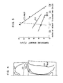
- Figure 5 shows the result of calculation executed to examine how the temperature gradient at the time of completion of solidification in the portion having generation of eutectic NbC varies with the height to diameter ratio H/D and the weight of the ingot.
- the area shown at the left side of the broken line represents the region having no eutectic NbC, whereas the area at the right side of the broken line is the region where the eutectic NbC exists. It is clear that, in the case of a large-size ingot, the eutectic NbC does not remain in the body of the ingot if the ratio H/D takes a value not greater than 1.0.
- Ingots of about 13 tons and 10 tons, respectively, and having the height to diameter ratio H/D of 0.8 were formed from a 12 wt% chromium steel containing 0.17 wt% of C, 0.35 wt% of Si, 0.75 wt% of Mn, 11.0 wt% of Cr, 1.0 wt% of Mo, 0.2 wt% of V, 0.5 wt% of Ni, 0.06 wt% of N and the balance Fe.
- a macroscopic etching test was conducted with the 13 tons ingot. As a result, it was proved that this ingot was sound having no V-segregation and no shrinkage cavity, although slight microporosity was found.
- An ingot of about 100 tons and having the height to diameter ratio H/D of 0.96 was made using a metal mold, and a turbine rotor shaft was produced from this ingot.
- the composition of the ingot was same as in the Embodiment 1.
- the constituents except the nitrogen were melted in an electric furnace and were degassed under a vacuum of 1 mmHg or less in a ladle and then nitrogen was added to the molten metal. Subsequently, the molten metal was poured into the metal mold in an atmosphere of a vacuum of 20 to 30 mmHg at a temperature of between 1590 and 1610°C to obtain an ingot having a diameter of 2400 mm.
- the ingot was then forged at a temperature of 1150°C to reduce the diameter to 1300 mm.
- the forging process applied included one cycle of upsetting forging and two cycles of radially compressing forging.
- the ingot was subjected to a full annealing and, after a cutting by a cutting tool, subjected to a hardening/tempering treatment.
- the hardening temperature and tempering temperature ranged between 1000 and 1100°C and between 550 and 630°C, respectively.
- the thus treated material was then subjected to an ultrasonic testing, measurement of mechanical property and magnetic particle testing. No defect was detected by the ultrasonic testing.
- the measurement of the mechanical properties was made with test pieces cut out from the rotor shaft material. The test results are shown in Table 1, from which it will be seen that both of the surface portion and the core portion of the rotor shaft have good mechanical properties.
- the magnetic particle testing was conducted by forming a bore of 127 mm dia. at the center of the rotor shaft but no defect was detected.
- a finish machining was conducted by means of a cutting tool to complete a rotor shaft having the maximum diameter of 1175 mm and overall length of 7980 mm.
Landscapes
- Chemical & Material Sciences (AREA)
- Engineering & Computer Science (AREA)
- Mechanical Engineering (AREA)
- Materials Engineering (AREA)
- Metallurgy (AREA)
- Organic Chemistry (AREA)
- Crystallography & Structural Chemistry (AREA)
- Physics & Mathematics (AREA)
- Thermal Sciences (AREA)
- Forging (AREA)
- Refinement Of Pig-Iron, Manufacture Of Cast Iron, And Steel Manufacture Other Than In Revolving Furnaces (AREA)
- Turbine Rotor Nozzle Sealing (AREA)
Applications Claiming Priority (2)
| Application Number | Priority Date | Filing Date | Title |
|---|---|---|---|
| JP56174635A JPS5877743A (ja) | 1981-11-02 | 1981-11-02 | ニオビウムを含有する合金鋼の造塊法 |
| JP174635/81 | 1981-11-02 |
Publications (3)
| Publication Number | Publication Date |
|---|---|
| EP0078694A2 EP0078694A2 (en) | 1983-05-11 |
| EP0078694A3 EP0078694A3 (en) | 1984-05-16 |
| EP0078694B1 true EP0078694B1 (en) | 1987-02-04 |
Family
ID=15982034
Family Applications (1)
| Application Number | Title | Priority Date | Filing Date |
|---|---|---|---|
| EP82305795A Expired EP0078694B1 (en) | 1981-11-02 | 1982-11-01 | Method of producing elongate large-size forged article |
Country Status (6)
| Country | Link |
|---|---|
| US (1) | US4404041A (enExample) |
| EP (1) | EP0078694B1 (enExample) |
| JP (1) | JPS5877743A (enExample) |
| KR (1) | KR890005095B1 (enExample) |
| DE (1) | DE3275389D1 (enExample) |
| IN (1) | IN157157B (enExample) |
Families Citing this family (8)
| Publication number | Priority date | Publication date | Assignee | Title |
|---|---|---|---|---|
| DE3512777A1 (de) * | 1985-04-10 | 1986-10-30 | Berchem & Schaberg Gmbh, 4650 Gelsenkirchen | Verwendung eines stahles mit zumindest 1% kohlenstoff und zumindest einem carbidbildenden legierungselement fuer baumaschinen-maschinenteile |
| DE3668009D1 (de) * | 1985-07-09 | 1990-02-08 | Mitsubishi Heavy Ind Ltd | Hochtemperaturrotor fuer eine dampfturbine und verfahren zu seiner herstellung. |
| US4762577A (en) * | 1987-01-30 | 1988-08-09 | Westinghouse Electric Corp. | 9 Chromium- 1 molybdenum steel alloy having superior high temperature properties and weldability, a method for preparing same and articles fabricated therefrom |
| JP3315800B2 (ja) * | 1994-02-22 | 2002-08-19 | 株式会社日立製作所 | 蒸気タービン発電プラント及び蒸気タービン |
| FI125577B (en) * | 2006-06-22 | 2015-11-30 | Wärtsilä Finland Oy | A method for handling a crankshaft |
| WO2013041043A1 (zh) * | 2011-09-22 | 2013-03-28 | 中国科学院金属研究所 | 一种高效率愈合钢锭或坯料内部孔洞型缺陷的锻造方法 |
| CN114632901B (zh) * | 2022-03-18 | 2024-05-17 | 西安聚能高温合金材料科技有限公司 | 一种超超临界火电机组用高温合金自由锻棒坯制备方法 |
| CN116219130B (zh) * | 2023-03-08 | 2026-01-27 | 武钢集团襄阳重型装备材料有限公司 | 一种控制锻材白点的生产方法 |
Family Cites Families (12)
| Publication number | Priority date | Publication date | Assignee | Title |
|---|---|---|---|---|
| US1150401A (en) * | 1915-05-05 | 1915-08-17 | Benjamin Talbot | Treating iron and steel ingots. |
| US1734930A (en) * | 1927-12-22 | 1929-11-05 | Gen Electric | Temperature-stabilized shaft for turbines and method of making the same |
| US3151979A (en) * | 1962-03-21 | 1964-10-06 | United States Steel Corp | High strength steel and method of treatment thereof |
| US3139337A (en) * | 1962-05-31 | 1964-06-30 | Gen Electric | Alloys |
| US3311972A (en) * | 1964-08-17 | 1967-04-04 | Int Nickel Co | Production of ingots for wrought metal products |
| AT304999B (de) * | 1970-10-15 | 1973-02-12 | Boehler & Co Ag Geb | Verfahren zur Herstellung von geschmiedetem oder gewalztem Stabstahl aus ledeburitischen Werkzeugstählen |
| US4026727A (en) * | 1975-11-04 | 1977-05-31 | A. Finkl & Sons Company | Fatigue resistant steel, machinery parts and method of manufacture thereof |
| DE2940473A1 (de) * | 1978-04-07 | 1981-01-15 | Nippon Steel Corp | Verfahren und vorrichtung zur herstellung von metallprofilen |
| JPS54146211A (en) * | 1978-05-09 | 1979-11-15 | Toshiba Corp | High and low pressure unified type turbine rotor |
| ES482396A1 (es) * | 1978-08-04 | 1980-04-01 | Creusot Loire | Procedimiento de fabricacion de lingotes de forja |
| US4286986A (en) * | 1979-08-01 | 1981-09-01 | Allegheny Ludlum Steel Corporation | Ferritic stainless steel and processing therefor |
| JPS5623367A (en) * | 1979-08-01 | 1981-03-05 | Hitachi Ltd | Production of rotor shaft |
-
1981
- 1981-11-02 JP JP56174635A patent/JPS5877743A/ja active Pending
-
1982
- 1982-10-22 KR KR8204742A patent/KR890005095B1/ko not_active Expired
- 1982-10-29 US US06/437,537 patent/US4404041A/en not_active Expired - Fee Related
- 1982-10-30 IN IN1284/CAL/82A patent/IN157157B/en unknown
- 1982-11-01 EP EP82305795A patent/EP0078694B1/en not_active Expired
- 1982-11-01 DE DE8282305795T patent/DE3275389D1/de not_active Expired
Also Published As
| Publication number | Publication date |
|---|---|
| IN157157B (enExample) | 1986-02-01 |
| KR890005095B1 (ko) | 1989-12-11 |
| KR840001862A (ko) | 1984-06-07 |
| DE3275389D1 (en) | 1987-03-12 |
| EP0078694A3 (en) | 1984-05-16 |
| JPS5877743A (ja) | 1983-05-11 |
| EP0078694A2 (en) | 1983-05-11 |
| US4404041A (en) | 1983-09-13 |
Similar Documents
| Publication | Publication Date | Title |
|---|---|---|
| US4340432A (en) | Method of manufacturing stainless ferritic-austenitic steel | |
| JPH07232256A (ja) | マルテンサイト熱間加工工具鋼ダイブロック物体及び製造方法 | |
| EP0078694B1 (en) | Method of producing elongate large-size forged article | |
| JP2018176241A (ja) | 機械構造用鋼材の製造方法 | |
| JP2707839B2 (ja) | マルテンサイト系継目無鋼管とその製造方法 | |
| RU2156312C1 (ru) | Способ производства катаных заготовок | |
| AU2004280023A1 (en) | Method for producing steel ingot | |
| US4376650A (en) | Hot workability of an age hardenable nickle base alloy | |
| JPH0790471A (ja) | 高Mn・高Nオーステナイト系ステンレス鋼鋳片の製造方法及び鋳片 | |
| JPH0676643B2 (ja) | 加工性のすぐれた高強度鋼線材 | |
| DE69938617T2 (de) | Stahl für Giessformen und Verfahren zur Herstellung | |
| JP3671868B2 (ja) | 高Cr含有鋼の鋳造方法 | |
| JPS6219253B2 (enExample) | ||
| JP3554283B2 (ja) | 表面性状に優れたFe−Ni系合金およびその製造方法 | |
| JP7563626B2 (ja) | 鋼鋳片、連続鋳造方法及び、鋼鋳片の製造方法 | |
| JPH04111962A (ja) | 高速度工具鋼の製造方法 | |
| JPH04111963A (ja) | 塑性加工用金型鋼の製造方法 | |
| KR102103382B1 (ko) | 강재 및 그 제조방법 | |
| EP0117932B1 (en) | Improving the hot workability of an age hardenable nickel base alloy | |
| Benhamou et al. | Application of directional solidification ingot (LSD) in forging of PWR reactor vessel heads | |
| JPH0521668B2 (enExample) | ||
| US1546881A (en) | Zirconium steel and process of making same | |
| CN121373258A (zh) | 一种超纯净低压转子锻件成型方法 | |
| JPH0957412A (ja) | 鋳片の表面割れを防止した連続鍛圧法 | |
| CN120174206A (zh) | 一种十吨级17-4ph沉淀硬化马氏体不锈钢的生产制造工艺 |
Legal Events
| Date | Code | Title | Description |
|---|---|---|---|
| PUAI | Public reference made under article 153(3) epc to a published international application that has entered the european phase |
Free format text: ORIGINAL CODE: 0009012 |
|
| AK | Designated contracting states |
Designated state(s): DE FR |
|
| PUAL | Search report despatched |
Free format text: ORIGINAL CODE: 0009013 |
|
| AK | Designated contracting states |
Designated state(s): DE FR |
|
| 17P | Request for examination filed |
Effective date: 19841015 |
|
| GRAA | (expected) grant |
Free format text: ORIGINAL CODE: 0009210 |
|
| AK | Designated contracting states |
Kind code of ref document: B1 Designated state(s): DE FR |
|
| REF | Corresponds to: |
Ref document number: 3275389 Country of ref document: DE Date of ref document: 19870312 |
|
| ET | Fr: translation filed | ||
| PLBE | No opposition filed within time limit |
Free format text: ORIGINAL CODE: 0009261 |
|
| STAA | Information on the status of an ep patent application or granted ep patent |
Free format text: STATUS: NO OPPOSITION FILED WITHIN TIME LIMIT |
|
| 26N | No opposition filed | ||
| PGFP | Annual fee paid to national office [announced via postgrant information from national office to epo] |
Ref country code: FR Payment date: 19930929 Year of fee payment: 12 |
|
| PGFP | Annual fee paid to national office [announced via postgrant information from national office to epo] |
Ref country code: DE Payment date: 19940127 Year of fee payment: 12 |
|
| PG25 | Lapsed in a contracting state [announced via postgrant information from national office to epo] |
Ref country code: FR Effective date: 19950731 |
|
| PG25 | Lapsed in a contracting state [announced via postgrant information from national office to epo] |
Ref country code: DE Effective date: 19950801 |
|
| REG | Reference to a national code |
Ref country code: FR Ref legal event code: ST |