EP0072269B1 - Injecteur de combustible notamment pour un moteur à combustion interne - Google Patents
Injecteur de combustible notamment pour un moteur à combustion interne Download PDFInfo
- Publication number
- EP0072269B1 EP0072269B1 EP82401238A EP82401238A EP0072269B1 EP 0072269 B1 EP0072269 B1 EP 0072269B1 EP 82401238 A EP82401238 A EP 82401238A EP 82401238 A EP82401238 A EP 82401238A EP 0072269 B1 EP0072269 B1 EP 0072269B1
- Authority
- EP
- European Patent Office
- Prior art keywords
- injector
- fuel
- injection
- combustion engine
- lateral
- Prior art date
- Legal status (The legal status is an assumption and is not a legal conclusion. Google has not performed a legal analysis and makes no representation as to the accuracy of the status listed.)
- Expired
Links
- 239000000446 fuel Substances 0.000 title claims description 27
- 238000002485 combustion reaction Methods 0.000 title claims description 7
- 238000002347 injection Methods 0.000 claims description 25
- 239000007924 injection Substances 0.000 claims description 25
- 230000000284 resting effect Effects 0.000 claims 1
- 230000000694 effects Effects 0.000 description 1
- 239000002184 metal Substances 0.000 description 1
- 230000036316 preload Effects 0.000 description 1
- 238000007789 sealing Methods 0.000 description 1
Images
Classifications
-
- F—MECHANICAL ENGINEERING; LIGHTING; HEATING; WEAPONS; BLASTING
- F02—COMBUSTION ENGINES; HOT-GAS OR COMBUSTION-PRODUCT ENGINE PLANTS
- F02M—SUPPLYING COMBUSTION ENGINES IN GENERAL WITH COMBUSTIBLE MIXTURES OR CONSTITUENTS THEREOF
- F02M61/00—Fuel-injectors not provided for in groups F02M39/00 - F02M57/00 or F02M67/00
- F02M61/04—Fuel-injectors not provided for in groups F02M39/00 - F02M57/00 or F02M67/00 having valves, e.g. having a plurality of valves in series
- F02M61/10—Other injectors with elongated valve bodies, i.e. of needle-valve type
-
- F—MECHANICAL ENGINEERING; LIGHTING; HEATING; WEAPONS; BLASTING
- F02—COMBUSTION ENGINES; HOT-GAS OR COMBUSTION-PRODUCT ENGINE PLANTS
- F02M—SUPPLYING COMBUSTION ENGINES IN GENERAL WITH COMBUSTIBLE MIXTURES OR CONSTITUENTS THEREOF
- F02M61/00—Fuel-injectors not provided for in groups F02M39/00 - F02M57/00 or F02M67/00
- F02M61/16—Details not provided for in, or of interest apart from, the apparatus of groups F02M61/02 - F02M61/14
- F02M61/20—Closing valves mechanically, e.g. arrangements of springs or weights or permanent magnets; Damping of valve lift
- F02M61/205—Means specially adapted for varying the spring tension or assisting the spring force to close the injection-valve, e.g. with damping of valve lift
-
- F—MECHANICAL ENGINEERING; LIGHTING; HEATING; WEAPONS; BLASTING
- F02—COMBUSTION ENGINES; HOT-GAS OR COMBUSTION-PRODUCT ENGINE PLANTS
- F02M—SUPPLYING COMBUSTION ENGINES IN GENERAL WITH COMBUSTIBLE MIXTURES OR CONSTITUENTS THEREOF
- F02M61/00—Fuel-injectors not provided for in groups F02M39/00 - F02M57/00 or F02M67/00
- F02M61/14—Arrangements of injectors with respect to engines; Mounting of injectors
Definitions
- the present invention relates to a fuel injector, in particular for an internal combustion engine.
- a fuel injector comprising a substantially cylindrical body, traversed by a fuel injection conduit substantially parallel to the longitudinal axis of the body and comprising a lateral fuel inlet ; the body successively containing, from bottom to top, an injection needle extended from a pusher comprising a head receiving the support of a closing return spring prestressed using an adjusting screw, this screw being located under the side fuel inlet.
- the lateral fuel inlet is not located in the lower half of the body, so that an injection pipe must pass through practically the entire length of the body, and this unnecessarily increases the volume of fuel between the injection pump outlet and the needle.
- the adjusting screw is accessible by - a slot but it is necessary to provide a well for access to this slot and the operation of the screw then lacks safety and precision.
- the object of the present invention is to remedy these drawbacks by placing the lateral fuel inlet in the lower half of the body, and by incorporating a means for controlling the screw which can be operated from the outside.
- the subject of the present invention is a fuel injector, in particular for an internal combustion engine, of the type comprising a substantially cylindrical body traversed by an injection conduit substantially parallel to the longitudinal axis of said body and comprising an inlet lateral fuel, said body successively containing, from bottom to top, an injection needle, a pusher provided with a head, a return spring bearing on the head of the pusher a screw for adjusting the spring preload located under the side entry, characterized in that the side entry is located in the lower half of said body and in that the adjusting screw is coaxially secured to a driven pinion meshing with a driving pinion coaxially secured to a control rod rotatably mounted in the injector body and extending to the upper end of the injector so as to be operable from the outside.
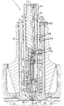
- the fuel supply 1, in particular for an internal combustion engine, comprises a body 2, substantially cylindrical, crossed by a fuel injection pipe 15, substantially parallel to the longitudinal central axis of the body 2, and comprising an inlet lateral 3 of fuel located in the lower half of the body 2, approximately halfway up thereof in the example shown in the appended figure.
- the body 2 successively contains, from bottom to top, an injection needle 4 extended by an elongated pusher 5 comprising a head 6 receiving the support of a spring 7 for closing the prestressed closure using a screw 8.
- the body 2 of the injector 1 is disposed in a sheath 9 housed in the cylinder head 10; the references 12 representing the valves arranged on either side of the injector on their respective seats 13. Different seals 29 are also provided between the cylinder head 10, the sleeve 9 and the body 2 of the injector.
- the injection needle 4 whose conical end 18 rests, in the closed position of the injector, on a conical seat, controls, in a conventional manner, the injection of fuel into the combustion chamber 16 via an injection nozzle 17.
- the pusher is short enough, in the longitudinal direction, so that the level of lateral fuel inlet is located above the upper end of the assembly constituted by the adjusting screw 8, the spring 7, the pusher 5 and the injection needle 4 placed in series.
- the pusher 5 is substantially shorter than the injection needle 4, the length of the pusher representing for example about a quarter of that of the needle. It may further be noted that the length and diameter of the pusher 5 are reduced, respectively, to about one tenth and to about half the length and diameter of a conventional pusher.
- the body 2 of the injector comprises an upper part 20 where the injection conduit 15 is substantially parallel to the longitudinal central axis of the body 2.
- the level of lateral fuel supply is located substantially halfway up the injector body above the adjusting screw 8, and the fuel supply device comprises an inlet pipe 35 connected by a connecting screw 36 to the pipe 15.
- the body 2 of the injector further comprises an intermediate piece 21 surrounding the body 37 of the pusher 5 and a lower part 23 where the injection duct 15 is oblique and opens into an annular groove 24.
- the intermediate piece 21 is pierced with a bore 22 which connects the two parts of the injection pipe located in the upper 20 and lower 23 parts of the body 2 of the injector. The fitting of the intermediate piece 21 is facilitated by a centering pin 27.
- the upper parts 20 and lower lower 23, as well as the intermediate part 21 are joined by a part 26 enveloping the lower part 23, the intermediate part 21 as well as the lower end of the upper part 20, the sealing at the base of this part 26 being ensured by a metal O-ring 28.
- the adjusting screw 8 is coaxially secured to a driven pinion 30 meshing with a driving pinion 31 coaxially secured to a control rod 32, rotatably mounted in the body 2 of the injector 1, and s' extending to the upper end of the injector so as to be operable from the outside.
- a locking pin 33 of the upper end of the control rod 32 is provided.
- an injector of this type is well known and will be briefly indicated below.
- a certain amount of fuel is discharged under pressure into the injection pipe 15 and enters the annular chamber 24.
- the fuel pressure first generates a pushing force on the shoulder 25 of the needle 4 which has the effect of lifting the conical end 18 of the needle 4 from its seat 19.
- a part of the fuel is then expelled by the injection nozzle 17 into the combustion chamber 16.
- the injection continues as long as the fuel pressure exerted on the shoulder 25 is sufficient to overcome the force of the return spring 7. After which, the needle is reapplied on its seat 19 and the injection is stopped until the next cycle.
- the pusher 5 is of reduced length and therefore has a relatively low inert mass makes it possible to improve the injection of fuel, and in particular to avoid disturbances in the rebound of the injection needle on its seat which occur with a relatively heavy pusher of the usual type.
Landscapes
- Engineering & Computer Science (AREA)
- Chemical & Material Sciences (AREA)
- Combustion & Propulsion (AREA)
- Mechanical Engineering (AREA)
- General Engineering & Computer Science (AREA)
- Fuel-Injection Apparatus (AREA)
- Control Of The Air-Fuel Ratio Of Carburetors (AREA)
Applications Claiming Priority (2)
| Application Number | Priority Date | Filing Date | Title |
|---|---|---|---|
| FR8115406A FR2511084B1 (fr) | 1981-08-07 | 1981-08-07 | Injecteur de combustible notamment pour un moteur a combustion interne |
| FR8115406 | 1981-08-07 |
Publications (2)
| Publication Number | Publication Date |
|---|---|
| EP0072269A1 EP0072269A1 (fr) | 1983-02-16 |
| EP0072269B1 true EP0072269B1 (fr) | 1985-10-09 |
Family
ID=9261308
Family Applications (1)
| Application Number | Title | Priority Date | Filing Date |
|---|---|---|---|
| EP82401238A Expired EP0072269B1 (fr) | 1981-08-07 | 1982-07-01 | Injecteur de combustible notamment pour un moteur à combustion interne |
Country Status (16)
| Country | Link |
|---|---|
| US (1) | US4480792A (enExample) |
| EP (1) | EP0072269B1 (enExample) |
| JP (1) | JPS5827879A (enExample) |
| KR (1) | KR880000479B1 (enExample) |
| BR (1) | BR8204049A (enExample) |
| CS (1) | CS241116B2 (enExample) |
| DD (1) | DD202595A5 (enExample) |
| DE (1) | DE3266801D1 (enExample) |
| DK (1) | DK154167C (enExample) |
| ES (1) | ES273654Y (enExample) |
| FI (1) | FI70301C (enExample) |
| FR (1) | FR2511084B1 (enExample) |
| NO (1) | NO154238C (enExample) |
| PL (1) | PL137105B1 (enExample) |
| SU (1) | SU1144623A3 (enExample) |
| YU (1) | YU168782A (enExample) |
Families Citing this family (2)
| Publication number | Priority date | Publication date | Assignee | Title |
|---|---|---|---|---|
| GB8329798D0 (en) * | 1983-11-08 | 1983-12-14 | Lucas Ind Plc | Fuel injection nozzles |
| AU689430B3 (en) * | 1995-07-28 | 1998-03-26 | Dan Maxwell Etherington | Vegetable oil extraction method and equipment |
Citations (2)
| Publication number | Priority date | Publication date | Assignee | Title |
|---|---|---|---|---|
| US3777984A (en) * | 1972-01-20 | 1973-12-11 | Mack Trucks | Miniature fuel injection nozzle and holder assembly |
| GB1557057A (en) * | 1975-12-06 | 1979-12-05 | Bosch Gmbh Robert | Fuel injection nozzels for internal combustion engines |
Family Cites Families (6)
| Publication number | Priority date | Publication date | Assignee | Title |
|---|---|---|---|---|
| GB736446A (en) * | 1953-04-15 | 1955-09-07 | Cav Ltd | Liquid fuel injection nozzle holders for internal combustion engines |
| JPS428884Y1 (enExample) * | 1964-04-08 | 1967-05-12 | ||
| GB1210381A (en) * | 1967-01-13 | 1970-10-28 | Bryce Berger Ltd | Liquid fuel injection nozzle units for internal combustion engines |
| DE2120465C3 (de) * | 1971-04-27 | 1973-10-11 | Maschinenfabrik Augsburg-Nuernberg Ag, 8900 Augsburg | Brennstoffeinspritzventil |
| FR2216455B1 (enExample) * | 1973-02-07 | 1978-03-24 | Bosch Gmbh Robert | |
| JPS526409A (en) * | 1975-07-07 | 1977-01-18 | Hitachi Medical Corp | Electronic scanning type ultrasonic deflection system |
-
1981
- 1981-08-07 FR FR8115406A patent/FR2511084B1/fr not_active Expired
-
1982
- 1982-06-22 US US06/390,928 patent/US4480792A/en not_active Expired - Lifetime
- 1982-06-30 KR KR8202922A patent/KR880000479B1/ko not_active Expired
- 1982-07-01 EP EP82401238A patent/EP0072269B1/fr not_active Expired
- 1982-07-01 DE DE8282401238T patent/DE3266801D1/de not_active Expired
- 1982-07-06 ES ES1982273654U patent/ES273654Y/es not_active Expired
- 1982-07-12 BR BR8204049A patent/BR8204049A/pt unknown
- 1982-07-16 SU SU823463801A patent/SU1144623A3/ru active
- 1982-08-02 DK DK345482A patent/DK154167C/da not_active IP Right Cessation
- 1982-08-02 JP JP57135056A patent/JPS5827879A/ja active Granted
- 1982-08-03 YU YU01687/82A patent/YU168782A/xx unknown
- 1982-08-03 CS CS825798A patent/CS241116B2/cs unknown
- 1982-08-04 PL PL1982237769A patent/PL137105B1/pl unknown
- 1982-08-05 FI FI822721A patent/FI70301C/fi not_active IP Right Cessation
- 1982-08-06 NO NO822692A patent/NO154238C/no unknown
- 1982-08-06 DD DD82242327A patent/DD202595A5/de unknown
Patent Citations (2)
| Publication number | Priority date | Publication date | Assignee | Title |
|---|---|---|---|---|
| US3777984A (en) * | 1972-01-20 | 1973-12-11 | Mack Trucks | Miniature fuel injection nozzle and holder assembly |
| GB1557057A (en) * | 1975-12-06 | 1979-12-05 | Bosch Gmbh Robert | Fuel injection nozzels for internal combustion engines |
Also Published As
| Publication number | Publication date |
|---|---|
| KR880000479B1 (ko) | 1988-04-07 |
| EP0072269A1 (fr) | 1983-02-16 |
| ES273654Y (es) | 1984-11-16 |
| FR2511084A1 (fr) | 1983-02-11 |
| JPH0549815B2 (enExample) | 1993-07-27 |
| DK154167B (da) | 1988-10-17 |
| KR840000736A (ko) | 1984-02-27 |
| US4480792A (en) | 1984-11-06 |
| DE3266801D1 (en) | 1985-11-14 |
| PL237769A1 (en) | 1983-02-28 |
| SU1144623A3 (ru) | 1985-03-07 |
| FI822721A0 (fi) | 1982-08-05 |
| ES273654U (es) | 1984-04-01 |
| CS241116B2 (en) | 1986-03-13 |
| PL137105B1 (en) | 1986-04-30 |
| DD202595A5 (de) | 1983-09-21 |
| CS579882A2 (en) | 1985-07-16 |
| FR2511084B1 (fr) | 1985-10-04 |
| YU168782A (en) | 1988-04-30 |
| FI70301B (fi) | 1986-02-28 |
| NO154238C (no) | 1986-08-13 |
| FI822721L (fi) | 1983-02-08 |
| FI70301C (fi) | 1986-09-15 |
| BR8204049A (pt) | 1983-07-05 |
| JPS5827879A (ja) | 1983-02-18 |
| DK154167C (da) | 1989-03-20 |
| NO822692L (no) | 1983-02-08 |
| NO154238B (no) | 1986-05-05 |
| DK345482A (da) | 1983-02-08 |
Similar Documents
| Publication | Publication Date | Title |
|---|---|---|
| EP0119894B1 (fr) | Perfectionnement aux systèmes d'injection à commande électromagnétique pour moteur Diesel de type pression-temps où l'aiguille de l'injecteur est pilotée par la décharge puis la charge d'une capacité | |
| EP0713036B1 (fr) | Clapet d'électrovanne et circuit de recyclage de vapeurs d'essence de moteur à combustion interne | |
| FR2759740A1 (fr) | Dispositif d'injection a accumulateur pour moteurs a combustion interne multicylindriques | |
| EP2964933A1 (fr) | Dispositif de dosage compact pour injecteur a deux circuits de carburant pour une turbomachine d'aeronef | |
| FR2574129A1 (fr) | Valve electromagnetique pour systeme d'injection de carburant | |
| FR2759741A1 (fr) | Dispositif d'injection a conduite collective pour un moteur a combustion interne multicylindrique, avec injecteurs de carburant commandes par electrovalve | |
| EP0291386B1 (fr) | Injecteur pour moteur à allumage commandé et injection directe | |
| FR2462573A1 (fr) | Injecteur a teton d'etranglement | |
| FR2652426A1 (fr) | Detendeur de bouteille de gaz. | |
| EP1312864B1 (fr) | Dispositif doseur de combustible pour injecteur de turbomachine | |
| EP0072269B1 (fr) | Injecteur de combustible notamment pour un moteur à combustion interne | |
| FR2783514A3 (fr) | Unite hydraulique de levage rapide utilisee dans un verin | |
| FR2772430A1 (fr) | Injecteur de carburant pour un moteur a combustion interne | |
| FR2797917A1 (fr) | Dispositif d'injection pour moteur a combustion interne a injection directe | |
| FR2727158A1 (fr) | Vanne de controle de la quantite de gaz d'echappement recyclee dans un moteur a combustion interne | |
| FR2792371A1 (fr) | Valve de commande pour dispositif d'injection, comprenant un piston et des butees pour celui-ci | |
| FR2554511A1 (fr) | Injecteur de carburant | |
| FR2811379A1 (fr) | Injecteur de craburant avec un element de commande de pression | |
| FR2797914A1 (fr) | Soupape de commande d'injecteur de carburant | |
| FR2468775A1 (fr) | Distributeur hydraulique | |
| FR2530292A1 (fr) | Clapet d'alimentation | |
| EP2005047B1 (fr) | Electrovanne de regulation de pression | |
| FR2654469A1 (fr) | Injecteur de carburant pour moteur a combustion interne, permettant un jet de carburant en forme de parapluie. | |
| FR2528914A1 (fr) | Injecteur de combustible pour moteur a combustion interne | |
| FR2514417A1 (fr) | Commande d'admission pour moteur a combustion interne suralimente equipe de pompes d'injection disposees individuellement |
Legal Events
| Date | Code | Title | Description |
|---|---|---|---|
| PUAI | Public reference made under article 153(3) epc to a published international application that has entered the european phase |
Free format text: ORIGINAL CODE: 0009012 |
|
| AK | Designated contracting states |
Designated state(s): BE CH DE GB IT LI NL SE |
|
| 17P | Request for examination filed |
Effective date: 19830610 |
|
| ITF | It: translation for a ep patent filed | ||
| GRAA | (expected) grant |
Free format text: ORIGINAL CODE: 0009210 |
|
| AK | Designated contracting states |
Designated state(s): BE CH DE GB IT LI NL SE |
|
| REF | Corresponds to: |
Ref document number: 3266801 Country of ref document: DE Date of ref document: 19851114 |
|
| PLBE | No opposition filed within time limit |
Free format text: ORIGINAL CODE: 0009261 |
|
| STAA | Information on the status of an ep patent application or granted ep patent |
Free format text: STATUS: NO OPPOSITION FILED WITHIN TIME LIMIT |
|
| 26N | No opposition filed | ||
| PGFP | Annual fee paid to national office [announced via postgrant information from national office to epo] |
Ref country code: NL Payment date: 19870731 Year of fee payment: 6 |
|
| PG25 | Lapsed in a contracting state [announced via postgrant information from national office to epo] |
Ref country code: GB Effective date: 19890701 |
|
| PG25 | Lapsed in a contracting state [announced via postgrant information from national office to epo] |
Ref country code: LI Effective date: 19890731 Ref country code: CH Effective date: 19890731 Ref country code: BE Effective date: 19890731 |
|
| BERE | Be: lapsed |
Owner name: SOC. D'ETUDES DE MACHINES THERMIQUES SEMT Effective date: 19890731 |
|
| PG25 | Lapsed in a contracting state [announced via postgrant information from national office to epo] |
Ref country code: NL Effective date: 19900201 |
|
| GBPC | Gb: european patent ceased through non-payment of renewal fee | ||
| NLV4 | Nl: lapsed or anulled due to non-payment of the annual fee | ||
| REG | Reference to a national code |
Ref country code: CH Ref legal event code: PL |
|
| PG25 | Lapsed in a contracting state [announced via postgrant information from national office to epo] |
Ref country code: DE Effective date: 19900403 |
|
| EAL | Se: european patent in force in sweden |
Ref document number: 82401238.9 |
|
| PGFP | Annual fee paid to national office [announced via postgrant information from national office to epo] |
Ref country code: SE Payment date: 19970716 Year of fee payment: 16 |
|
| PG25 | Lapsed in a contracting state [announced via postgrant information from national office to epo] |
Ref country code: SE Free format text: LAPSE BECAUSE OF NON-PAYMENT OF DUE FEES Effective date: 19980702 |
|
| EUG | Se: european patent has lapsed |
Ref document number: 82401238.9 |