EP0713036B1 - Clapet d'électrovanne et circuit de recyclage de vapeurs d'essence de moteur à combustion interne - Google Patents
Clapet d'électrovanne et circuit de recyclage de vapeurs d'essence de moteur à combustion interne Download PDFInfo
- Publication number
- EP0713036B1 EP0713036B1 EP95402505A EP95402505A EP0713036B1 EP 0713036 B1 EP0713036 B1 EP 0713036B1 EP 95402505 A EP95402505 A EP 95402505A EP 95402505 A EP95402505 A EP 95402505A EP 0713036 B1 EP0713036 B1 EP 0713036B1
- Authority
- EP
- European Patent Office
- Prior art keywords
- seat
- solenoid valve
- valve flap
- intermediate member
- free end
- Prior art date
- Legal status (The legal status is an assumption and is not a legal conclusion. Google has not performed a legal analysis and makes no representation as to the accuracy of the status listed.)
- Expired - Lifetime
Links
Images

Classifications
-
- F—MECHANICAL ENGINEERING; LIGHTING; HEATING; WEAPONS; BLASTING
- F02—COMBUSTION ENGINES; HOT-GAS OR COMBUSTION-PRODUCT ENGINE PLANTS
- F02M—SUPPLYING COMBUSTION ENGINES IN GENERAL WITH COMBUSTIBLE MIXTURES OR CONSTITUENTS THEREOF
- F02M25/00—Engine-pertinent apparatus for adding non-fuel substances or small quantities of secondary fuel to combustion-air, main fuel or fuel-air mixture
- F02M25/08—Engine-pertinent apparatus for adding non-fuel substances or small quantities of secondary fuel to combustion-air, main fuel or fuel-air mixture adding fuel vapours drawn from engine fuel reservoir
- F02M25/0836—Arrangement of valves controlling the admission of fuel vapour to an engine, e.g. valve being disposed between fuel tank or absorption canister and intake manifold
-
- F—MECHANICAL ENGINEERING; LIGHTING; HEATING; WEAPONS; BLASTING
- F16—ENGINEERING ELEMENTS AND UNITS; GENERAL MEASURES FOR PRODUCING AND MAINTAINING EFFECTIVE FUNCTIONING OF MACHINES OR INSTALLATIONS; THERMAL INSULATION IN GENERAL
- F16K—VALVES; TAPS; COCKS; ACTUATING-FLOATS; DEVICES FOR VENTING OR AERATING
- F16K1/00—Lift valves or globe valves, i.e. cut-off apparatus with closure members having at least a component of their opening and closing motion perpendicular to the closing faces
- F16K1/32—Details
- F16K1/34—Cutting-off parts, e.g. valve members, seats
- F16K1/44—Details of seats or valve members of double-seat valves
-
- Y—GENERAL TAGGING OF NEW TECHNOLOGICAL DEVELOPMENTS; GENERAL TAGGING OF CROSS-SECTIONAL TECHNOLOGIES SPANNING OVER SEVERAL SECTIONS OF THE IPC; TECHNICAL SUBJECTS COVERED BY FORMER USPC CROSS-REFERENCE ART COLLECTIONS [XRACs] AND DIGESTS
- Y10—TECHNICAL SUBJECTS COVERED BY FORMER USPC
- Y10T—TECHNICAL SUBJECTS COVERED BY FORMER US CLASSIFICATION
- Y10T137/00—Fluid handling
- Y10T137/8593—Systems
- Y10T137/86928—Sequentially progressive opening or closing of plural valves
- Y10T137/86936—Pressure equalizing or auxiliary shunt flow
- Y10T137/86944—One valve seats against other valve [e.g., concentric valves]
Definitions
- the present invention relates to a solenoid valve and a combustion engine petrol vapor recycling system internal. More particularly, it relates to a solenoid valve comprising a seat and an electromagnet coil, said valve comprising the free end of a movable core inside the hub of said coil.
- the solenoid coil is generally supplied with chopped current of constant period and variable duty cycle, the duty cycle being defined as the report of the duration during which, during a period, the tension is at a high level, for the duration of the period.
- the end free of the movable core forms a valve whose position varies in function of the vacuum downstream of the solenoid valve and of the ratio cyclic opening, between a closed position where this free end is supported on the seat and therefore closes the solenoid valve, and a position furthest from the seat where the flow is maximum.
- the flow is a function of both the distance between the valve and the seat as well as the vacuum prevailing between the interior and exterior of the solenoid valve.
- This solenoid valve comprises an intermediate member forming a double valve.
- the assembly formed by the shutter member of the low flow valve and the intermediate member is pressed in the direction of the valve seat high flow by elastic means acting against the action of the solenoid of the solenoid valve. No specific means are however provided for the control of the intermediate member.
- the present invention aims to overcome these drawbacks. More in particular, the invention aims to provide a solenoid valve which has a significant flow rate for small differences in pressure and which, for larger pressure differences, has a lower flow and a flow / pressure characteristic conventional solenoid valve.
- the invention firstly relates to a valve solenoid valve according to claim 1.
- said intermediate member is cup-shaped, said second seat being formed in the bottom of said cup, said bottom being, on the side from its outer face, facing said first seat, and said free end of the core being engaged inside said cup.
- said elastic means comprise a helical spring in support, at a of its ends on a bearing surface of the housing, and at its other end on a shoulder of said intermediate member.
- Said free end of the movable core and said second seat can be tapered.
- Second elastic means can also be arranged to press said movable core towards said second seat.
- the present invention also relates to a circuit for recycling of internal combustion engine gasoline vapors, characterized in that it comprises a solenoid valve having a valve as described above.
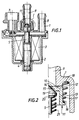
- the solenoid valve of Figures 1 and 2 has a body 1 and a cover 2 delimiting a space in which is housed an electromagnet coil 3. Inside the coil hub is a fixed magnetic core 4 and a movable core 5 axially distant of a variable length defining the air gap of the coil. The smaller the air gap, the stronger for a duty cycle of the given coil, the force of attraction of the movable core 5 by the fixed core 4.
- Coil 3 is supplied with chopped current at duty cycle variable from a connector 7 formed in the housing 1.
- the housing 1 also forms an inlet conduit 8 and a conduit fluid outlet 9 for the interior space of the housing.
- the inner end of the conduit 9 defines a first seat 10 with which a member cooperates intermediate 11.
- This member 11 is cup-shaped with a bottom 12 and a wall substantially cylindrical lateral 13.
- the face of the bottom 12 external to the cup is facing the seat 10.
- the bottom 12 further includes a orifice 14 of which the part situated on the interior side of the cup is chamfered so as to form a second seat 15, conical, coaxial with first seat, and whose opening section is smaller than that of the first seat 10.
- a shoulder 16 of the wall 13 receives one end of a spring helical (here frustoconical) 17 whose other end is supported in a groove 18 formed in the housing 1.
- the spring 17 therefore pushes the member 10 to away from seat 10.
- the movable core 5 is formed by a cylindrical rod, one end of which is engaged in the hub of the coil, and the other end of which is in cone shape 19 and is engaged inside the member 13 to cooperate with seat 15 of the latter.
- a shoulder 20 receives one end of a other spring 21, the other end of which bears on the housing so to tend to apply the conical end of the core 5 on the second seat 15.
- the seat 10 is therefore open, allowing a high flow rate.
- This diet is that of part A of the curve of figure 3 where the flow rate increases very quickly with depression.
- FIG. 4 shows a fuel tank 30 for a motor internal combustion, and in particular for a motor vehicle engine.
- the tank 30 has a filling opening 31 and another opening from which a line 32 leaves, the other end of which is connected to a trap for gasoline vapors 33 with activated carbon.
- the output of trap 33 is connected to the inlet of a solenoid valve 34 of the type which has just been described. This solenoid valve 34 is controlled by a computer 35.
- the outlet of the solenoid valve 34 is connected to the inlet of a valve butterfly 36, to which the air and petrol also arrive and the outlet of which is connected in a known manner to the ramp 37 supplying the injectors of the engine.
- the computer 35 controls, as a function of the speed of rotation of the motor, the duty cycle of the chopped current supplying the coil 7 and thus controls the flow of gasoline vapors into the solenoid valve 34.
- This solenoid valve is closed at rest, i.e. when the engine is at rest. It opens gradually by increasing the duty cycle to the extent that the computer requests it.
- valve according to the invention the recycling of petrol vapors is performed properly, including at high speed, when depression motor is weak, while keeping good accuracy on low flow diet.
Landscapes
- Engineering & Computer Science (AREA)
- General Engineering & Computer Science (AREA)
- Mechanical Engineering (AREA)
- Chemical & Material Sciences (AREA)
- Combustion & Propulsion (AREA)
- Magnetically Actuated Valves (AREA)
- Supplying Secondary Fuel Or The Like To Fuel, Air Or Fuel-Air Mixtures (AREA)
Description
- la figure 1 est vue en coupe axiale d'une électrovanne comportant un clapet selon l'invention;
- la figure 2 est une demi-vue à plus grande échelle du détail l de la figure 1;
- la figure 3 illustre la caractéristique de fonctionnement de la vanne de la figure 1; et
- la figure 4 représente schématiquement un circuit de recyclage de vapeurs d'essence comportant le clapet de la figure 1.
Claims (6)
- Clapet d'électrovanne comportant un premier siège (10), une bobine (3) d'électroaimant, ledit clapet comprenant l'extrémité libre (19) d'un noyau mobile (5) à l'intérieur du moyeu de ladite bobine, et un organe intermédiaire (11) susceptible de venir en appui sur ledit premier siège et comportant lui-même un deuxième siège (15) en vis-à-vis du premier siège et de section plus faible que celle du premier siège, ladite extrémité libre du noyau mobile étant susceptible de venir en appui sur ledit deuxième siège, caractérisé par le fait qu'il comprend en outre des moyens élastiques (17) pour presser ledit organe intermédiaire à l'écart dudit premier siège pour des valeurs de dépression dans l'électrovanne inférieures à une valeur prédéterminée (P0), ledit organe intermédiaire (11) étant plaqué contre ledit premier siège (10) contre l'action desdits moyens élastiques (17) pour des valeurs de dépression dans l'électrovanne supérieures à ladite valeur prédéterminée.
- Clapet d'électrovanne selon la revendication 1, dans lequel ledit organe intermédiaire (11) est en forme de coupelle, ledit deuxième siège (15) étant formé dans le fond (12) de ladite coupelle, ledit fond étant, du côté de sa face extérieure, en vis-à-vis dudit premier siège (10), et ladite extrémité libre du noyau étant engagée à l'intérieur de ladite coupelle.
- Clapet d'électrovanne selon l'une quelconque des revendications 1 et 2, dans lequel lesdits moyens élastiques (17) comprennent un ressort hélicoïdal en appui, à une de ses extrémités sur une surface d'appui (18) du boítier, et à son autre extrémité sur un épaulement (16) dudit organe intermédiaire (11).
- Clapet d'électrovanne selon l'une quelconque des revendications 1 à 3, dans lequel ladite extrémité libre (19) du noyau mobile et ledit deuxième siège (15) sont coniques.
- Clapet d'électrovanne selon l'une quelconque des revendications 1 à 4, dans lequel des deuxièmes moyens élastiques (21) sont agencés pour presser ledit noyau mobile en direction dudit deuxième siège (15).
- Circuit de recyclage de vapeurs d'essence de moteur à combustion interne, caractérisé par le fait qu'il comprend une électrovanne possédant un clapet selon l'une quelconque des revendications 1 à 5.
Applications Claiming Priority (2)
| Application Number | Priority Date | Filing Date | Title |
|---|---|---|---|
| FR9413758 | 1994-11-17 | ||
| FR9413758A FR2727185A1 (fr) | 1994-11-17 | 1994-11-17 | Clapet d'electrovanne et circuit de recyclage de vapeurs d'essence de moteur a combustion interne |
Publications (2)
| Publication Number | Publication Date |
|---|---|
| EP0713036A1 EP0713036A1 (fr) | 1996-05-22 |
| EP0713036B1 true EP0713036B1 (fr) | 2002-01-09 |
Family
ID=9468877
Family Applications (1)
| Application Number | Title | Priority Date | Filing Date |
|---|---|---|---|
| EP95402505A Expired - Lifetime EP0713036B1 (fr) | 1994-11-17 | 1995-11-09 | Clapet d'électrovanne et circuit de recyclage de vapeurs d'essence de moteur à combustion interne |
Country Status (5)
| Country | Link |
|---|---|
| US (1) | US5657962A (fr) |
| EP (1) | EP0713036B1 (fr) |
| JP (1) | JPH08210548A (fr) |
| DE (1) | DE69524929T2 (fr) |
| FR (1) | FR2727185A1 (fr) |
Families Citing this family (28)
| Publication number | Priority date | Publication date | Assignee | Title |
|---|---|---|---|---|
| DE19529724A1 (de) * | 1995-08-12 | 1997-02-13 | Teves Gmbh Alfred | Elektromagnetventil, insbesondere für hydraulische Kraftfahrzeugbremsanlagen mit Radschlupfregelung |
| US6050245A (en) * | 1997-02-12 | 2000-04-18 | Siemens Canada Limited | Canister vent valve having at least one sensor and single electric actuator operatively connected to a single electrical connector |
| US5970958A (en) * | 1997-10-10 | 1999-10-26 | Eaton Corporation | Fuel vapor purge control |
| DE19836493B4 (de) * | 1998-03-31 | 2008-07-24 | Continental Teves Ag & Co. Ohg | Elektromagnetventil |
| US6309541B1 (en) | 1999-10-29 | 2001-10-30 | Ontogen Corporation | Apparatus and method for multiple channel high throughput purification |
| US6548837B1 (en) * | 1999-06-08 | 2003-04-15 | Johnson Controls Automotive Electronics | Solenoid bleed valve for a device for the disposal of vapours |
| US6394073B1 (en) | 1999-08-26 | 2002-05-28 | Caterpillar Inc. | Hydraulic valve with hydraulically assisted opening and fuel injector using same |
| US6358414B1 (en) | 1999-10-29 | 2002-03-19 | Ontogen Corporation | Pressure regulation apparatus and method for multiple channel high throughput purification |
| US6843271B2 (en) * | 2000-08-08 | 2005-01-18 | Siemens Vdo Automotive, Inc. | Fuel tank pressure control valve including an integrated sensor |
| US6668807B2 (en) * | 2000-08-08 | 2003-12-30 | Siemens Automotive Inc. | Evaporative emission control system including a fuel tank isolation valve |
| WO2002025556A1 (fr) * | 2000-09-21 | 2002-03-28 | Digital Network Shopping, Llc | Procede et appareil permettant d'effectuer des achats par voie numerique |
| JP2002181221A (ja) * | 2000-12-11 | 2002-06-26 | Smc Corp | 流量制御弁 |
| DE10229789A1 (de) * | 2002-02-02 | 2003-08-14 | Continental Teves Ag & Co Ohg | Elektromagnetventil |
| US6745794B2 (en) * | 2002-06-07 | 2004-06-08 | Praxair Technology, Inc. | Flow control valve |
| KR100721377B1 (ko) * | 2003-02-07 | 2007-05-23 | 주식회사 만도 | 브레이크시스템용 솔레노이드밸브 |
| US9316130B1 (en) | 2007-03-07 | 2016-04-19 | Thermal Power Recovery Llc | High efficiency steam engine, steam expander and improved valves therefor |
| US8448440B2 (en) * | 2007-03-07 | 2013-05-28 | Thermal Power Recovery Llc | Method and apparatus for achieving higher thermal efficiency in a steam engine or steam expander |
| USD706389S1 (en) | 2010-03-30 | 2014-06-03 | Eaton Corporation | Fuel tank isolation valve |
| US9371803B2 (en) | 2009-04-22 | 2016-06-21 | Eaton Corporation | Valve assembly |
| US8573255B2 (en) | 2009-04-22 | 2013-11-05 | Eaton Corporation | Valve assembly for high-pressure fluid reservoir |
| USD829304S1 (en) | 2010-03-30 | 2018-09-25 | Eaton Intelligent Power Limited | Valve carriage |
| US9500291B2 (en) | 2010-03-30 | 2016-11-22 | Eaton Corporation | Isolation valve with fast depressurization for high-pressure fuel tank |
| USD706390S1 (en) | 2010-03-30 | 2014-06-03 | Eaton Corporation | Fuel tank isolation valve |
| US8944100B2 (en) * | 2010-03-30 | 2015-02-03 | Eaton Corporation | Isolation valve with fast depressurization for high-pressure fuel tank |
| ITBO20110563A1 (it) * | 2011-10-03 | 2013-04-04 | Magneti Marelli Spa | Valvola canister con forza di attuazione ridotta |
| JP6253623B2 (ja) * | 2015-09-14 | 2017-12-27 | 本田技研工業株式会社 | 燃料遮断弁 |
| DE102017122253A1 (de) * | 2017-09-26 | 2019-03-28 | Eagle Actuator Components Gmbh & Co. Kg | Aktiv und passiv betätigbares Ventil |
| CN113280519B (zh) * | 2021-05-27 | 2022-12-23 | 深圳嘉普通太阳能股份有限公司 | 一种家用太阳能热水器 |
Family Cites Families (16)
| Publication number | Priority date | Publication date | Assignee | Title |
|---|---|---|---|---|
| US2866477A (en) * | 1954-03-19 | 1958-12-30 | Crane Co | Combined throttle and stop valve |
| US2983286A (en) * | 1959-01-19 | 1961-05-09 | Ranco Inc | Reversing valve |
| FR2425617A1 (fr) * | 1978-05-08 | 1979-12-07 | Saunier Duval | Dispositif de reglage du petit debit d'une electrovanne pour appareils du genre chaudiere a gaz |
| FR2437554A1 (fr) * | 1978-09-26 | 1980-04-25 | Saunier Duval | Systeme de reglage d'un ressort de clapet pour electrovalve a gaz |
| JPS579380A (en) * | 1980-06-20 | 1982-01-18 | Hitachi Ltd | Proportional control valve |
| JPS5770727A (en) * | 1980-10-22 | 1982-05-01 | Hitachi Ltd | Pressure control valve unit |
| FR2598992B1 (fr) * | 1986-05-26 | 1992-04-03 | Jidosha Kiki Co | Servofrein pour vehicule |
| US4944276A (en) * | 1987-10-06 | 1990-07-31 | Colt Industries Inc | Purge valve for on board fuel vapor recovery systems |
| GB8727297D0 (en) * | 1987-11-20 | 1987-12-23 | Lucas Ind Plc | Solenoid valve |
| JPH01174683U (fr) * | 1988-05-31 | 1989-12-12 | ||
| US5174262A (en) * | 1989-04-14 | 1992-12-29 | Brunswick Corporation | Control valve for fuel injection |
| SE467223B (sv) * | 1990-11-19 | 1992-06-15 | Tour & Andersson Ab | Ventil foer tvaa- eller flervaegs floedesreglering |
| JPH0560259A (ja) * | 1991-08-28 | 1993-03-09 | Mitsubishi Electric Corp | 流量制御バルブ |
| DE4229105C1 (fr) * | 1992-09-01 | 1993-09-09 | Fa. Carl Freudenberg, 69469 Weinheim, De | |
| DE4329396A1 (de) * | 1993-09-01 | 1995-03-02 | Pierburg Gmbh | Elektropneumatisches Steuerventil |
| US5509395A (en) * | 1995-03-31 | 1996-04-23 | Siemens Electric Limited | Canister purge flow regulator |
-
1994
- 1994-11-17 FR FR9413758A patent/FR2727185A1/fr active Granted
-
1995
- 1995-11-09 DE DE69524929T patent/DE69524929T2/de not_active Expired - Fee Related
- 1995-11-09 EP EP95402505A patent/EP0713036B1/fr not_active Expired - Lifetime
- 1995-11-17 US US08/559,909 patent/US5657962A/en not_active Expired - Fee Related
- 1995-11-17 JP JP7299619A patent/JPH08210548A/ja active Pending
Also Published As
| Publication number | Publication date |
|---|---|
| DE69524929T2 (de) | 2002-08-22 |
| FR2727185B1 (fr) | 1997-02-14 |
| EP0713036A1 (fr) | 1996-05-22 |
| FR2727185A1 (fr) | 1996-05-24 |
| DE69524929D1 (de) | 2002-02-14 |
| US5657962A (en) | 1997-08-19 |
| JPH08210548A (ja) | 1996-08-20 |
Similar Documents
| Publication | Publication Date | Title |
|---|---|---|
| EP0713036B1 (fr) | Clapet d'électrovanne et circuit de recyclage de vapeurs d'essence de moteur à combustion interne | |
| EP0119894B1 (fr) | Perfectionnement aux systèmes d'injection à commande électromagnétique pour moteur Diesel de type pression-temps où l'aiguille de l'injecteur est pilotée par la décharge puis la charge d'une capacité | |
| FR2716936A1 (fr) | Circuit de distribution de carburant pour moteur à combustion interne. | |
| FR2738294A1 (fr) | Injecteur pour moteur a combustion interne | |
| FR2528913A1 (fr) | Injecteur de carburant | |
| WO1999031372A1 (fr) | Vanne de controle pour systeme de recirculation des gaz d'echappement d'un moteur a combustion interne | |
| FR2463294A1 (fr) | Electro-injection de precision pour moteurs a combustion interne | |
| EP0631075A1 (fr) | Electrovanne à double siège, et circuit de recyclage de vapeurs d'essence comportant un tel clapet | |
| EP0712998A1 (fr) | Vanne de coupure pour circuit d'injection d'air à l'échappement de moteur à combustion interne | |
| FR2722541A1 (fr) | Injecteur de carburant "bi-jet" a aassistance pneumatique de pulverisation, pour moteur a combustioninterne alimente par injection | |
| EP1312864A1 (fr) | Dispositif doseur de combustible pour injecteur de turbomachine | |
| FR2797310A1 (fr) | Clapet de regulation de pression pour un module d'alimentation en carburant | |
| EP0006770B1 (fr) | Electrovanne, notamment pour carburateur | |
| FR2727158A1 (fr) | Vanne de controle de la quantite de gaz d'echappement recyclee dans un moteur a combustion interne | |
| FR2792371A1 (fr) | Valve de commande pour dispositif d'injection, comprenant un piston et des butees pour celui-ci | |
| FR2797914A1 (fr) | Soupape de commande d'injecteur de carburant | |
| EP1525385B1 (fr) | Injecteur pour carburant gazeux | |
| FR2872245A1 (fr) | Electrovanne munie d'un moyen de guidage du ressort | |
| FR2568317A1 (fr) | Dispositif d'injection de combustible | |
| EP0914557B1 (fr) | Electrovanne par exemple d'impact pour un systeme d'injection de carburant par effet de coup de belier dans un moteur de vehicule | |
| FR2790301A1 (fr) | Soupape a section de passage variable | |
| EP0072269B1 (fr) | Injecteur de combustible notamment pour un moteur à combustion interne | |
| FR2778784A1 (fr) | Procede de commande d'une electrovanne, notamment d'un circuit de purge canister d'un moteur | |
| WO2017194625A1 (fr) | Injecteur de carburant pour moteur à combustion interne | |
| FR2714114A1 (fr) | Dispositif d'admission en air comburant pour moteur à combustion interne. |
Legal Events
| Date | Code | Title | Description |
|---|---|---|---|
| PUAI | Public reference made under article 153(3) epc to a published international application that has entered the european phase |
Free format text: ORIGINAL CODE: 0009012 |
|
| AK | Designated contracting states |
Kind code of ref document: A1 Designated state(s): DE GB IT |
|
| 17P | Request for examination filed |
Effective date: 19961025 |
|
| 17Q | First examination report despatched |
Effective date: 19990708 |
|
| GRAG | Despatch of communication of intention to grant |
Free format text: ORIGINAL CODE: EPIDOS AGRA |
|
| GRAG | Despatch of communication of intention to grant |
Free format text: ORIGINAL CODE: EPIDOS AGRA |
|
| GRAH | Despatch of communication of intention to grant a patent |
Free format text: ORIGINAL CODE: EPIDOS IGRA |
|
| GRAH | Despatch of communication of intention to grant a patent |
Free format text: ORIGINAL CODE: EPIDOS IGRA |
|
| GRAA | (expected) grant |
Free format text: ORIGINAL CODE: 0009210 |
|
| REG | Reference to a national code |
Ref country code: GB Ref legal event code: IF02 |
|
| AK | Designated contracting states |
Kind code of ref document: B1 Designated state(s): DE GB IT |
|
| PG25 | Lapsed in a contracting state [announced via postgrant information from national office to epo] |
Ref country code: IT Free format text: LAPSE BECAUSE OF FAILURE TO SUBMIT A TRANSLATION OF THE DESCRIPTION OR TO PAY THE FEE WITHIN THE PRE;WARNING: LAPSES OF ITALIAN PATENTS WITH EFFECTIVE DATE BEFORE 2007 MAY HAVE OCCURRED AT ANY TIME BEFORE 2007. THE CORRECT EFFECTIVE DATE MAY BE DIFFERENT FROM THE ONE RECORDED.SCRIBED TIME-LIMIT Effective date: 20020109 |
|
| REF | Corresponds to: |
Ref document number: 69524929 Country of ref document: DE Date of ref document: 20020214 |
|
| GBT | Gb: translation of ep patent filed (gb section 77(6)(a)/1977) |
Effective date: 20020417 |
|
| PG25 | Lapsed in a contracting state [announced via postgrant information from national office to epo] |
Ref country code: GB Free format text: LAPSE BECAUSE OF NON-PAYMENT OF DUE FEES Effective date: 20021109 |
|
| PLBE | No opposition filed within time limit |
Free format text: ORIGINAL CODE: 0009261 |
|
| STAA | Information on the status of an ep patent application or granted ep patent |
Free format text: STATUS: NO OPPOSITION FILED WITHIN TIME LIMIT |
|
| 26N | No opposition filed | ||
| PG25 | Lapsed in a contracting state [announced via postgrant information from national office to epo] |
Ref country code: DE Free format text: LAPSE BECAUSE OF NON-PAYMENT OF DUE FEES Effective date: 20030603 |
|
| GBPC | Gb: european patent ceased through non-payment of renewal fee |