EP0072084A2 - Vorrichtung und Verfahren zum exakten Steuern eines automatischen Getriebes mit Überbrückungskupplung - Google Patents
Vorrichtung und Verfahren zum exakten Steuern eines automatischen Getriebes mit Überbrückungskupplung Download PDFInfo
- Publication number
- EP0072084A2 EP0072084A2 EP82301772A EP82301772A EP0072084A2 EP 0072084 A2 EP0072084 A2 EP 0072084A2 EP 82301772 A EP82301772 A EP 82301772A EP 82301772 A EP82301772 A EP 82301772A EP 0072084 A2 EP0072084 A2 EP 0072084A2
- Authority
- EP
- European Patent Office
- Prior art keywords
- speed stage
- lock
- clutch
- hydraulic fluid
- fluid pressure
- Prior art date
- Legal status (The legal status is an assumption and is not a legal conclusion. Google has not performed a legal analysis and makes no representation as to the accuracy of the status listed.)
- Granted
Links
Images


Classifications
-
- F—MECHANICAL ENGINEERING; LIGHTING; HEATING; WEAPONS; BLASTING
- F16—ENGINEERING ELEMENTS AND UNITS; GENERAL MEASURES FOR PRODUCING AND MAINTAINING EFFECTIVE FUNCTIONING OF MACHINES OR INSTALLATIONS; THERMAL INSULATION IN GENERAL
- F16H—GEARING
- F16H61/00—Control functions within control units of change-speed- or reversing-gearings for conveying rotary motion ; Control of exclusively fluid gearing, friction gearing, gearings with endless flexible members or other particular types of gearing
- F16H61/14—Control of torque converter lock-up clutches
- F16H61/143—Control of torque converter lock-up clutches using electric control means
Definitions
- the present invention relates to an accurate control device for a transmission for an automotive vehicle and to a method practiced by said device, and, more particularly, relates to a control device, incorporating an electrically actuated hydraulic fluid pressure control system and an electronic control computer which controls said electrically actuated hydraulic fluid pressure control system, said control device accurately controlling selective supply of hydraulic fluid pressures to a hydraulically controlled transmission so as to accurately set it to any one of its various speed stages, and to a control method for said hydraulically controlled transmission practiced by said device.
- Automatic transmissions for automotive vehicles which include gear transmission mechanisms including several fluid pressure activated friction engaging mechanisms such as multi plate clutches and multi plate brakes are well known in various forms.
- Such an automatic transmissions is usually conventionally controlled by a hydraulic fluid pressure control system, which selectively controls supply of hydraulic fluid pressure to the friction engaging mechanisms, according to decisions that said hydraulic fluid pressure control system makes as to what speed stage of the gear transmission mechanism should be currently engaged, in view of and based upon the current values of various operational parameters of the vehicle, such as the road speed of the vehicle, the load upon an internal combustion engine of the vehicle, and the like.
- Such a conventional hydraulic fluid pressure control system in order to decide upon a speed stage of the gear transmission mechanism which is to be engaged, evaluates various relations between the magnitudes of the throttle hydraulic fluid pressure and the governor hydraulic fluid pressure, by supplying these pressures to various shift valves so as to act upon the valve elements thereof in opposition, according to various equilibrium relationships, and, based upon the movement of these valve elements, supplies of activating fluid pressures to the various friction engaging mechanisms such as the aforementioned clutches and brakes are made, in order to engage the appropriate speed stage which has thus been decided upon.
- the switching controls of these transmission switching valves are performed by electrically actuated means, such as solenoid valve devices or the like, based upon control judgements made by an electronic circuit, instead of according to the above described type of set of equilibrium relations between throttle hydraulic fluid pressure and governor hydraulic fluid pressure, etc., as in conventional hydraulic fluid pressure transmission control systems.
- electrically actuated means such as solenoid valve devices or the like
- an electronic circuit instead of according to the above described type of set of equilibrium relations between throttle hydraulic fluid pressure and governor hydraulic fluid pressure, etc., as in conventional hydraulic fluid pressure transmission control systems.
- an automatic transmission conventionally includes a fluid torque converter, which provides a fluid coupling between the engine of the vehicle and the gear transmission mechanism, thus eliminating the need for any clutch' system for the drive train of the vehicle, allowing smooth shifting of the transmission between its various speed stages while said transmission is transmitting rotational power while the vehicle is moving, and also allowing for the vehicle to be stationary while the engine is turning at a low rotational speed at or close to the idling speed without the engine stalling, as well as providing torque multiplication by fluid flow in a per se well known way when the vehicle is being accelerated at relatively low speed and relatively low engine rotational speed.
- Many such torque converters are of course presently well known.
- such a torque converter comprises: a housing of a generally toroidal shape, on the inside of which there are formed a series of vanes which constitute a pump impeller, and fixed to a power input shaft; a turbine member mounted within the housing as fixed to a power output shaft; and a stator member mounted within the housing via a one way brake on a fixed member.
- the housing of such a torque converter is kept filled with hydraulic fluid, which is pumped thereinto and is also drained therefrom, and in a per se well known way the pump impeller, the stator member, and the turbine member cooperate, when the housing of the torque converter is thus filled with hydraulic fluid, to define a toroidal hydraulic fluid flow circulation system, circulation of hydraulic fluid around which in the general circulation fashion of a smoke ring is arranged to transfer torque in a conventional manner between the pump impeller and the turbine member of the torque converter.
- This supply of hydraulic fluid for filling the torque converter is typically provided to the inside of the housing thereof via a first channel defined along or beside the central rotational axis thereof - in more detail, via a hole in one of the shafts passing along said central rotational axis or through a space defined between two concentric ones of such shafts; and the draining of hydraulic fluid from the torque converter is also typically performed in a similar manner, through a second such channel.
- the supply of hydraulic fluid is provided, generally in the prior art, from a torque converter hydraulic fluid pressure regulation valve which supplies a supply of hydraulic fluid at a regulated torque converter hydraulic fluid pressure, which is generally rather lower than the line hydraulic fluid pressure, to the torque converter.
- a torque converter it has become more and more common nowadays for a torque converter to be provided with a lock up clutch, i.e. a mechanical clutch which, when actuated, mechanically couples together the pump impeller and the turbine member of the torque converter with regard to their rotation, so that the above mentioned hydraulic torque transmission between the pump impeller and the turbine member no longer occurs or is relevant.
- a lock up clutch i.e. a mechanical clutch which, when actuated, mechanically couples together the pump impeller and the turbine member of the torque converter with regard to their rotation, so that the above mentioned hydraulic torque transmission between the pump impeller and the turbine member no longer occurs or is relevant.
- this lock up clutch in the prior art of hydraulic fluid pressure control systems for transmissions, is typically performed by a control device such as a hydraulic fluid pressure control device incorporated in the hydraulic fluid pressure control system which controls the engagement of the various gear speed stages of the gear transmission mechanism, according to the operational conditions of the vehicle to which the torque converter incorporating this lock up clutch is fitted.
- a control device such as a hydraulic fluid pressure control device incorporated in the hydraulic fluid pressure control system which controls the engagement of the various gear speed stages of the gear transmission mechanism, according to the operational conditions of the vehicle to which the torque converter incorporating this lock up clutch is fitted.
- a lock up clutch is desirably engaged when the torque converter is required to transmit rotary power at a fairly high rotational speed, at which time the torque conversion function of the torque converter is not substantially required.
- a well known prior art construction for such a hydraulic fluid pressure control device for controlling a lock up clutch has comprised a lock up clutch control valve, which is switched between two positions, and which, when in its first switched position, switches said torque converter hydraulic fluid pressure mentioned above so as to supply it to said one channel which leads to the interior of the torque converter housing, and drains said other channel, so as to engage said lock up clutch, and which, when in its second switched position, switches said torque converter hydraulic fluid pressure mentioned above so as to supply it to said other channel, and drains said one channel, so as to disengage said lock up clutch, said lock up clutch control valve being switched to said first switched position thereof by supply of a control hydraulic fluid pressure, and, when said control hydraulic fluid pressure is not supplied, being switched to said second switched position thereof by some biasing force.
- the present inventor has conceived the idea of controlling both the transmission and the lock up clutch by the same electronic control system. Because the control which can be exerted by an electronic control system is much more delicate and more easily varied according to operational conditions than is the control which can be exerted by a hydraulic control system, due to the greater speed, flexibility, and complexity that can be attained with digital computing as opposed to analog computing, accordingly the possibility becomes practicable of engaging the lock up clutch during the operation of the transmission in other speed stages than in its highest speed stage, and of momentarily releasing the lock up clutch during shifts between speed stages.
- the present inventor has determined by experimental researches based upon theoretical considerations that in the case of an upshift from one speed stage to a higher speed stage, such as the next higher speed stage, when the lock up clutch is engaged before the change over of speed stages, the time point of commencement of disengagement of the lock up clutch should be delayed by a certain time interval from the time point of commencement of change over of speed stages. This is in order to minimize transmission torque shock transmitted along the power train of the vehicle, and is caused by the different characteristic times which the various parts of the transmission and the lock up clutch take to respond to supply of control hydraulic fluid pressures, as well as other considerations.
- the aforesaid certain time interval between the time point of commencement of disengagement of the lock up clutch and the time point of commencement of change over of speed stage should be varied, according to what speed stages are being shifted between, and according to other operational characteristics of the vehicle, such as the engine speed; the engine load, etc..
- the present inventor has also determined by experimental researches based upon theoretical considerations that in the case of a downshift from one speed stage to a lower speed stage, such as the next lower speed stage, when the lock up clutch is engaged before the change over of speed stages, the time point of commencement of disengagement of the lock up clutch should be advanced by a certain time interval before the time point of commencement of change over of speed stages. This, again, is in order to minimize transmission torque shock transmitted along the power train of the vehicle.
- the aforesaid certain time interval between the time point of commencement of disengagement of the lock up clutch and the time point of commencement of change over of speed stage should be varied, according to what speed stages are being shifted between, and according to other operational characteristics of the vehicle, such as the engine speed, the engine load, etc..
- a vehicle transmission comprising a gear transmission mechanism which comprises a plurality of gear transmission mechanism hydraulic fluid pressure activated friction engaging mechanisms and which can provide a plurality of forward speed stages according to selective supply of hydraulic fluid pressure to said gear transmission mechanism hydraulic fluid pressure activated friction engaging mechanisms
- said transmission also comprising a torque converter and a lock up clutch which comprises at least one lock up clutch hydraulic fluid pressure activated friction engaging mechanism, said torque converter providing a torque conversion function when said lock up clutch is disengaged but being locked up when said lock up clutch is engaged so as to provide direct transmission of rotational power through said torque converter according to selective supply of hydraulic fluid pressure to said lock up clutch hydraulic fluid pressure activated friction engaging mechanism: a transmission control method, comprising the processes, simultaneously performed, of: (a) selectively controlling supply of activating hydraulic fluid pressure to at least some of said gear transmission mechanism hydraulic fluid pressure activated friction engaging mechanisms, so as to cause said gear transmission mechanism to provide various ones of its said plurality of forward speed stages, according to operational conditions of
- these and other objects are more particularly and concretely accomplished by such a method as described above, wherein said other speed stage is a higher speed stage than said certain speed stage, and said change of speed stage is an upshift; and wherein said displacement in time of the time instant of commencement of said time period of disengagement of said lock up clutch from the time instant of commencement of said time period occupied by the process of change of speed stage of said gear transmission mechanism from said certain speed stage to said other speed stage is a delay.
- this delay in the disengagement of the lock up clutch, when the lock up clutch is engaged just before an upshift, for the time period of the upshift significantly reduces the possibility of engine racing during the upshift, as will be more specifically ⁇ escribed later in this specification.
- these and other objects are more particularly and concretely accomplished by such a method as first described above, wherein said other speed stage is a lower speed stage than said certain speed stage, and said change of speed stage is a downshift; and wherein said displacement in time of the time instant of commencement of said time period of disengagement of said lock up clutch from the time instant of commencement of said time period occupied by the process of change of speed stage of said gear transmission mechanism from said certain speed stage to said other speed stage is an advance.
- this advancement in the disengagement of the lock up clutch, when the lock up clutch is engaged just before a downshift, for the time period of the downshift significantly reduces the possibility of transmission torque shock during the upshift, as will also be more specifically described later in this specification.
- these and other objects are more particularly and concretely accomplished by such a method as described above, wherein in fact, for several different combinations of a certain one of said speed stages of said gear transmission mechanism and an other one of said speed stages of said gear transmission mechanism: in certain operational conditions of said vehicle, the case occurs that said lock up clutch is engaged during the provision of said certain one of said speed stages by said gear transmission mechanism just before the engagement of said other one of said speed stages by said gear transmission mechanism via a change of speed stage from said certain speed stage to said other speed stage; and, in this case, said lock up clutch is disengaged during a time period overlapping the time period occupied by the process of said change of speed stage from said certain speed stage to said other speed stage, and the time instant of commencement of said time period of disengagement of said lock up clutch is displaced in time from the time instant of commencement of said time period occupied by the process of change of speed stage of said gear transmission mechanism from said certain speed stage to said other speed stage; the amounts of said time displacements between the
- the variation of these time periods may be so arranged as to give the most appropriate possible shifting characteristics to the transmission in all circumstances.
- This last described method may be further specialized in a fashion similar to the previously described specializations, in that, in the case that said other speed stage is a higher speed stage than said certain speed stage and said change of speed stage is an upshift, said displacement in time of the time instant of commencement of said time period of disengagement of said lock up clutch from the time instant of commencement of said time period occupied by the process of change of speed stage of said gear transmission mechanism from said certain speed stage to said other speed stage is a delay; and wherein, in the case that said other speed stage is a lower speed stage than said certain speed stage and said change of speed stage is a downshift, said displacement in time of the time instant of commencement of said time period of disengagement of said lock up clutch from the time instant of commencement of said time period occupied by the process of change of speed stage of said gear transmission mechanism from said certain speed stage to said other speed stage is an advance.
- engine racing may be avoided and prevented during a transmission upshift, while transmission shift shock may be avoided and prevented during a transmission downshift.
- the lock up clutch is engaged both before and after the change of speed stage of the gear transmission mechanism, the proper timing of the temporary disengagement of the lock up clutch during the shifting of the gear transmission mechanism between its speed stages ensures that no engine racing or transmission shift shock can occur at this time.
- a vehicle transmission comprising a gear transmission mechanism which comprises a plurality of gear transmission mechanism hydraulic fluid pressure activated friction engaging mechanisms and which can provide a plurality of forward speed stages according to selective supply of hydraulic fluid pressure to said gear transmission mechanism hydraulic fluid pressure activated friction engaging mechanisms
- said transmission also comprising a torque converter and a lock up clutch which comprises at least one lock up clutch hydraulic fluid pressure activated friction engaging mechanism, said torque converter providing a torque conversion function when said lock up clutch is disengaged but being locked up when said lock up clutch is engaged so as to provide direct transmission of rotational power through said torque converter according to selective supply of hydraulic fluid pressure to said lock up clutch hydraulic fluid pressure activated friction engaging mechanism
- a transmission control device comprising: (a) an electronic computer, which receives supply of data representing operational parameters of said vehicle, and which according thereto dispatches speed stage command electrical signals and lock up clutch command electrical signals; and (b) an electrically controlled hydraulic fluid pressure control system, which receives
- the actual switching of the hydraulic fluid pressures which engage those of the friction engaging devices which cause the gear transmission mechanism to provide its said various forward speed stages i.e. the switching between these speed stages, is performed by the electrically controlled hydraulic fluid pressure control system, which is conttrolled by said electronic control computer.
- the determination of which speed stage of the gear transmission mechanism to engage at any particular time is made at the electrical level, and is not performed according to any kind of balance of hydraulic forces on valve elements, as in conventional hydraulic automatic transmission control systems.
- these and other objects are more particularly and concretely accomplished by such a device as described above, wherein said other speed stage is a higher speed stage than said certain speed stage, and said change of speed stage is an upshift; and wherein said displacement in time of the time instant of commencement of dispatch of lock up clutch command signals from said electronic computer to said electrically controlled hydraulic fluid pressure control system to initiate said time period of disengagement of said lock up clutch relative to the time instant of commencement of dispatch of speed stage command signals from said electronic computer to said electrically controlled hydraulic fluid pressure control system to initiate said time period of change of speed stage of said gear transmission mechanism from said certain speed stage to said other speed stage is a delay.
- this delay in the disengagement of the lock up clutch by the computer, when the lock up clutch is engaged just before an upshift, for the time period of the upshift significantly reduces the possibility of engine racing during the upshift, as will be more specifically described later in this specification.
- these and other objects are more particularly and concretely accomplished by such a device as described above, wherein said other speed stage is a lower speed stage than said certain speed stage, and said change of speed stage is a downshift; and wherein said displacement in time of the time instant of commencement of dispatch of lock up clutch command signals from said electronic computer to said electrically controlled hydraulic fluid pressure control system to initiate said time period of disengagement of said lock up clutch relative to the time instant of commencement of dispatch of speed stage command signals from said electronic computer to said electrically controlled hydraulic fluid pressure control system to initiate said time period of change of speed stage of said gear transmission mechanism from said certain speed stage to said other speed stage is an advance.
- the variation of these time periods may be so arranged as to give the most appropriate possible shifting characteristics to the transmission in all circumstances.
- This last described device may be further specialized in a fashion similar to the previously described specializations, in that, in the case that said other speed stage is a higher speed stage than said certain speed stage and said change of speed stage is an upshift, said displacement in time of the time instant of commencement of dispatch of lock up clutch command signals from said electronic computer to said electrically controlled hydraulic fluid pressure control system to initiate said time period of disengagement of said lock up clutch relative to the time instant of commencement of dispatch of speed stage command signals from said electronic computer to said electrically controlled hydraulic fluid pressure control system to initiate said time period of change of speed stage of said gear transmission mechanism from said certain speed stage to said other speed stage is a delay; and wherein, in the case that said other speed stage is a lower speed stage than said certain speed stage and said change of speed stage is a downshift, said displacement in time of the time instant of commencement of dispatch of lock up clutch command signals from said electronic computer to said electrically controlled hydraulic fluid pressure control system to initiate said time period of disengagement of said lock up clutch relative to the time instant of commencement of dispatch of speed stage
- engine racing may be avoided and prevented during a transmission upshift, while transmission shift shock may be avoided and prevented during a transmission downshift.
- the lock up clutch is engaged both before and after the change of speed stage of the gear transmission mechanism, the proper timing of the temporary disengagement of the lock up clutch during the shifting of the gear transmission mechanism between its speed stages ensures that no engine racing or transmission shift shock can occur at this time.
- Fig. 1 there is shown a schematic structural diagram of a hydraulically controlled transmission, generally designated by the reference numeral 1, which is of a type which is per se well known, and which has been disclosed in the previously identified and discussed Japanese Patent Application No. 69110/80 and European patent application no. 81103902.3.
- This hydraulically controlled transmission 1 includes a torque converter 3 with a lock up clutch 4 and an gear transmission mechanism 7 which provides four forward speed stages and one reverse speed stage, and is controlled by the preferred embodiment of the transmission control device according to the present invention (which comprises elements denoted by the reference numerals 32 and 33 as will be seen later), according to the preferred embodiment of the transmission control method according to the present invention.
- This gear transmission mechanism 7, in its general structure, comprises an overdrive mechanism and a gearbox.
- the overdrive mechanism comprises a plurality of hydraulic fluid pressure activated friction engaging mechanisms which will be described later, and, according to selective supply of hydraulic fluid pressure to these hydraulic fluid pressure activated friction engaging mechanisms, can provide either a directly connected speed stage or an overdrive speed stage which is higher geared than said directly connected speed stage.
- the gearbox comprises a plurality of hydraulic fluid pressure activated friction engaging mechanisms which will be described later, and, according to selective supply of hydraulic fluid pressure to these hydraulic fluid pressure activated friction engaging mechanisms, can provide either one of a first forward speed stage, a second forward speed stage which is higher geared than said first forward speed stage, a third forward speed stage which is higher geared than said first and second forward speed stages and in fact in the shown exemplary gearbox is a directly connected speed stage, and a reverse speed stage. Therefore, as a whole, the gear transmission mechanism 7 can provide any one of four forward speed stages including a directly connected third speed stage and an overdrive fourth overdrive speed stage, or a reverse speed stage, according to selective supply of hydraulic fluid pressures to these various friction engaging mechanisms.
- This torque converter 3 is of a per se well known sort, and comprises a power output shaft or turbine shaft 3a, a pump impeller 3b, a turbine 3c, and a stator 3d.
- the stator 3d is mounted, via a one way brake, so as to be freely rotatable (in a preferred direction of rotation) with respect to the body of the torque converter 3.
- the pump impeller 3b is connected to an input shaft 2 of the torque converter 3, and this input shaft 2, in fact, during use of this automatic transmission, is connected to a crankshaft of an internal combustion engine, not shown in the figures, so as to receive input of rotational power therefrom.
- the turbine 3c is connected to a turbine shaft 3a, which serves as a power output shaft for the torque converter 3.
- This overdrive mechanism comprises an overdrive casing, and the turbine shaft 3a is connected to a power input shaft 5 of the overdrive mechanism, so as to transmit rotational power from the torque converter 3 to the overdrive mechanism.
- This power input shaft 5 is connected to a carrier 8 of a planetary gear mechanism of the overdrive mechanism, and on the carrier 8 there is rotatably mounted a planetary pinion 9 (of course, in fact, several planetary pinions such as 9. are incorporated in this planetary gear mechanism, but only one of them is schematically shown in Fig. 1), and this planetary pinion 9 rotates in a per se conventional way around a sun gear 10.
- the outside of the planetary pinion 9 is meshed with a ring gear 11.
- the multi plate clutch 13 and the multi plate brake 14 are both of them constituted as hydraulic fluid pressure activated friction engaging mechanisms, and are both of them adapted to be selectively engaged and disengaged by selective supply of hydraulic fluid pressure thereto from the preferred embodiment of the transmission control device according to the present invention, as will be explained later.
- the ring gear 11 is connected to a shaft 34, which serves as the power output shaft of the overdrive mechanism.
- This gearbox is provided with a power output shaft 6, and the shaft 34 serves as a power input shaft for the gearbox.
- a multi plate clutch (C 1 ) 17 is provided between the shaft 34 and an intermediate shaft 15, for selectively rotationally connecting them together, and a multi plate clutch (C 2 ) 18 is also provided between the shaft 34 and a sun gear shaft 16, for selectively rotationally connecting them together.
- a multi plate brake (B 1 ) 27 is provided between the sun gear shaft 16 and the transmission casing, for selectively rotationally engaging them together.
- a one way clutch (F 1) 28 and a multi plate brake (B 2 ) 29 for selectively rotationally engaging them together in one rotational direction only.
- Two coaxial sun gears 20 and 23 are provided on the sun gear shaft 16, and these two sun gears 20 and 23 are used in two separate planetary gear mechanisms, which are axially spaced along the axis of said sun gear shaft 16.
- a carrier 21 carries a planetary pinion 22 (actually, of course, again in fact a plurality of such planetary pinions 22 are provided, but only one is schematically shown in Fig. 1) which is meshed at its inside with the sun gear 20, and at its outside with a ring gear 19.
- a carrier 26 carries a planetary pinion 25 (actually, again, a plurality of such planetary pinions 25) which is meshed at its inside with the sun gear 23, and at its outside with a ring gear 24.
- the ring gear 19 of the first planetary gear mechanism is connected to the aforesaid intermediate shaft 15.
- the carrier 21 of this first planetary gear mechanism is connected to the ring gear 24 of the second planetary gear mechanism, and both of these elements are connected to the power output shaft 6 of the gearbox, said power output shaft 6 leading to the driven wheels of the vehicle to which the shown automatic transmission is fitted.
- a multi plate brake (B 3 ) 31 for selectively engaging them together, and a one way brake (F 2 ) 30.
- the multi plate clutches 17 and 18 and the multi plate brakes 27, 29, and 31 are constituted as hydraulic fluid pressure activated friction engaging mechanisms, and are adapted to be selectively engaged and disengaged by selective supply of hydraulic fluid pressure thereto from the preferred embodiment of the transmission control device according to the present invention, as will be explained later, and by this selective engagement and disengagement of these various hydraulic fluid pressure activated multi plate clutches and brakes C 1 , C 2' B 1 , B 2' and B 3 the gearbox may be set to any one of its three forward speed stages, which are: a first speed stage, a second speed stage which is higher geared than said first speed stage, and a third speed stage which is higher geared than said first and second speed stages and which is a directly connected speed stage; and also may be set to its reverse speed stage.
- said gear transmission mechanism 7 may be set, by selective engagement and disengagement of the various hydraulic fluid pressure activated multi plate clutches and brakes, to its various forward speed stages, which are: a first speed stage, a second speed stage which is higher geared than said first speed stage, a third speed stage which is higher geared than said first and second speed stages and which is a directly connected speed stage, and a fourth speed stage which is higher geared than said directly connected speed stage and which is an overdrive speed stage; and to a reverse speed stage.
- a hydraulic fluid pressure control system 32 together with three associated solenoids S1, S2, and S3 and a digital control computer 33, which together are comprised in a control device for the hydraulically controlled transmission 1 whose large scale mechanical components have been described above, said control device shown being a preferred embodiment of the transmission control device according to the present invention.
- the combination of the hydraulic fluid pressure control system 32 and the three associated solenoids Sl, S2, and S3 provides the correct hydraulic fluid pressures to the lock up clutch 4 of the hydraulically controlled transmission 1 to engage the lock up clutch 4 if and only if the third solenoid S3 is supplied with actuating electrical energy (i.e. is excited); and provides the correct hydraulic fluid pressures to the gear transmission mechanism 7: to engage the first speed stage of said gear transmission mechanism 7 if and only if the first solenoid Sl is supplied with actuating electrical energy (i.e. is excited) and the second solenoid S2 is not supplied with actuating electrical energy (i.e.
- Fig. 2 there is given a table which shows, for each of the possible ranges which can be set on the manual range selection valve of the vehicle, and for each speed stage which can be attained in the set range, the energization or non energization condition by the control computer 33 of each of the three solenoids Sl, S2, and S3, the supply or non supply condition of actuating hydraulic fluid pressure from the hydraulic fluid pressure control system 32 to each of the hydraulic fluid pressure actuated friction engaging mechanisms C 0 , B 0 , C 1 , C 2 , B 1 P 2' and B 3 of the gear transmission mechanism 7, and the engaged or overrunning conditions of the one way clutches and brakes F o , F 1 , and F 2 .
- the symbol “D” denotes drive range
- the symbol “3” denotes three range
- the symbol “L” denotes low range
- the symbol “R” denotes reverse range
- the symbol “P” denotes parking range
- the symbol “N” denotes neutral range
- the symbol “lst” denotes the first speed stage
- the symbol ''2nd denotes the second speed stage
- the symbol “3rd” denotes the third speed stage
- the symbol “O/D” denotes the overdrive speed stage
- the symbol “Rev” denotes the reverse speed stage.
- the symbol n relating to a solenoid denotes non energization
- the symbol E relating to a solenoid denotes energization
- the symbol (E) relating to the solenoid S3 denotes possible energization (when and only when it is desired to engage the lock up clutch 4)
- the symbol E relating to a friction engaging mechanism denotes engagement of the friction engaging mechanism or supply of actuating hydraulic fluid pressure to the friction engaging mechanism
- the symbol E relating to a one way clutch or brake denotes operation in the engaged condition during engine drive.
- the control computer 33 selectively supplies actuating electrical energy to the three solenoids Sl, S2, and S3, in order to engage the lock up clutch 4 or not as desired, and in order to engaged the desired speed stage of the gear transmission mechanism 7, via D/A converters and the like of per se well known types which will not be further described here, based upon the results of calculations which said control computer 33 makes, based upon various input data which said control computer 33 receives, from sensors and via A/D converters and the like of per se well known types which will not be further described here, relating to vehicle operational conditions such as vehicle speed, throttle opening, shift range which is currently selected on the manual range selection valve, height above sea level at which the vehicle is currently operating, engine temperature, and the like.
- vehicle operational conditions such as vehicle speed, throttle opening, shift range which is currently selected on the manual range selection valve, height above sea level at which the vehicle is currently operating, engine temperature, and the like.
- control computer 33 which takes place during the practice of the preferred embodiment of the transmission control method according to the present invention by the preferred embodiment of the transmission control device according to the present invention, which comprises the combination of the hydraulic fluid pressure control system 32 and the three associated solenoids Sl, S2, and S3 as well as the control computer 33, will now be explained.
- control computer 33 may be a so called microcomputer, comprising a CPU, ROM, RAM, input and output ports, and the like; many such computers are well known and conventional.
- these upshift and downshift lines are each stored as an explicit digital relationship between throttle opening (which is indicative of engine load) and transmission output shaft revolution speed (which is proportional to vehicle road speed), rather than being implicit in the operation of the transmission control system, as the corresponding theoretically well known upshift and downshift lines are in the case of a conventional hydraulic fluid pressure transmission control system, which practices analog computation.
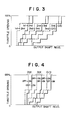
- Fig. 3 is a graph, in which power output shaft revolution speed, i.e. vehicle speed, is the abscissa, and throttle opening, i.e.
- engine load is the ordinate, relating specifically and only to operation in the drive or "D" range, showing upshift lines for from first speed stage to second speed stage, from second speed stage to third speed stage, and from third speed stage to overdrive speed stage, and also showing downshift lines for from second speed stage to first speed stage, from third speed stage to second speed stage, and from overdrive speed stage to third speed stage, for the hydraulically controlled transmission shown in Fig. 1 when said transmission is being controlled by the preferred embodiment of the transmission control device according to the present invention shown in Fig. 1 according to the preferred embodiment of the transmission control method according to the present invention.
- the digital control computer 33 inputs various data representative of vehicle operational parameters from various sensors of per se well known sorts via A/D converters and the like which are also per se well known, including data relating to engine throttle opening and transmission power output shaft revolution speed, and from this data determines from moment to moment the path on the graph of Fig. 3 taken by the point representing the transmission operational conditions.
- the computer 33 dispatches instructions to the solenoids Sl and S2 to engage the various ones of the friction engaging means of the gear transmission mechanism 7 which will cause the proper speed stages of the transmission to be engaged, as will be more fully explained later with reference to the flowcharts given in Figs. 5 through 8.
- these engage and disengage lines are again stored as explicit digital relationships between throttle opening (which is indicative of engine load) and transmission output shaft revolution speed (which is proportional to vehicle road speed), rather than being implicit in the operation of the transmission control system, as the corresponding theoretically well known engage and disengage lines are in the case of highest speed stage operation in the drive or "D" range of a conventional hydraulic fluid pressure lock up clutch control system incorporated in a conventional hydraulic fluid pressure transmission control system, which practices analog computation.
- Fig. 4 is a graph, in which power output shaft revolution speed, i.e. vehicle speed, is the abscissa, and throttle opening, i.e. engine load, is the ordinate, relating specifically and only to operation in the drive or "D" range, showing engagement lines (i.e.
- the computer 33 dispatches instructions to the solenoid S3 to engage or to disengage the lock up clutch 4, as will be more fully explained later with reference to the flowcharts given in Figs. 5 through 8.
- the separation between the engage and disengage lines for each speed stage is related to the concept of providing a hysteresis effect in the operation of the lock up clutch 4, with respect to its engagement and disengagement, so as to avoid hunting of the lock up clutch 4, i.e. repeated engagement and disengagement thereof within a short time period.
- other combinations of upshift and downshift lines like the lines shown in Fig. 3 are also stored by the computer 33, relative to other speed ranges.
- this timing for the engagement and disengagement of the lock up clutch during change of the transmission speed stage will probably be different for the various combinations of transmission speed stages which are to be shifted between, i.e. the first speed stage to and from the second speed stage, the second speed stage to and from the third speed stage, and the third speed stage to and from the overdrive speed stage, in the case of the transmission shown in the figures and described herein.
- Control starts in the START block, in which the various flags and other variables of the program are initialized, as will be detailed later. Then control passes to enter next the DATA INPUT block.
- data is read into the computer 33 relating to: the vehicle speed (actually the speed of rotation of the power output shaft 6 of the gear transmission mechanism 7, which is proportional to the vehicle speed); throttle opening or boost pressure; the position of the manual range selection valve which is operated by hand by the driver of the vehicle to select and set an appropriate range for operation of the transmission, such as drive or "D” range, third or “3" range, low or “L” range, reverse or “R” range, neutral or “N” range, and parking or “P” range; and whether the braking system of the vehicle is being applied at the moment or not. Then control passes to enter next the RANGE ? decision block.
- the vehicle speed actually the speed of rotation of the power output shaft 6 of the gear transmission mechanism 7, which is proportional to the vehicle speed
- throttle opening or boost pressure the position of the manual range selection valve which is operated by hand by the driver of the vehicle to select and set an appropriate range for operation of the transmission, such as drive or "D” range, third or “3" range, low or “L” range, reverse or
- control computer 33 In the SET LOCK UP CLUTCH OFF block, the control computer 33 outputs the proper signals to the solenoid S3 to cause the lock up clutch 4 of the gear transmission mechanism 7 to be disengaged. Then control passes to enter next the DATA INPUT block, and recycles. Thus, if the vehicle is being operated in any of the reverse or "R” range, the neutral or “N” range, or the “P” or parking range, the lock up clutch 4 is kept disengaged.
- a decision is made as to whether, based upon the current values of operational parameters of the vehicle and on the speed change graph which was selected in the SELECT SPEED CHANGE AND LOCK UP CLUTCH GRAPHS block, the currently set speed of the gear transmission mechanism 7 should be changed. If NO, then control passes to the point a in the flowchart of Fig. 6, i.e. passes to enter next the UPSHIFT ? decision block in Fig. 6, while if YES then a test is made as to whether the flag Fl is equal to 1 or not, in the Fl l ? decision block.
- the proper value for the time interval T0 is set, and the proper values for the time intervals Tl, T2, and T3. are set, for example by table look up from a table such as the table exemplarily shown in Fig. 10, with reference to the currently set speed stage of the gear transmission mechanism 7 and the current engagement or disengagement state of the lock up clutch 4, i.e. the engagement or disengagement state of the lock up clutch 4 before the speed stage change.
- TO is a constant time interval for determining, when a change of speed stage is to be made, whether up till that time point the lock up clutch 4 has been engaged or not, as will be more fully described later;
- Tl is the proper time interval from the instant that a speed stage change decision is made, i.e.
- T2 is the proper time interval from the instant that a speed stage change decision is made to the instant at which a lock up clutch disengage signal is to be output
- T3 is the proper time interval from the instant at which a lock up clutch disengage signal is to be output to the instant at which a lock up clutch engage signal ought to be output, in the case that the lock up clutch 4 should be engaged after the change of speed stage, i.e. is the time interval for temporary disengagement of the lock up clutch 4, during this upwards change of transmission speed stage.
- TM1 greater than Tl ? decision block a test is made as to whether the elapsed time as measured by the timer TM1 is greater than Tl or not, and if it is then control passes next to enter the OUTPUT SPEED CHANGE SIGNAL block, while otherwise this block is skipped.
- T1 is the proper time interval from the instant that a speed stage change decision is made, i.e. from the instant that the timer TM1 is reset as will be explained later, to the instant at which a speed stage change signal is to be output, as before; T2 is as will be seen from the table in Fig.
- T3 is the proper time interval from the instant at which a lock up clutch disengage signal is to be output to the instant at which a lock up clutch engage signal ought to be output, i.e. is the time interval for temporary disengagement of the lock up clutch 4, during this downwards change of transmission speed stage.
- TM3 greater than Tl ? decision block a test is made as to whether the elapsed time as measured by the timer TM3 is greater than Tl or not, and if it is then control passes next to enter the OUTPUT SPEED CHANGE SIGNAL block, while otherwise this block is skipped.
- T4 which is a constant
- the flag F6 is set to 0 or 1 according respectively as to whether the lock up clutch 4 should be set to the engaged or the disengaged state, i.e. according respectively as to whether the point representing the current operational condition of the vehicle on the lock up clutch engagement and disengagement graph like Fig. 4 selected as previously explained in the SELECT SPEED CHANGE AND LOCK UP CLUTCH GRAPHS block is in an area indicating engagement or disengagement of the lock up clutch 4, with respect to the new speed stage that the gear transmission mechanism 7 has been shifted to if in fact in the flowchart of Fig. 6 any speed stage change signal was output in the OUTPUT SPEED CHANGE SIGNAL block. Then control passes to enter next the decision block TM2 greater than T3 ?.
- the flag F3 is zero if and only if the braking system of the vehicle is not being applied, and the flag F4 is zero if and only if a longer time interval than T4 has elapsed since last the throttle of the engine of the vehicle was fully closed.
- the lock up clutch 4 will definitely not be engaged at any time if the braking system of the vehicle is being applied, or if the throttle of the vehicle has been closed at any time within the last time interval of length T4; and as explained earlier these two useful specializations of the present invention provide, respectively, protection against engine stalling during braking of the vehicle, and protection against transmission torque shock caused by sudden opening of the throttle after the throttle has been fully closed, i.e. snapping open of the throttle, because the lock up clutch 4 is definitely disengaged during both these cases, and accordingly the moderating effect of the torque converter 3 is available.
- the timer TM3 is allowed to start measuring time, and the time value stored in this timer TM3 will in fact represent the length of time since the lock up clutch 4 was last in the engaged condition. Further, since neither an upshift nor a downshift is currently being commanded, the timer TM2 is allowed to run, as can be seen from the control flow at the lower part of Fig. 6. Now, suppose that for the first time, as control flows around the flowchart, the result of the SPEED CHANGE ? decision block in Fig. 5 is YES, indicating that a change of speed stage of the gear transmission mechanism 7 is to be made.
- the timer TM2 starts to count time, and then the timer TM2 is allowed to continue counting. Therefore, for the moment, since the timer TM2 will be nearly at zero by the time the decision block TM2 greater than T3 ? in Fig. 8 is reached, definitely neither the flag F1 will be set to zero, nor will the flags F2 or F5 be set to zero. Accordingly, the value of the flag FI will not be disturbed, and will remain 1, until as suggested above the counted value of the time in TM2 becomes greater than T3, i.e.
- the control passes on to set the flag F5 to zero while resetting the flags Fl and F2 to zero, and finally to the decision block F3...F6 ALL ZERO ?, to decide on whether the lock up clutch 4 should be engaged or not.
- TM3 is counting time from the time instant when the lock up clutch 4 was last engaged or from the time instant when a decision was made for change of speed stage of the gear transmission mechanism 7; in the first case, the lock up clutch 4 is no longer engaged, so it is quite in order to shift the gear transmission mechanism 7 down immediately; and in the other case, a time interval longer than Tl has elapsed since the time of the speed change decision, and so (see Fig. 9b) it is time to output the speed change signal, and therefore control is transferred to the OUTPUT SPEED CHANGE SIGNAL block, in which the command signal to change the speed stage of the gear transmission mechanism 7 down is outputted.
- this part of the flowchart corresponds to the fact that in the table of Fig. 10 the values of T1 and T2 corresponding to upshifting with the lock up clutch disengaged before upshifting are all zero, as remarked on before.
- the branches of this flowchart involving the flag F2 are in order to protect the values of Tl and T2 from being made zero, if initially they were non zero and later the lock up clutch 4 is disengaged on a subsequent pass through the flowchart, as will be clear to one skilled in the art upon inspection of the control flow.
- the current counted time value in the timer TM1 is tested to see whether it is greater than Tl or not, and if it is then the time has come to perform the upshift, since a time interval longer than T1 has elapsed since the time of the speed change decision, (see Fig. 9a), and therefore control is transferred to the OUTPUT SPEED CHANGE SIGNAL block, in which the command signal to change the speed stage of the gear transmission mechanism 7 up is outputted.
- this time interval T2 is zero in the case of a downshift, and in the case of an upshift is the proper time that should elapse from the time point of first deciding to change the transmission speed stage to the time point of outputting a signal to disengage the lock up clutch 4 (if in fact the lock up clutch 4 is engaged, of course). Therefore, if it is not yet time to disengage the lock up clutch 4, then the flag F5 is set to zero. On the other hand, the flag F6 is set to zero when the transmission is operating in the condition with the lock up clutch 4 being engaged. Therefore, in this case, as long as the time measured by the timer TM1 does not exceed T2, the lock up clutch is kept engaged.
- the decision block in which it is decided whether or not the current time value measured on the timer TM2, in other words the time since a speed stage change signal was outputted, is greater than the time interval T3 or not; if it is, then the change of speed stages has been accomplished, and it is all right to reengage the lock up clutch. Accordingly, the flags F1 and F2 are reset to zero as has been explained already, and the flag F5 is set back to zero to allow the lock up clutch 4 to be engaged.
- the lock up clutch 4 is either engaged or disengaged, by supply to the solenoid S3 of either an engage or a disengage signal, according as to whether all four of the flags F3 through F6 are zero, or not.
- the lock up clutch 4 is engaged, unless (1) the flag F3 is not zero, which corresponds to the case that the braking system of the vehicle is being applied: (2) the flag F4 is not zero, which corresponds to the case that the throttle of the vehicle has been fully closed within the recent past, i.e.
- the flag F5 is not zero, which corresponds to the case that the time counted by the timer TM1 is greater than T2 and also the time counted by the timer TM2 is less than T3, i.e. the time, with reference to Fig. 9a or Fig. 9b, is between the time point for disengagement of the lock up clutch 4 and the subsequent time point for engagement of the lock up clutch 4, i.e. the lock up clutch 4 should be disengaged at this time for purposes of speed stage changing; or (4) the flag F6 is not zero, which corresponds to the case that the lock up clutch 4 should be disengaged in the current speed stage of the gear transmission mechanism 7. Otherwise, the lock up clutch 4 is disengaged.
- control computer 33 and transmission hydraulic fluid pressure control system 32 are comprised in and constitute the important portions of the preferred embodiment of the transmission control device according to the present invention.
- FIG. 11, 12, and 13 is a set of a first, a second, and a third synchronized explanatory graph, in all of which time is the abscissa, and in the first of which engine rotational speed is the ordinate, in the second of which transmission power output shaft torque is the ordinate, and in the third of which hydraulic fluid pressure is the ordinate.
- These figures all relate to a transmission upshift from second speed stage to third speed stage in drive or "D" range in which the lock up clutch 4 is engaged before the upshift and is to be engaged again after the upshift.
- the figures show, respectively, for the case when the lock up clutch 4 is not disengaged during the upshift at any time (which is most undesirable), for the case when the lock up clutch 4 is disengaged during the upshift with the time point of commencement of disengagement of the lock up clutch 4 substantially simultaneous with the time point of commencement of the upshift (which is better but still not good), and for the case when the lock up clutch 4 is disengaged during the upshift with the time point of commencement of disengagement of the lock up clutch 4 delayed by a certain time interval T2-T1 from the time point of commencement of the upshift (according to the shown first embodiment of the transmission control method according to the present invention), the variation with time of engine rotational speed, transmission power output shaft torque, hydraulic fluid pressure which is being supplied to the clutch C 2 or clutch 18 of Fig. 1 to engage it from the disengaged condition so as to accomplish the upshift, and hydraulic fluid pressure which is being supplied to the lock up clutch 4 to disengage it (when this is the case).
- the graphs shown in Figs. 11, 12, and 13 were produced by the present inventor in collaboration with others by a process of experiment. Although they relate only to the transmission upshift from second speed stage to third speed stage in drive or "D" range in which the lock up clutch 4 is engaged before the upshift and is to be engaged again after the upshift, in fact according to the shown preferred embodiment of the present invention a similar improvement may be attained in the other upshift cases in which the lock up clutch 4 may be engaged just before the upshift, such as the case of upshift from the third speed stage to the overdrive speed stage. In each case, the occurrence of engine racing is prevented by the practice of the shown preferred embodiment of the present invention, i.e.
Landscapes
- Engineering & Computer Science (AREA)
- General Engineering & Computer Science (AREA)
- Mechanical Engineering (AREA)
- Control Of Transmission Device (AREA)
- Control Of Fluid Gearings (AREA)
Applications Claiming Priority (2)
| Application Number | Priority Date | Filing Date | Title |
|---|---|---|---|
| JP56114062A JPS6032063B2 (ja) | 1981-07-21 | 1981-07-21 | 車輛用自動変速機の制御方法 |
| JP114062/81 | 1981-07-21 |
Publications (3)
| Publication Number | Publication Date |
|---|---|
| EP0072084A2 true EP0072084A2 (de) | 1983-02-16 |
| EP0072084A3 EP0072084A3 (en) | 1984-06-27 |
| EP0072084B1 EP0072084B1 (de) | 1987-12-02 |
Family
ID=14628071
Family Applications (1)
| Application Number | Title | Priority Date | Filing Date |
|---|---|---|---|
| EP82301772A Expired EP0072084B1 (de) | 1981-07-21 | 1982-04-02 | Vorrichtung und Verfahren zum exakten Steuern eines automatischen Getriebes mit Überbrückungskupplung |
Country Status (4)
| Country | Link |
|---|---|
| US (1) | US4495576A (de) |
| EP (1) | EP0072084B1 (de) |
| JP (1) | JPS6032063B2 (de) |
| DE (1) | DE3277776D1 (de) |
Cited By (5)
| Publication number | Priority date | Publication date | Assignee | Title |
|---|---|---|---|---|
| EP0164553A1 (de) * | 1984-05-12 | 1985-12-18 | Ford-Werke Aktiengesellschaft | Mehrgängiges, über ein hydraulisches Steuerventilsystem schaltbares, hydrokinetisch-mechanisches Wechselgetriebe für Kraftfahrzeuge |
| GB2203505A (en) * | 1987-03-11 | 1988-10-19 | Ford Motor Co | A control system for automatic transmission of a vehicle |
| EP0339664A3 (de) * | 1988-04-29 | 1991-04-24 | Chrysler Corporation | Verfahren zum Betreiben eines elektronisch gesteuerten automatischen Getriebesystems |
| DE19749767A1 (de) * | 1997-11-11 | 1999-05-12 | Zahnradfabrik Friedrichshafen | Automatisiertes Schaltgetriebe mit Drehmomentwandler |
| DE3790350C5 (de) * | 1986-06-30 | 2005-12-15 | Aisin AW Co., Ltd., Anjo | Steuereinrichtung für eine Überbrückungskupplung eines hydrodynamischen Drehmomentwandlers eines automatischen Getriebes |
Families Citing this family (49)
| Publication number | Priority date | Publication date | Assignee | Title |
|---|---|---|---|---|
| DE3470495D1 (en) * | 1983-06-01 | 1988-05-26 | Mazda Motor | Control means for vehicle automatic transmissions |
| JPH0730838B2 (ja) * | 1983-06-16 | 1995-04-10 | 日産自動車株式会社 | 無段変速機の制御装置 |
| CA1217834A (en) * | 1983-06-30 | 1987-02-10 | Toshihiro Hattori | Method of controlling gear changing operation in automatic transmission |
| JPS6011762A (ja) * | 1983-06-30 | 1985-01-22 | Isuzu Motors Ltd | 自動変速機の変速制御装置 |
| JPH0676825B2 (ja) * | 1983-07-04 | 1994-09-28 | 日産自動車株式会社 | トルクコンバ−タのスリツプ制御装置 |
| JPS6088259A (ja) * | 1983-10-19 | 1985-05-18 | Toyota Motor Corp | 車両用無段変速機の制御方法 |
| US4725951A (en) * | 1983-12-29 | 1988-02-16 | Nissan Motor Co., Ltd. | Control system for lock-up clutch in torque converter |
| JPS60175857A (ja) * | 1984-02-20 | 1985-09-10 | Diesel Kiki Co Ltd | 車輛用自動変速制御装置 |
| JP2545057B2 (ja) * | 1984-06-01 | 1996-10-16 | 日産自動車株式会社 | ロツクアツプ式自動変速機 |
| US4644826A (en) * | 1984-08-24 | 1987-02-24 | Toyota Jidosha Kabushiki Kaisha | Idling control system for an automatic transmission providing smooth starting off action |
| JPS6155455A (ja) * | 1984-08-24 | 1986-03-19 | Toyota Motor Corp | 車輌用自動変速機のアイドル運転時制御方法 |
| JPS6199753A (ja) * | 1984-10-19 | 1986-05-17 | Toyota Motor Corp | 自動変速機の変速制御装置 |
| JPS61127959A (ja) * | 1984-11-22 | 1986-06-16 | Toyota Motor Corp | 車両用自動変速機の変速制御方法 |
| JPS61144465A (ja) * | 1984-12-18 | 1986-07-02 | Mazda Motor Corp | 自動変速機の制御装置 |
| ES8800403A1 (es) * | 1985-07-17 | 1987-11-01 | Deere & Co | Un aparato para controlar la velocidad del motor y la realizacion de transmision de un vehiculo, tal como un tractor agricola. |
| JPS6262048A (ja) * | 1985-09-06 | 1987-03-18 | Komatsu Ltd | 電子制御式自動変速装置 |
| JPH0658134B2 (ja) * | 1985-10-31 | 1994-08-03 | マツダ株式会社 | 自動変速機の制御装置 |
| US4707789A (en) * | 1985-11-29 | 1987-11-17 | General Motors Corporation | Adaptive direct pressure shift control for a motor vehicle transmission |
| JPS62165051A (ja) * | 1986-01-13 | 1987-07-21 | Toyota Motor Corp | 自動変速機の制御方法 |
| JPS633467U (de) * | 1986-06-26 | 1988-01-11 | ||
| US4744269A (en) * | 1986-11-06 | 1988-05-17 | Ford Motor Company | Automatic transmission with lockup converter clutch controls |
| JPS63303258A (ja) * | 1987-06-02 | 1988-12-09 | Fuji Heavy Ind Ltd | ロックアップトルコン付無段変速機の制御装置 |
| JPH0694901B2 (ja) * | 1987-06-02 | 1994-11-24 | 富士重工業株式会社 | ロックアップトルコン付無段変速機の制御装置 |
| JPS6475291A (en) * | 1987-09-17 | 1989-03-20 | Hiromi Hamamori | Book made of cloth |
| US4953091A (en) * | 1988-10-24 | 1990-08-28 | Ford Motor Company | Automatic transmission torque converter clutch control |
| US5016175A (en) * | 1988-12-27 | 1991-05-14 | Ford Motor Company | Learned N/V ratio electronic control for automatic transmission reference speed in a driveline having unknown axle ratio |
| JPH02103561U (de) * | 1989-02-06 | 1990-08-17 | ||
| JP2685288B2 (ja) * | 1989-05-10 | 1997-12-03 | マツダ株式会社 | 流体継手のスリップ制御装置 |
| JPH0361726A (ja) * | 1989-07-28 | 1991-03-18 | Zexel Corp | 車輛用変速装置の制御方法 |
| US5460584A (en) * | 1989-12-26 | 1995-10-24 | Kabushiki Kaisha Komatsu Seisakusho | Method of controlling a lock-up clutch during down-shifting of hydraulic-actuated type multi-step transmission |
| JP2811912B2 (ja) * | 1990-05-18 | 1998-10-15 | トヨタ自動車株式会社 | 車両用自動変速機の制御装置 |
| JP2926959B2 (ja) * | 1990-10-17 | 1999-07-28 | トヨタ自動車株式会社 | 自動変速機の変速制御装置 |
| JPH04181058A (ja) * | 1990-11-15 | 1992-06-29 | Toyota Motor Corp | 自動変速機の変速制御装置 |
| US5038636A (en) * | 1991-02-07 | 1991-08-13 | General Motors Corporation | Double transition downshift control for an automatic transmission |
| US5434779A (en) * | 1991-10-15 | 1995-07-18 | General Motors Corporation | Adaptive pressure control for an automatic transmission |
| US5233890A (en) * | 1992-03-31 | 1993-08-10 | Saturn Corporation | Transmission torque converter clutch disable control |
| JP3262904B2 (ja) * | 1993-07-09 | 2002-03-04 | アイシン・エィ・ダブリュ株式会社 | 自動変速機 |
| JP3399062B2 (ja) * | 1993-12-22 | 2003-04-21 | トヨタ自動車株式会社 | 車両用自動変速機の故障検出装置 |
| JP3265881B2 (ja) * | 1994-11-29 | 2002-03-18 | アイシン・エィ・ダブリュ株式会社 | 自動変速機 |
| KR100257164B1 (ko) * | 1995-12-20 | 2000-05-15 | 정몽규 | 자동 변속 차량의 댐퍼 클러치 제어장치 및 그 방법 |
| JPH11294575A (ja) * | 1998-04-09 | 1999-10-29 | Nissan Motor Co Ltd | マニュアルレンジ付き自動変速機のロックアップ制御装置 |
| US6019703A (en) * | 1999-03-23 | 2000-02-01 | Daimlerchrysler Corporation | Transmission assembly for vehicle with torque converter clutch and method for engaging this clutch |
| JP2001099305A (ja) * | 1999-09-30 | 2001-04-10 | Nissan Motor Co Ltd | 自動変速機のロックアップ制御装置 |
| US6679806B2 (en) * | 2001-01-03 | 2004-01-20 | S & S Trust | Soft shift system and method |
| JP3753042B2 (ja) * | 2001-10-15 | 2006-03-08 | いすゞ自動車株式会社 | 排気ブレーキ装置の制御装置 |
| US8321107B2 (en) * | 2006-03-02 | 2012-11-27 | Volvo Lastvagnar Ab | Method and a device for controlling a disc clutch |
| US8630778B2 (en) * | 2008-08-08 | 2014-01-14 | Honda Motor Co., Ltd. | Controlling a throttle for fuel cut acquisition |
| US9731706B2 (en) | 2015-03-24 | 2017-08-15 | Ford Global Technologies, Llc | Coordinating non-demand engine start and stop with gear shift |
| US12385222B2 (en) | 2022-08-17 | 2025-08-12 | Caterpillar Inc. | Powertrain eco-mode for work machines |
Family Cites Families (14)
| Publication number | Priority date | Publication date | Assignee | Title |
|---|---|---|---|---|
| DE1750217A1 (de) * | 1968-04-09 | 1971-01-28 | Renk Ag Zahnraeder | Schaltvorrichtung und- verfahren fuer die UEberbrueckungskupplung an einem hydrodynamischen Drehmomentwandler |
| DE2431351B2 (de) * | 1974-06-29 | 1976-05-20 | Zahnradfabrik Friedrichshafen Ag, 7990 Friedrichshafen | Elektrohydraulische gangwechseleinrichtung eines lastschaltbaren wechselgetriebes fuer kraftfahrzeuge |
| DE2715999C2 (de) * | 1976-04-14 | 1984-01-19 | Kabushiki Kaisha Komatsu Seisakusho, Tokyo | Steuereinrichtung für ein automatisches Getriebe |
| US4148231A (en) * | 1977-04-25 | 1979-04-10 | Clark Equipment Company | Automatic transmission control |
| JPS5531669A (en) * | 1978-08-30 | 1980-03-06 | Toyota Motor Corp | Speed change timing instructor for vehicle speed change gear |
| FR2458725A1 (fr) * | 1979-06-13 | 1981-01-02 | Renault | Dispositif electronique de commande du pontage d'un convertisseur de couple hydrodynamique et procede de mise en oeuvre |
| US4393467A (en) * | 1979-09-01 | 1983-07-12 | Aisin-Warner Kabushiki Kaisha | Lockup controlling system for variable speed, automatic transmission |
| US4298105A (en) * | 1979-11-16 | 1981-11-03 | General Motors Corporation | Control valve mechanism for a power transmission |
| US4414863A (en) * | 1980-02-19 | 1983-11-15 | Deere & Company | Automatic electronic control for a power shift transmission |
| JPS602549B2 (ja) * | 1980-03-12 | 1985-01-22 | 日産自動車株式会社 | ロツクアツプ式自動変速機 |
| US4373619A (en) * | 1980-04-07 | 1983-02-15 | Grad-Line, Inc. | Transmission control system |
| JPS5776359A (en) * | 1980-10-31 | 1982-05-13 | Toyota Motor Corp | Method of controlling speed shifting operation of automatic transmission |
| DE3104299A1 (de) * | 1981-02-07 | 1982-08-19 | Robert Bosch Gmbh, 7000 Stuttgart | Vorrichtung zum steuern einer wandlerueberbrueckunskupplung |
| US4417303A (en) * | 1981-02-25 | 1983-11-22 | Leeds & Northrup Company | Multi-processor data communication bus structure |
-
1981
- 1981-07-21 JP JP56114062A patent/JPS6032063B2/ja not_active Expired
-
1982
- 1982-04-02 DE DE8282301772T patent/DE3277776D1/de not_active Expired
- 1982-04-02 EP EP82301772A patent/EP0072084B1/de not_active Expired
- 1982-04-05 US US06/365,306 patent/US4495576A/en not_active Expired - Lifetime
Cited By (6)
| Publication number | Priority date | Publication date | Assignee | Title |
|---|---|---|---|---|
| EP0164553A1 (de) * | 1984-05-12 | 1985-12-18 | Ford-Werke Aktiengesellschaft | Mehrgängiges, über ein hydraulisches Steuerventilsystem schaltbares, hydrokinetisch-mechanisches Wechselgetriebe für Kraftfahrzeuge |
| DE3790350C5 (de) * | 1986-06-30 | 2005-12-15 | Aisin AW Co., Ltd., Anjo | Steuereinrichtung für eine Überbrückungskupplung eines hydrodynamischen Drehmomentwandlers eines automatischen Getriebes |
| GB2203505A (en) * | 1987-03-11 | 1988-10-19 | Ford Motor Co | A control system for automatic transmission of a vehicle |
| GB2203505B (en) * | 1987-03-11 | 1991-07-10 | Ford Motor Co | A control system for controlling ratio changes in a multiple speed automatic transmission of a vehicle |
| EP0339664A3 (de) * | 1988-04-29 | 1991-04-24 | Chrysler Corporation | Verfahren zum Betreiben eines elektronisch gesteuerten automatischen Getriebesystems |
| DE19749767A1 (de) * | 1997-11-11 | 1999-05-12 | Zahnradfabrik Friedrichshafen | Automatisiertes Schaltgetriebe mit Drehmomentwandler |
Also Published As
| Publication number | Publication date |
|---|---|
| JPS5830558A (ja) | 1983-02-23 |
| EP0072084B1 (de) | 1987-12-02 |
| JPS6032063B2 (ja) | 1985-07-25 |
| EP0072084A3 (en) | 1984-06-27 |
| DE3277776D1 (en) | 1988-01-21 |
| US4495576A (en) | 1985-01-22 |
Similar Documents
| Publication | Publication Date | Title |
|---|---|---|
| US4495576A (en) | Device and method for accurately controlling automatic transmission with lockup clutch | |
| US4456107A (en) | Speed change control apparatus and method for automatic transmission | |
| US4486838A (en) | Apparatus and method for electronic control of automatic transmission avoiding over-quick double gear changing | |
| US5545108A (en) | Arrangement and method for controlling an automatic shift device of a gear-change transmission of a motor vehicle | |
| KR940002088A (ko) | 시프트 가능한 제어방법 및 장치 | |
| US6514173B2 (en) | Method and apparatus of controlling transmission system | |
| US5961420A (en) | Transmission control systems with shift determination based on pedal fluctuations within limits which vary with engine speed | |
| EP0175212B1 (de) | Steuerung eines automatischen Getriebes für ein Fahrzeug | |
| US5012699A (en) | Apparatus for controlling gearshifts in automatic transmission | |
| KR100551947B1 (ko) | 전기유압식으로 제어되는 자동변속기에서 오버랩핑 기어 시프트를 수행하기 위한 방법 | |
| US6866612B2 (en) | Control device for automatic transmission | |
| US4640393A (en) | Control device for vehicular transmission | |
| JP2516792B2 (ja) | 自動変速機の変速制御方法 | |
| US5075858A (en) | Shift control system for automatic transmission | |
| KR100561029B1 (ko) | 자동변속기에서 오버랩핑 기어 시프트를 수행하기 위한 방법 | |
| JPH0514138B2 (de) | ||
| JP3395979B2 (ja) | 自動変速機の制御装置 | |
| US5303615A (en) | Line pressure control of automatic transmission | |
| JPH05231533A (ja) | 自動変速機の制御装置 | |
| US5376058A (en) | Arrangement for control of line fluid pressure in automatic transmission | |
| JPH0621651B2 (ja) | 車両自動変速機の制御装置 | |
| JPH0633817B2 (ja) | 自動変速機の変速制御方法 | |
| JP2742269B2 (ja) | 自動変速機の変速制御装置 | |
| JP3155599B2 (ja) | 自動変速機の制御装置 | |
| JP3095517B2 (ja) | 自動変速機の制御装置 |
Legal Events
| Date | Code | Title | Description |
|---|---|---|---|
| PUAI | Public reference made under article 153(3) epc to a published international application that has entered the european phase |
Free format text: ORIGINAL CODE: 0009012 |
|
| AK | Designated contracting states |
Designated state(s): DE FR GB |
|
| RAP1 | Party data changed (applicant data changed or rights of an application transferred) |
Owner name: TOYOTA JIDOSHA KABUSHIKI KAISHA |
|
| PUAL | Search report despatched |
Free format text: ORIGINAL CODE: 0009013 |
|
| AK | Designated contracting states |
Designated state(s): DE FR GB |
|
| 17P | Request for examination filed |
Effective date: 19841214 |
|
| 17Q | First examination report despatched |
Effective date: 19860127 |
|
| R17C | First examination report despatched (corrected) |
Effective date: 19860903 |
|
| GRAA | (expected) grant |
Free format text: ORIGINAL CODE: 0009210 |
|
| AK | Designated contracting states |
Kind code of ref document: B1 Designated state(s): DE FR GB |
|
| REF | Corresponds to: |
Ref document number: 3277776 Country of ref document: DE Date of ref document: 19880121 |
|
| ET | Fr: translation filed | ||
| PLBE | No opposition filed within time limit |
Free format text: ORIGINAL CODE: 0009261 |
|
| STAA | Information on the status of an ep patent application or granted ep patent |
Free format text: STATUS: NO OPPOSITION FILED WITHIN TIME LIMIT |
|
| 26N | No opposition filed | ||
| REG | Reference to a national code |
Ref country code: GB Ref legal event code: 746 |
|
| REG | Reference to a national code |
Ref country code: FR Ref legal event code: DL |
|
| PGFP | Annual fee paid to national office [announced via postgrant information from national office to epo] |
Ref country code: DE Payment date: 20010326 Year of fee payment: 20 |
|
| PGFP | Annual fee paid to national office [announced via postgrant information from national office to epo] |
Ref country code: GB Payment date: 20010328 Year of fee payment: 20 |
|
| PGFP | Annual fee paid to national office [announced via postgrant information from national office to epo] |
Ref country code: FR Payment date: 20010409 Year of fee payment: 20 |
|
| REG | Reference to a national code |
Ref country code: GB Ref legal event code: IF02 |
|
| PG25 | Lapsed in a contracting state [announced via postgrant information from national office to epo] |
Ref country code: GB Free format text: LAPSE BECAUSE OF EXPIRATION OF PROTECTION Effective date: 20020401 |