EP0071895B1 - Kunststofform zum Abgiessen von Probewürfeln aus Beton - Google Patents
Kunststofform zum Abgiessen von Probewürfeln aus Beton Download PDFInfo
- Publication number
- EP0071895B1 EP0071895B1 EP82106865A EP82106865A EP0071895B1 EP 0071895 B1 EP0071895 B1 EP 0071895B1 EP 82106865 A EP82106865 A EP 82106865A EP 82106865 A EP82106865 A EP 82106865A EP 0071895 B1 EP0071895 B1 EP 0071895B1
- Authority
- EP
- European Patent Office
- Prior art keywords
- plastic
- mold
- concrete
- plastic mould
- test cubes
- Prior art date
- Legal status (The legal status is an assumption and is not a legal conclusion. Google has not performed a legal analysis and makes no representation as to the accuracy of the status listed.)
- Expired
Links
- 239000004033 plastic Substances 0.000 title claims abstract description 37
- 229920003023 plastic Polymers 0.000 title claims abstract description 37
- 238000000465 moulding Methods 0.000 title claims abstract 3
- 230000002093 peripheral effect Effects 0.000 claims abstract description 15
- 238000010276 construction Methods 0.000 claims abstract description 5
- 238000001125 extrusion Methods 0.000 claims abstract description 4
- 229920000098 polyolefin Polymers 0.000 claims abstract description 4
- 239000002184 metal Substances 0.000 claims description 7
- 239000000463 material Substances 0.000 description 7
- 239000000203 mixture Substances 0.000 description 7
- 238000005266 casting Methods 0.000 description 3
- 230000000694 effects Effects 0.000 description 3
- 238000004519 manufacturing process Methods 0.000 description 3
- 238000000034 method Methods 0.000 description 3
- -1 polypropylene Polymers 0.000 description 3
- 238000002360 preparation method Methods 0.000 description 3
- XLYOFNOQVPJJNP-UHFFFAOYSA-N water Substances O XLYOFNOQVPJJNP-UHFFFAOYSA-N 0.000 description 3
- 239000004743 Polypropylene Substances 0.000 description 2
- 229910000831 Steel Inorganic materials 0.000 description 2
- 238000005516 engineering process Methods 0.000 description 2
- 239000006260 foam Substances 0.000 description 2
- 229920001155 polypropylene Polymers 0.000 description 2
- 238000000926 separation method Methods 0.000 description 2
- 239000010959 steel Substances 0.000 description 2
- KXGFMDJXCMQABM-UHFFFAOYSA-N 2-methoxy-6-methylphenol Chemical compound [CH]OC1=CC=CC([CH])=C1O KXGFMDJXCMQABM-UHFFFAOYSA-N 0.000 description 1
- 239000004698 Polyethylene Substances 0.000 description 1
- 239000004793 Polystyrene Substances 0.000 description 1
- 238000004026 adhesive bonding Methods 0.000 description 1
- 230000002925 chemical effect Effects 0.000 description 1
- 238000004140 cleaning Methods 0.000 description 1
- 239000004035 construction material Substances 0.000 description 1
- 229920001577 copolymer Polymers 0.000 description 1
- 230000007797 corrosion Effects 0.000 description 1
- 238000005260 corrosion Methods 0.000 description 1
- 230000007812 deficiency Effects 0.000 description 1
- 229920001971 elastomer Polymers 0.000 description 1
- 239000003000 extruded plastic Substances 0.000 description 1
- 230000003993 interaction Effects 0.000 description 1
- 230000014759 maintenance of location Effects 0.000 description 1
- 229920001568 phenolic resin Polymers 0.000 description 1
- 239000005011 phenolic resin Substances 0.000 description 1
- 229920000573 polyethylene Polymers 0.000 description 1
- 229920005990 polystyrene resin Polymers 0.000 description 1
- 239000004814 polyurethane Substances 0.000 description 1
- 229920005749 polyurethane resin Polymers 0.000 description 1
- 238000003908 quality control method Methods 0.000 description 1
- 230000003014 reinforcing effect Effects 0.000 description 1
- 239000000126 substance Substances 0.000 description 1
- 239000002344 surface layer Substances 0.000 description 1
- 238000009423 ventilation Methods 0.000 description 1
- 238000013022 venting Methods 0.000 description 1
- 230000003245 working effect Effects 0.000 description 1
Images
Classifications
-
- B—PERFORMING OPERATIONS; TRANSPORTING
- B28—WORKING CEMENT, CLAY, OR STONE
- B28B—SHAPING CLAY OR OTHER CERAMIC COMPOSITIONS; SHAPING SLAG; SHAPING MIXTURES CONTAINING CEMENTITIOUS MATERIAL, e.g. PLASTER
- B28B7/00—Moulds; Cores; Mandrels
- B28B7/34—Moulds, cores, or mandrels of special material, e.g. destructible materials
- B28B7/348—Moulds, cores, or mandrels of special material, e.g. destructible materials of plastic material or rubber
-
- B—PERFORMING OPERATIONS; TRANSPORTING
- B28—WORKING CEMENT, CLAY, OR STONE
- B28B—SHAPING CLAY OR OTHER CERAMIC COMPOSITIONS; SHAPING SLAG; SHAPING MIXTURES CONTAINING CEMENTITIOUS MATERIAL, e.g. PLASTER
- B28B7/00—Moulds; Cores; Mandrels
- B28B7/0094—Moulds for concrete test samples
Definitions
- the invention relates to a plastic mold for pouring test cubes from concrete in the construction industry.
- test specimens are made of concrete in a cube shape with an edge length of 150 mm.
- molds of different types and of different materials are used, which can be divided into plastic and metal molds and these can also be divided into non-separable and separable forms.
- CSN 73 2400, 73 1311 and 73 1317 previously dismantable steel molds have been used in the CSSR, the disadvantages of which are the relatively high weight and short lifespan. These disadvantages are caused by the fact that the individual mold parts are damaged during handling, which in turn leads to an undesirable expansion of dimensional tolerances.
- plastic molds which have the advantages of chemical resistance and the low weight, which enables women to use them and which simplify mold manipulation.
- the domestic plastic molds are e.g. produced by gluing from plate semi-products. Such a procedure is cumbersome, places excessive demands on workers and is costly. Because of the limited strength of joints, the lifespan of such products is relatively short.
- DE-A-255 48 34 discloses a one-piece plastic mold for pouring test cubes out of concrete, which is made of rigid foam, e.g. Polyurethane, polystyrene or phenolic resin foam is made and has peripheral walls with reinforcing ribs and a closed bottom, the inner surfaces must be smooth.
- rigid foam e.g. Polyurethane, polystyrene or phenolic resin foam
- DE-B-261 48 46 discloses a one-piece plastic mold with peripheral walls, a bottom, a peripheral flange and a conical hole that narrows towards the mold cavity in the center of the bottom, metal parts being attached to the bottom as parking feet.
- the invention has for its object to provide an improved one-piece plastic mold for casting sample cubes from concrete, which has a high accuracy, a long life and a good separation effect even in the case of so-called plastic concrete types.
- the object of the invention is a plastic mold for casting test cubes from concrete, which are extruded from structurally foamed polyolefin with a density of 0.5 to 0.85 g / cm 3 as a peripheral wall with ribs and a bottom sandwich construction is made, which is stiffened by a peripheral flange with at least three projections and with 0.2 to 2.0 mm higher than its outer edge inner edge, and which in the middle of the bottom with a conical, towards the cavity of the mold expanding hole is provided.
- a metal insert is preferably pressed into the bottom of the plastic mold, and preferably its working surface is corrugated.
- the plastic mold according to the invention has high accuracy and a long service life. Their production is through a productive technology, i.e. Extrusion, feasible. Structurally foamed polyolefins, in particular polypropylene, are used as the construction material, which combines the advantages of the high dimensional stability and the resistance to chemical effects of concrete mixtures and is also inexpensive. Another advantage of this material is excellent separation effects, even in cases of extra sticky so-called plastic concrete types.
- the structurally extruded plastics have further advantages due to their material structure, which is free of internal tension, which is a prerequisite for the high dimensional and dimensional stability, and the possibility to press a metal insert into the mold base, which enables magnetic retention on a vibration table;
- An important advantage for the given application is the finely corrugated surface structure, which facilitates the ventilation of the mold cavity when filling and also the removal from the mold by allowing air to flow freely through the microchannels created as a result of the corrugation of the working surface.
- the relatively high production accuracy of the structurally foamed product has made it possible to construct the working cavity of the plastic mold with a minimum inclination of 0.3 mm per 150 mm length, without any difficulties in demolding being observed. Such a minimal bevel has a positive influence on the quality of the sample.
- the center hole which widens conically in the direction of the press cavity, has been experimentally proven to facilitate - the venting of the mixture during vibration. Used in the molds previously produced you see holes that widen in the opposite direction.
- the floor is covered with a film, a plate made of plastic or another material.
- flat structures act as pump valves and, when vibrated, cause the solidifying form content to be aerated.
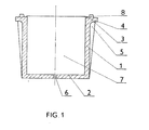
- the plastic mold is shown in a sectional view, which is guided in the region of the base 2 exactly through the center of the mold and in the region of the peripheral walls 1 in front of the stiffening ribs 5 thereof.
- the plastic mold consists of peripheral walls 1 and a base 2, so that a cavity 7 is created therein.
- the peripheral walls 1 merge into a raised inner edge 4 and into a stiffening peripheral flange 3. This is provided with four support projections 8.
- the plastic mold is produced using the technology of structural extrusion, which creates a homogeneous surface layer with fine corrugation or fine, thinly distributed microchannels with a maximum depth of 0.1 mm on the surface.
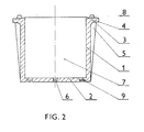
- Fig. 2 shows an alternative embodiment of the plastic mold for pouring concrete test cubes with an edge length of 150 mm, which differs from the first described only in that a e.g. annular metal insert 9 with good magnetic properties is placed in the cavity of the production mold before the plastic melt is injected.
- the material used is, for example, a copolymer of polypropylene with linear polyethylene.
- the two exemplary embodiments above are manufactured in terms of shape and dimensions in such a way that they correspond exactly to the shape and dimension conditions prescribed by the corresponding industrial standards.
- the preparation of test cubes in the plastic molds according to the invention is carried out in such a way that, before the cavity is filled, a plug made of concrete corresponding to the conical shape of the hole 6 of thicker consistency is formed and injected into the hole 6, after which the concrete mixture is injected poured.
- the filled plastic mold is then clamped to a vibration table using rubber bands or a magnetic plate. Because of the vibrations, the hole 6 in the base 2 of the plastic mold is completely sealed and an air residue escapes upwards, which the microchannels on the peripheral walls 1 promote. After the vibration has ended, the concrete mixture projecting over the inner edges 4 of the peripheral walls 1 is scraped off with a straight ruler.
- the base 2 of the plastic mold is tipped over and its contents are filled with a pressure medium, e.g. Water or air - demolded. Before that, you can loosen the cube to a certain extent by moderately lifting and lowering the shape onto the support projections 8. If warm water is available, the plastic mold is immersed in it within a few minutes before this process, after which the concrete cube easily falls out of the mold.
- a pressure medium e.g. Water or air - demolded.
- the plastic molds according to the invention are highly resistant to mechanical stress and retain their stable shape and dimensions even after more than two hundred uses.
- the quick handling during all processes of the preparation of test cubes is guaranteed by the interaction between the specific properties of plastic materials and the actual plastic mold construction.
Landscapes
- Engineering & Computer Science (AREA)
- Manufacturing & Machinery (AREA)
- Chemical & Material Sciences (AREA)
- Ceramic Engineering (AREA)
- Mechanical Engineering (AREA)
- Moulds, Cores, Or Mandrels (AREA)
- Sampling And Sample Adjustment (AREA)
- Forms Removed On Construction Sites Or Auxiliary Members Thereof (AREA)
- Compositions Of Macromolecular Compounds (AREA)
- Road Signs Or Road Markings (AREA)
- Molds, Cores, And Manufacturing Methods Thereof (AREA)
Description
- Die Erfindung betrifft eine Kunststofform zum Abgiessen von Probewürfeln aus Beton in der Bauindustrie.
- Für die Qualitätskontrolle von verschiedenen Betontypen nach den entsprechenden Industrienormen werden Probekörper aus Beton in Kubusform mit 150 mm Kantenlänge hergestellt. Zum Vorbereiten solcher Körper benutzt man Formen verschiedener Bauarten und aus verschiedenen Werkstoffen, die in Kunststoff- und Metallformen und diese ferner in unzerlegbare und zerlegbare Formen eingeteilt werden können. Für die Proben von Betongüte nach den Industrienormen CSN 73 2400, 73 1311 und 73 1317 wurden bisher in der CSSR meistens zerlegbare Stahlformen verwendet, deren Nachteile in verhältnismässig hohem Gewicht und kurzer Lebensdauer bestehen. Diese Nachteile sind dadurch verursacht, dass bei der Handhabung eine Beschädigung der einzelnen Formenteile erfolgt, was wiederum eine unerwünschte Ausweitung von Dimensionstoleranzen zur Folge hat. Darüber hinaus kommt es bei den Stahlformen auch zu erheblicher Materialkorrosion, was wiederum die Arbeitseigenschaften der Form beeinträchtigt und zu deren Ausserbetriebsetzung führt. Das nachteilige hohe Gewicht, das bei den Probewürfeln mit 200 mm Kantenlänge bis 25 kg erreicht, was samt Betonfüllung die Manipulation beträchtlich erschwert, erlaubt nicht den Einsatz des Frauenbedienungspersonals. Ein weiterer Nachteil von Metallformen liegt darin, dass Beton an den Formenwandungen festhaftet. Die Reinigung solcher Formen vor dem nächsten Giessprozess ist sehr mühsam und setzt die Formen auch Beschädigungsrisiken aus.
- Aus den vorstehenden Gründen geht man immer mehr zur Anwendung der Kunststofformen über, die die Vorteile der Chemikalienbeständigkeit und des niedrigen, die Frauenbedienung ermöglichenden und die Formenmanipulation sehr vereinfachenden Gewichts aufweisen. Die inländischen Kunststofformen werden z.B. durch Kleben aus Plattenhalbprodukten hergestellt. Ein solches Verfahren ist mühselig, stellt übermässige Ansprüche an die Arbeiter und ist kostspielig. Wegen beschränkter Festigkeit von Verbindungsstellen ist die Lebensdauer solcher Produkte verhältnismässig kurz.
- Weiter ist aus der DE-A-255 48 34 eine einstückige Kunststofform zum Abgiessen von Probewürfeln aus Beton bekannt, die aus Hartschaum, z.B. Polyurethan-, Polystyrol- oder Phenolharzschaum, hergestellt ist und Umfangswände mit Verstärkungsrippen und einen geschlossenen Boden aufweist, wobei die Innenflächen glatt sein müssen.
- Schliesslich ist hierfür aus der DE-B-261 48 46 eine einstückige Kunststofform mit Umfangswänden, einem Boden, einem Umfangsflansch und einem kegelförmigen, sich in Richtung zum Formhohlraum verengenden Loch in der Bodenmitte bekannt, wobei am Boden Metallteile als Abstellfüsse angebracht sind.
- Der Erfindung liegt die Aufgabe zugrunde, eine verbesserte einstückige Kunststofform zum Abgiessen von Probewürfeln aus Beton zu schaffen, die eine hohe Genauigkeit, eine lange Lebensdauer und einen guten Trenneffekt auch im Fall sog. Kunststoffbetontypen aufweist.
- Gegenstand der Erfindung, womit diese Aufgabe gelöst wird, ist eine Kunststofform zum Abgiessen von Probewürfeln aus Beton, welche durch Strangpressen aus strukturell geschäumtem Polyolefin von 0,5 bis 0,85 g/cm3 Dichte als eine Umfangswände mit Rippen und einen Boden aufweisenden Sandwichkonstruktion hergestellt ist, wobei sie durch einen Umfangsflansch mit mindestens drei Vorspüngen und mit um 0,2 bis 2,0 mm höher als seine Aussenkante stehender Innenkante versteift ist, und welche in der Mitte des Bodens mit einem kegelförmigen, sich in Richtung zum Hohlraum der Form erweiternden Loch versehen ist.
- Vorzugsweise ist in den Boden der Kunststoffform eine Metalleinlage eingepresst, und vorzugsweise ist ihre Arbeitsoberfläche geriffelt.
- Die erfindungsgemässe Kunststofform weist eine hohe Genauigkeit und lange Lebensdauer auf. Ihre Herstellung ist durch eine produktive Technologie, d.h. StrAngpressen, realisierbar. Als Konstruktionswerkstoff werden strukturell geschäumte Polyolefine, insbesondere Polypropylen, verwendet, das die Vorteile der hohen Formstabilität und der Beständigkeit gegen chemische Wirkungen von Betongemischen kombiniert und ausserdem billig ist. Ein weiterer Vorteil dieses Materials besteht in vorzüglichen Trenneffekten, sogar in Fällen von extra klebrigen sog. Kunststoffbetontypen. Die strukturell stranggepressten Kunststoffe besitzen weitere Vorteile durch ihre innenspannungsfreie Materialstruktur, die Voraussetzung der hohen Form- und Dimensionsstabilität ist, und die Möglichkeit, eine ein magnetisches Festhalten auf einem Vibrationstisch ermöglichende Metalleinlage in den Formenboden hineinzupressen; ein bedeutsamer Vorteil für die gegebene Anwendung besteht in der fein geriffelten Oberflächenstruktur, die die Entlüftung des Formenhohlraums beim Füllen und auch das Entformen dadurch erleichtert, dass Luft durch die infolge der Riffelung der Arbeitsoberfläche entstandenen Mikrokanäle frei strömen kann.
- Die relativ hohe Produktionsgenauigkeit des strukturell geschäumten Produkts hat es ermöglicht, die Konstruktion des Arbeitshohlraumes der Kunststofform mit minimaler Neigung von 0,3 mm pro 150 mm Länge zu bewerkstelligen, ohne dass Schwierigkeiten beim Entformen beobachtet wurden. Eine solche minimale Abschrägung beeinflusst positiv die Qualität des Probestückes.
- Ein wichtiges Bauelement der erfindungsgemässen Kunststofform ist die Anordnung ihres Bodens. Das Mittelloch, das sich in Richtung in den Presshohlraum konisch erweitert, erleichtertwie versuchsweise nachgewiesen worden ist - die Entlüftung des Gemisches bei der Vibration. Bei den bisher hergestellten Formen verwendete man nämlich Löcher, die sich in entgegengesetzter Richtung erweiterten. Um den Abfluss des frischen Betongemisches beim Einfüllen und bei der Vibration einer solchen Form zu vermeiden, wird der Boden mit einer Folie, einer Platte aus Kunststoff bzw. einem anderen Material bedeckt. Bei der Verikalbewegung des Vibrationstisches wirken solche Flächengebilde als Pumpenventile und verursachen bei der Vibration eine Durchlüftung des erstarrenden Forminhalts. Der Effekt eingesaugter Luft zeigt sich als Heben der frischen Betongemischfüllung im Bereich der Seitenwände der Form, wo die Füllung durch Wirkung der herausgepressten, gegen die Seiten der das Loch im Boden abdeckenden Folie gerichteten Luft gelüftet wird. Diese Erscheinung macht sich in Fällen von erdfeuchten und halbtrockenen Betongemischen, d.h. bei Gemischen mit niedrigem Wasserkoeffizient, bemerkbar. Das Ergebnis ist, das die Dichte der entformten Betonwürfel häufig in einem die durch die entsprechende Industrienorm bestimmte Toleranz überschreitenden Bereich schwankt. Diesem Mangel kann man teilweise so abhelfen, dass z.B. das Loch im Boden der Form vor dem Eingiessen des frischen Betongemisches mit Plastilin oder einem anderen geeigneten Kitt verkittet wird. Abgesehen davon, dass eine solche Massnahme den Arbeitsaufwand steigert, ist sie auch unzuverlässig. Die Dichte der entformten, in herkömmlichen unzerlegbaren Kunststofformen hergestellten Betonwürfel schwankt in Grenzen, die 10% überschreiten. Eine solche schwankende Musterdichte verschlechtert wesentlich die Qualität der Betonkontrolle und hat unnötige Betonverluste zur Folge. Bei der erfindungsgemässen Form mit dem in ihr Inneres sich erweiternden Bodenloch entfallen alle diese Schwierigkeiten.
- Bevorzugte Ausführungsbeispiele der erfindungsgemässen Kunststofform werden anhand der beigefügten schematischen Zeichnungen näher erläutert; darin zeigen:
- Fig. 1 eine vertikale Axialschnittansicht der Kunststofform; und
- Fig. 2 eine ähnliche Ansicht einer alternativen Ausführung derselben.
- Wie der Figur 1 entnehmbar, ist die Kunststoffform in einer Schnittansicht dargestellt, welche im Bereich des Bodens 2 genau durch die Mitte der Form und im Bereich der Umfangswände 1 vor den versteifenden Rippen 5 derselben geführt ist. Wie oben erwähnt, besteht die Kunststofform aus Umfangswänden 1 und einem Boden 2, so dass ein Hohlraum 7 darin entsteht. Am Oberteil gehen die Umfangswände 1 in eine erhöhte Innenkante 4 und in einen versteifenden Umfangsflansch 3 über. Dieser ist mit vier Stützvorsprüngen 8 versehen. In der Mitte des Bodens 2 ist ein konisches Loch 6 vorgesehen, das sich zum Hohlraum 7 der Kunststofform hin erweitert. Die Kunststofform ist durch die Technologie der strukturellen Strangpressen hergestellt, wodurch eine homogene Oberflächenschicht mit feiner Riffelung bzw. feinen, dünn verteilten Mikrokanälen mit einer maximalen Tiefe von 0,1 mm an der Oberfläche entsteht.
- Fig. 2 zeigt eine alternative Ausführung der Kunststofform zum Abgiessen von Betonprobewürfeln mit 150 mm Kantenlänge, die sich von der zuerst beschriebenen nur darin unterscheidet, dass eine z.B. ringförmige Metalleinlage 9 mit guten magnetischen Eigenschaften in den Hohlraum der Herstellungsform vor dem Einspritzen der Kunststoffschmelze hineingelegt wird. Als Werkstoff verwendet man beispielsweise ein Mischpolymerisat von Polypropylen mit linearem Polyäthylen.
- Die beiden obigen Ausführungsbeispiele sind form- und dimensionsgemäss so gefertigt, dass sie den durch die entsprechenden Industrienormen vorgeschriebenen Form- und Dimensionsbedingungen genau entsprechen.
- In der Praxis wird die Vorbereitung von Probewürfeln in den erfindungsgemässen Kunststoffformen so vorgenommen, dass man vor dem Ausfüllen des Hohlraumes einen etwa der konischen Form des Loches 6 entsprechenden Stopfen aus Beton von dickerer Konsistenz ausbildet und diesen in das Loch 6 einspritzt, worauf man das Betongemisch eingiesst. Die gefüllte Kunststofform wird dann an einen Vibrationstisch mittels Kautschukbänder bzw. einer magnetischen Platte angeklemmt. Wegen der Vibrationen wird das Loch 6 im Boden 2 der Kunststofform vollkommen abgedichtet, und ein Luftrest entweicht nach oben, was die Mikrokanäle an den Umfangswänden 1 fördern. Nach der Beendigung der Vibration wird das über die Innenkanten 4 der Umfangswände 1 ragende Betongemisch mit einem geraden Lineal abgestreift. Nach dem Erstarren des Betons wird die Kunststofform mit ihrem Boden 2 nach oben umgekippt und ihr Inhalt mit einem durch einen zu dessen Loch 6 gebrachten Schlauch zugeführten Druckmedium - z.B. Wasser oder Luft - entformt. Vorher kann man den Würfel durch mässiges Heben und wieder Senken der Form auf die Stützvorsprünge 8 gewissermassen auflockern. Steht warmes Wasser zur Verfügung, wird die Kunststofform vor diesem Vorgang innerhalb einiger Minuten darin eingetaucht, worauf der Betonwürfel leicht aus der Form herausfällt.
- Die erfindungsgemässen Kunststofformen sind hoch beständig gegen mechanische Beanspruchung und behalten ihre stabile Form und Dimensionen sogar nach mehr als zweihundertfachem Einsatz. Die rasche Handhabung während aller Vorgänge der Vorbereitung von Probewürfeln wird durch die Wechselwirkung zwischen den spezifischen Eigenschaften von Kunststoffmaterialien und der eigentlichen Kunststofformkonstruktion gewährleistet.
Claims (3)
Priority Applications (1)
| Application Number | Priority Date | Filing Date | Title |
|---|---|---|---|
| AT82106865T ATE17674T1 (de) | 1981-08-04 | 1982-07-29 | Kunststofform zum abgiessen von probewuerfeln aus beton. |
Applications Claiming Priority (2)
| Application Number | Priority Date | Filing Date | Title |
|---|---|---|---|
| CS5893/81 | 1981-08-04 | ||
| CS815893A CS223266B1 (en) | 1981-08-04 | 1981-08-04 | Plast mould for casting the concrete experimental cubes |
Publications (3)
| Publication Number | Publication Date |
|---|---|
| EP0071895A2 EP0071895A2 (de) | 1983-02-16 |
| EP0071895A3 EP0071895A3 (en) | 1983-07-20 |
| EP0071895B1 true EP0071895B1 (de) | 1986-01-29 |
Family
ID=5404737
Family Applications (1)
| Application Number | Title | Priority Date | Filing Date |
|---|---|---|---|
| EP82106865A Expired EP0071895B1 (de) | 1981-08-04 | 1982-07-29 | Kunststofform zum Abgiessen von Probewürfeln aus Beton |
Country Status (7)
| Country | Link |
|---|---|
| EP (1) | EP0071895B1 (de) |
| AT (1) | ATE17674T1 (de) |
| CS (1) | CS223266B1 (de) |
| DD (1) | DD230348A3 (de) |
| DE (1) | DE3268808D1 (de) |
| HU (1) | HU193640B (de) |
| YU (1) | YU167882A (de) |
Families Citing this family (7)
| Publication number | Priority date | Publication date | Assignee | Title |
|---|---|---|---|---|
| JP2787281B2 (ja) * | 1994-09-20 | 1998-08-13 | 株式会社ジェイエスピー | 凹凸模様を有するコンクリート面形成用化粧型及び凹凸模様を有するコンクリート面の形成方法 |
| AT4437U3 (de) * | 2001-01-19 | 2002-02-25 | Schotter Und Betonwerk Karl Sc | Beton-probewürfelform aus kunststoff mit prüfdruckflächen |
| CN109049293A (zh) * | 2018-09-29 | 2018-12-21 | 山东大学 | 充气式脱落的混凝土试块模具及方法 |
| AT521840B1 (de) * | 2018-11-06 | 2021-04-15 | Franz Filzmoser Mag | Verfahren zur Herstellung von Betonfertigteilen mit Hilfe einer Gussform |
| US11384548B2 (en) * | 2019-04-12 | 2022-07-12 | DPR Construction | Sleeve for concrete slab penetration |
| CN110303576A (zh) * | 2019-07-23 | 2019-10-08 | 济南城建集团有限公司 | 一种水泥浆充填塑料模具雨水口 |
| CN115972375A (zh) * | 2022-11-08 | 2023-04-18 | 山东大学 | 一种装配式带肋空心路缘石模具及应用方法 |
Family Cites Families (2)
| Publication number | Priority date | Publication date | Assignee | Title |
|---|---|---|---|---|
| DE2554834A1 (de) * | 1975-12-05 | 1977-06-08 | Rolf Dipl Ing Pfeifer | Neue schalungsformen zur herstellung von probekoerpern aus beton oder moertel |
| DE2614846C2 (de) * | 1976-04-06 | 1978-04-20 | Schlosser & Co Gmbh, 6209 Aarbergen | Form für Beton-Probekörper |
-
1981
- 1981-08-04 CS CS815893A patent/CS223266B1/cs unknown
-
1982
- 1982-07-27 DD DD82241908A patent/DD230348A3/de not_active IP Right Cessation
- 1982-07-29 EP EP82106865A patent/EP0071895B1/de not_active Expired
- 1982-07-29 AT AT82106865T patent/ATE17674T1/de not_active IP Right Cessation
- 1982-07-29 DE DE8282106865T patent/DE3268808D1/de not_active Expired
- 1982-08-02 YU YU01678/82A patent/YU167882A/xx unknown
- 1982-08-03 HU HU822501A patent/HU193640B/hu unknown
Non-Patent Citations (1)
| Title |
|---|
| KUNSTSTOFF-TASCHENBUCH,Hansjürgen Saechtling,20.Auflage,1977.CARL HAUSER VERLAG,München Wien * |
Also Published As
| Publication number | Publication date |
|---|---|
| DE3268808D1 (en) | 1986-03-13 |
| EP0071895A3 (en) | 1983-07-20 |
| YU167882A (en) | 1984-12-31 |
| DD230348A3 (de) | 1985-11-27 |
| CS223266B1 (en) | 1983-09-15 |
| ATE17674T1 (de) | 1986-02-15 |
| EP0071895A2 (de) | 1983-02-16 |
| HU193640B (en) | 1987-11-30 |
Similar Documents
| Publication | Publication Date | Title |
|---|---|---|
| EP0071895B1 (de) | Kunststofform zum Abgiessen von Probewürfeln aus Beton | |
| WO1990010533A1 (de) | Verfahren und vorrichtung zur herstellung von leichtbauplatten | |
| EP0494919A1 (de) | Plattenförmiger beton-formstein sowie verfahren und vorrichtung zum herstellen desselben. | |
| WO2004091877A1 (de) | Verfahren zum herstellen eines schachtbodens | |
| CH676943A5 (de) | ||
| EP0394835B1 (de) | Skiherstellungsverfahren und Ski, hergestellt nach diesem Verfahren | |
| DE69000858T2 (de) | Verfahren zum formen von betonwaenden. | |
| EP3649032A1 (de) | Ballastanordnung für ein schienenfahrzeug und verfahren zum herstellen einer ballastvorrichtung | |
| DE3002939A1 (de) | Duese zum entlueften, belueften oder bedampfen von formen | |
| DE3719700A1 (de) | Giessform fuer sanitaergegenstaende und verfahren zum herstellen einer solchen giessform | |
| CH662777A5 (de) | Schaeumform zum herstellen von druckmittelkanaele aufweisenden adapterbloecken sowie verfahren zur herstellung einer solchen schaeumform und verfahren zum herstellen von adapterbloecken. | |
| DE60117636T2 (de) | Tablett-ähnliche Schalungsform zur Herstellung von Betonplatten | |
| DE4113752A1 (de) | Verfahren zur herstellung von betonformteilen | |
| DE2811024A1 (de) | Tragendes bauelement fuer den wohnungs-, wirtschafts- und industriebau | |
| DE10311124B4 (de) | Verfahren zum Herstellen einer Betonplatte mit einer verschiedenfarbigen Sichtseite | |
| DE19525315A1 (de) | Hohlraumboden | |
| DE102005017643B4 (de) | Geschlossene Hohlform zur Verwendung in einem Stein,Stein, Steinverbund | |
| CH403385A (de) | Pflanzengefäss mit Bewässerungsvorrichtung | |
| DE3933510A1 (de) | Verfahren und anordnung zum messen der eigenschaften einer steifen, komprimierbaren masse | |
| DE1917242C3 (de) | Form zur Herstellung eines Probekörpers aus erstarrtem Beton | |
| EP0004866A1 (de) | Form zum gleichzeitigen Herstellen mehrerer Betonhohlblocksteine | |
| DE19915147C2 (de) | Verfahren zur Herstellung eines gestalteten Kontrollschachtes | |
| DE102021133963A1 (de) | Verfahren zur Herstellung eines Bauteils im Wege der additiven Fertigung | |
| DE29622081U1 (de) | Hilfsvorrichtung für eine Verlegung von insbesondere Betonformsteinen | |
| DE102018110520A1 (de) | Werkzeug und Verfahren zur Reparatur von flächigen Materialien |
Legal Events
| Date | Code | Title | Description |
|---|---|---|---|
| PUAI | Public reference made under article 153(3) epc to a published international application that has entered the european phase |
Free format text: ORIGINAL CODE: 0009012 |
|
| AK | Designated contracting states |
Designated state(s): AT DE FR GB IT SE |
|
| PUAL | Search report despatched |
Free format text: ORIGINAL CODE: 0009013 |
|
| AK | Designated contracting states |
Designated state(s): AT DE FR GB IT SE |
|
| 17P | Request for examination filed |
Effective date: 19831227 |
|
| RBV | Designated contracting states (corrected) |
Designated state(s): AT DE FR GB |
|
| GRAA | (expected) grant |
Free format text: ORIGINAL CODE: 0009210 |
|
| AK | Designated contracting states |
Designated state(s): AT DE FR GB |
|
| REF | Corresponds to: |
Ref document number: 17674 Country of ref document: AT Date of ref document: 19860215 Kind code of ref document: T |
|
| REF | Corresponds to: |
Ref document number: 3268808 Country of ref document: DE Date of ref document: 19860313 |
|
| ET | Fr: translation filed | ||
| PGFP | Annual fee paid to national office [announced via postgrant information from national office to epo] |
Ref country code: AT Payment date: 19860715 Year of fee payment: 5 |
|
| PLBE | No opposition filed within time limit |
Free format text: ORIGINAL CODE: 0009261 |
|
| STAA | Information on the status of an ep patent application or granted ep patent |
Free format text: STATUS: NO OPPOSITION FILED WITHIN TIME LIMIT |
|
| 26N | No opposition filed | ||
| PG25 | Lapsed in a contracting state [announced via postgrant information from national office to epo] |
Ref country code: GB Effective date: 19890729 Ref country code: AT Effective date: 19890729 |
|
| GBPC | Gb: european patent ceased through non-payment of renewal fee | ||
| PG25 | Lapsed in a contracting state [announced via postgrant information from national office to epo] |
Ref country code: FR Free format text: LAPSE BECAUSE OF NON-PAYMENT OF DUE FEES Effective date: 19900330 |
|
| PG25 | Lapsed in a contracting state [announced via postgrant information from national office to epo] |
Ref country code: DE Effective date: 19900403 |
|
| REG | Reference to a national code |
Ref country code: FR Ref legal event code: ST |