EP0071856A1 - Zuführeinrichtung für Fahrradspeichen an einer Einspeichmaschine - Google Patents
Zuführeinrichtung für Fahrradspeichen an einer Einspeichmaschine Download PDFInfo
- Publication number
- EP0071856A1 EP0071856A1 EP82106717A EP82106717A EP0071856A1 EP 0071856 A1 EP0071856 A1 EP 0071856A1 EP 82106717 A EP82106717 A EP 82106717A EP 82106717 A EP82106717 A EP 82106717A EP 0071856 A1 EP0071856 A1 EP 0071856A1
- Authority
- EP
- European Patent Office
- Prior art keywords
- ramp
- spoke
- spokes
- drum
- knife
- Prior art date
- Legal status (The legal status is an assumption and is not a legal conclusion. Google has not performed a legal analysis and makes no representation as to the accuracy of the status listed.)
- Withdrawn
Links
Images
Classifications
-
- B—PERFORMING OPERATIONS; TRANSPORTING
- B23—MACHINE TOOLS; METAL-WORKING NOT OTHERWISE PROVIDED FOR
- B23P—METAL-WORKING NOT OTHERWISE PROVIDED FOR; COMBINED OPERATIONS; UNIVERSAL MACHINE TOOLS
- B23P19/00—Machines for simply fitting together or separating metal parts or objects, or metal and non-metal parts, whether or not involving some deformation; Tools or devices therefor so far as not provided for in other classes
- B23P19/001—Article feeders for assembling machines
-
- B—PERFORMING OPERATIONS; TRANSPORTING
- B60—VEHICLES IN GENERAL
- B60B—VEHICLE WHEELS; CASTORS; AXLES FOR WHEELS OR CASTORS; INCREASING WHEEL ADHESION
- B60B31/00—Apparatus or tools for assembling or disassembling wheels
- B60B31/005—Apparatus or tools for assembling or disassembling wheels especially for spoked wheels
Definitions
- the present invention relates to a device for automatically feeding the spokes one by one from a reservoir to a machine making it possible to introduce the spokes into the holes of a spoke wheel hub.
- Threading the spokes into the spoked wheel hubs is a meticulous and delicate operation which has hitherto been carried out manually. Machines are being developed to allow this threading to be carried out automatically. It is then necessary to supply these devices with spokes, these spokes being arranged in a determined position.
- the spokes generally comprise a straight cylindrical rod, one end of which is curved and has a head of larger diameter. To carry out a correct threading, certain devices require that the head be positioned in a determined direction, on the one hand to allow the passage of the ray in the radiating machine, and on the other hand to ensure a good positioning of the ray on the spoke wheel hub
- US Patent 2,823,830 describes means for bringing the screws into good position by a rotary conveyor disposed between two pipes. This device does not ensure true selection and is inapplicable to the shape of the spokes.
- An object of the present invention is to provide a ray distributor making it possible to automatically present the rays one by one and bringing them to a predetermined position in the radiating machine.
- the radiating machine comprises a substantially horizontal chute and into which the spoke rod must be inserted, the spoke head being disposed above the chute.
- the device must bringing the spokes into a substantially horizontal position, by translation from top to bottom, the spoke head being directed upwards.
- the chute is wider and it suffices that the radius is in the right direction, whatever the inclination of the head.
- Another object of the present invention is to provide a dispenser making it possible to avoid the presentation of two rays at the same time, although the shape of the rays with a curved head tends to cause them to spit out and their simultaneous training.
- Another object of the invention is to provide a dispenser which particularly avoids jamming the spokes and blocking the device.
- the spokes are presented in a very short time, so as to limit the dead times and increase the rate of the rayonnero machine
- the dispenser comprises a spoke reservoir in which the spokes are arranged in a horizontal position, a knife device making it possible to select the spokes and bring them one by one from the reservoir to a descending guide ramp; a drum is rotated along a transverse axis; it is provided with peripheral grooves parallel to its axis and of section greater than the section of the spoke rods.
- the drum is arranged downstream of the guide ramp to receive the spokes in its grooves, and is associated with fixed stops such as a scraper; thus the rotation of the drum simultaneously ensures the selection of the spokes, their intermediate storage in disjoined queue, and their transport from the guide ramp to a discharge ramp.
- the guide device comprises two substantially parallel inclined surfaces, arranged one opposite the other at a predetermined distance to allow the sliding of a ray between them, the first surface or surface upper being slippery, the second surface or lower surface being of an adherent material to produce on the spoke a torque when it slides, the first surface then blocking the rotation of the head for the hand stand above the rod.
- the first surface has a width at least equal to the length of the spoke, so that the spoke head comes to bear slidingly against it, the second surface having a smaller width to release the head from Ray ; the distance between the two surfaces is greater than the diameter of the spoke rod and less than half the sum of the diameter of the rod and the diameter of the spoke head.
- the knife selection device comprises two consecutive knives, a first knife with a large clearance, followed by a second knife with a lower clearance but with a higher position.
- the device freely selects the departments in the tank until a department is presented ready to be ejected, the device then being kept in the waiting state. This reduces the transit times of the spokes, without suffering any delays due to the fact that the tangle of spokes in the tank does not allow the knife to separate a spoke with each movement.
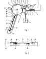
- the dispenser comprises a reservoir 1, the bottom 2 of which is inclined towards its outlet end 3.
- the spokes 4 are arranged horizontally in the reservoir 1, and represented according to their cross section in FIG. 1. Their two ends are guided by the lateral flanks of the tank 1, these lateral flanks being able to be at an adjustable distance from one another to adapt to radii of different lengths.
- a fixed stop 5 causes the thickness of the spoke layer to be reduced, so as to reduce the number of spokes occurring simultaneously in the vicinity of the end 3.
- the reservoir 1 is limited at its outlet end 3 by a knife 6, comprising a horizontal upper end 7 of thinned section, and driven by a vertical reciprocating translational movement, under the action of drive means 8.
- the knife 6 is movable between a first position, shown in dotted lines in FIG. 1, in which its upper end 7 is flush with the bottom 2 of the reservoir 1, and a second position, shown in solid lines, in which the upper end 7 is raised and flush with an inclined ramp 9 on which the spoke slides and abuts against a rotary drum 10 of substantially horizontal axis
- the drum 10 has longitudinal peripheral grooves 11 of section greater than the section of the spoke rod.
- the drum 10 driven in rotation in the direction represented by the arrow 12, drives the spokes inserted in the grooves 11.
- each groove is preceded by a flat 13, so that the front lip 14 of the groove is slightly lower than the lip 15 of this same groove.
- This produces a fastening structure allowing the gradual approximation of the radius rod of the axis of rotation of the drum 10, and its insertion in the groove 11.
- the ramp 9 comes flush with the drum 10 slightly above the horizontal diameter passing through the axis of rotation of the drum 10.
- the present invention also provides means for avoid the insertion and the catching of several spokes on the drum in the case where several spokes are driven by the knife 60
- a first fixed stop 16 disposed above the ramp 9 and the knife 6, at a distance slightly greater than the diameter of the spoke, defines an introduction corridor avoiding the overlapping of the spokes.
- the spout 17 of this stop 16 presses the spokes and optionally causes them to rotate against the cylinder and lets through only the spokes inserted in a groove 11.
- a second fixed stop 18, or scraper, disposed above the first, has a end positioned in abutment on the surface of the drum 10, to ensure that the spoke driven by the drum is properly inserted over its entire length in the groove 11 and to drop a second driven ray if necessary with the first spoke inserted in the groove.
- a cylindrical cover 19 covers the upper part of the drum 10, between the second stop 18 and the opposite drop of the drum, to maintain the spokes in the grooves throughout their journey. After the end 20 of the cover, the spokes fall on slides 21 bringing them onto a guide device 220
- a detector 23 is placed in the vicinity of the end 20 of the cover 19, this detector controlling the stopping of the knife 6 and of the drum 10 when a spoke is present in a groove 11 opposite the detector 23.
- the movement of the drum 10 and the knife 6 is again launched as soon as a radius expulsion order is given to the device by the control members of the beaming machine.
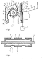
- the guide device 22 comprises two inclined and substantially parallel surfaces, arranged one opposite the other to allow the sliding of a spoke between them, a first surface 24, or upper surface, has a slippery and smooth lower face. to allow a ray to slide against it.
- a second surface 25, or lower surface has an upper face made of an adherent material, so that this second surface produces on the spoke a torque when it falls, as shown by arrow 26o
- the upper surface 24 has a width greater than the length of the spoke, so that the spoke head 27 comes to bear against this surface, while the lower surface 25 has a width less than the length of the spoke to allow free rotation of the head 27.
- the surfaces 24 and 25 may not be continuous, and constituted for example by disjoint inclined metal bands: the upper surface 24, in the embodiment shown, comprises two metal bands 28 and 29, arranged at the two ends of the spoke, and the lower surface 25 comprises two bands 30 and 31, a first band 30 being for example - ple disposed at a quarter of the length of the rod 32 of radius starting from the head 27 and the second strip 31 being arranged opposite strip 29 in the vicinity of the other end of the spoke.
- the strips 30 and 31 are covered with layers 33 and 34 of adhesive material such as rubber.
- the distance between the planes formed by the upper 24 and lower 25 surfaces is adjusted so as to allow the rotation of the rod 32 on the bands 30 and 31, the sliding of this rod on the upper band 29, and the sliding support of the head 27 against the strip 28.
- a distance between these two surfaces will preferably be chosen between the thickness of the rod 32 and the half sum of the diameters of the rod 32 and of the head 27.
- the spoke After sliding between the surfaces 24 and 25, the spoke falls into a chute 34 forming part of the radiating machine. To ensure correct positioning of the spoke in the chute, it is preferable to position the guide device 22 so that its lower end comes flush with the chute 34. In this case, it may be necessary to provide means for escaping the guide device 22 after insertion of a spoke into the chute 34, which can be achieved by providing to mount this guide device 22 on a rotary support, rotating for example around the axis 35 of the drum 10, and driven by drive means not shown in the figures.
- the following embodiment may be preferred, in which the selection means associated with the rotary drum have been modified.
- this second embodiment will be described in relation to a modified and simplified discharge ramp 22, which no longer ensures the systematic positioning of the ray head upwards at the outlet of the ramp.
- This simplified embodiment of the discharge ramp is suitable for use in which it is not necessary to fix the position of this spoke head. We can of course associate this simplified embodiment of the discharge ramp with the first embodiment of the selection means described above.
- FIGS. 3 and 4 This second embodiment is illustrated by FIGS. 3 and 4.
- the bottom 2 of the reservoir 1 comprises two successive flat parts 40 and 41 forming a re-entrant dihedral, as shown in FIG. 3, connected along a line 42 transverse to the direction 43 of ray progression.
- This arrangement favors the parallelism of the spokes and their transverse positioning in the tank. It can also be used in the embodiment of Figures 1 and 2. It is also possible to use a continuously curved bottom 2 defined by horizontal transverse generators, such as a portion of cylinder
- the selection device at the outlet 3 of the reservoir comprises a first knife 44, driven by a vertical reciprocating translational movement, under the action of drive means 8.
- the knife 44 is movable between a first position, shown in solid lines in the figure, in which the upper edge 45 is flush with the bottom 2 of the reservoir 1, and a second position, shown in dotted lines, in which the upper edge 45 reaches the level of an intermediate ramp 46 leading to a second knife 47.
- the second knife is driven by a vertical reciprocating translational movement in synchronism with the first knife. It is movable between a lower position, shown in solid lines in the figure, in which its upper edge is flush with the intermediate ramp 46, and an upper position in which its upper edge reaches the level of an upper ramp 48.
- the upper ramp 48 is connected to the guide ramp 9 by a jump. However, it is possible to provide ramps 9 and 48 on the same level. Tests have shown that the first knife 44 must have a large vertical reduction, for example of the order of half the length of the rod of a spoke, while the second knife can have a lower clearance.
- the thickness of the first knife is chosen so as to allow the insertion of one to three spokes on its upper edge. This thickness is substantially the same as the sum of the thicknesses of the second knife and of the intermediate ramp 46 0
- the second knife has a reduced thickness, so as to take only one radius at a time.
- the rotary drum 10, driven in rotation about the transverse axis 35-by a drive motor not shown in the figure, has a substantially cylindrical outer surface cut by longitudinal peripheral grooves 11, parallel to the axis 35, of section sufficient to admit the rod of a spoke.
- Magnets 49 are arranged in the bottom of the grooves 11, which promote the drive of only one spoke at a time and press the rod in the bottom of the groove throughout its transport by the drum.
- a scraper 50 is disposed at the start of the upper part of the drum, as shown in the figure, near its outer surface.
- circular peripheral grooves 51 are formed on the drum, deeper than the grooves 11, and in which the upper ends 52 in the form of a comb of the ramp are housed. evacuation 220
- the discharge ramp 22 is simplified, and leads along a short path the spokes in a wide chute 34.
- the inclination of the spoke head relative to the rod does not matter in this device.
- the drive of the second knife 47 can be ensured by the first knife 44.
- the first knife is secured to a rod 53 coming to bear against the lower edge of the second knife and to lift it during the end of travel of the first knife.
- a stop 54 limits the stroke of the second knife towards the base Tests have shown that the height of the ramp 22 should be limited as much as possible to avoid bouncing of spokes and reducing their fall time
- a first detector 55 at the level of the guide ramp 9 for controlling the stopping of the knives when radius at least is present on this ramp.
- a second detector 56 is arranged downstream of the discharge ramp 22, for example at the level of the chute 34, and controls the stopping of the drum when a spoke is present in the chute.
Applications Claiming Priority (2)
| Application Number | Priority Date | Filing Date | Title |
|---|---|---|---|
| FR8115318A FR2510451A1 (fr) | 1981-08-03 | 1981-08-03 | Distributeur de rayons de roues a rayons pour machine a rayonner |
| FR8115318 | 1981-08-03 |
Publications (1)
| Publication Number | Publication Date |
|---|---|
| EP0071856A1 true EP0071856A1 (de) | 1983-02-16 |
Family
ID=9261270
Family Applications (1)
| Application Number | Title | Priority Date | Filing Date |
|---|---|---|---|
| EP82106717A Withdrawn EP0071856A1 (de) | 1981-08-03 | 1982-07-26 | Zuführeinrichtung für Fahrradspeichen an einer Einspeichmaschine |
Country Status (4)
| Country | Link |
|---|---|
| US (1) | US4511058A (de) |
| EP (1) | EP0071856A1 (de) |
| JP (1) | JPS5830803A (de) |
| FR (1) | FR2510451A1 (de) |
Cited By (4)
| Publication number | Priority date | Publication date | Assignee | Title |
|---|---|---|---|---|
| US4927054A (en) * | 1988-01-30 | 1990-05-22 | Sussman, Jennewein Bekleidungstechnik Gmbh | Apparatus for singularizing garment hangers |
| US5097938A (en) * | 1988-03-08 | 1992-03-24 | Boehringer Mannheim Gmbh | Apparatus for transferring test strips to an examining apparatus |
| WO1995003184A1 (en) * | 1993-07-20 | 1995-02-02 | Machibo B.V. | Wheel-lacing apparatus for mounting spokes between the hub and the rim of a spoke wheel, and method of using same |
| WO2023017216A1 (fr) | 2021-08-13 | 2023-02-16 | Bikebotix | Dispositif d'approvisionnement en rayons d'un pistolet d'ejection de rayons dans des orifices d'un moyeu d'une roue a rayons |
Families Citing this family (9)
| Publication number | Priority date | Publication date | Assignee | Title |
|---|---|---|---|---|
| US4721228A (en) * | 1985-04-03 | 1988-01-26 | Itt Corporation | Apparatus for dispensing elongated small mechanical parts |
| JPH07108601B2 (ja) * | 1986-03-20 | 1995-11-22 | ブリヂストンサイクル株式会社 | スポ−ク線送り装置 |
| JP2566167B2 (ja) * | 1989-10-20 | 1996-12-25 | 新家工業株式会社 | スポーク打出し装置のスポーク案内装置 |
| DE69209326T2 (de) * | 1991-01-12 | 1996-10-31 | Yoshitaka Aoyama | Zuführeinrichtung für Teile |
| US5402911A (en) * | 1994-04-22 | 1995-04-04 | Noell; Robert E. | Reconfigurable article dispenser |
| US6427867B1 (en) * | 1999-12-28 | 2002-08-06 | Thomas G. Frebes | Sewing pin dispensing device |
| US7149600B2 (en) * | 2003-10-08 | 2006-12-12 | Waterfall Inc. | Pipe storage and inventory control chest |
| JP5813183B1 (ja) * | 2014-07-02 | 2015-11-17 | 株式会社大武ルート工業 | ネジ供給器のネジ切出機構 |
| CN112975337B (zh) * | 2021-02-21 | 2022-10-14 | 深圳精达宇科技有限公司 | 剃须刀刀头全自动组装设备 |
Citations (7)
| Publication number | Priority date | Publication date | Assignee | Title |
|---|---|---|---|---|
| US2677452A (en) * | 1952-11-29 | 1954-05-04 | Pressed Steel Car Company Inc | Case inverter |
| US2823830A (en) * | 1951-06-05 | 1958-02-18 | Kreidler Alfred | Apparatus for feeding of pin-shaped bodies with a one-sided center of gravity |
| US2959270A (en) * | 1959-01-20 | 1960-11-08 | Continental Can Co | Can positioning machine |
| US3080092A (en) * | 1958-11-04 | 1963-03-05 | Siemon Co | Material feed apparatus |
| DE2027788A1 (de) * | 1969-06-06 | 1970-12-17 | Japan Bicycle Promotion Institute, Tokio | Vorrichtung zum Vormontieren von Drahtspeichenrädern |
| US3758931A (en) * | 1971-12-29 | 1973-09-18 | Huffman Manuf Co | Wheel assembly method and apparatus |
| US4062095A (en) * | 1976-08-03 | 1977-12-13 | Storz Edwin L | Automatic wire feeder |
Family Cites Families (10)
| Publication number | Priority date | Publication date | Assignee | Title |
|---|---|---|---|---|
| US14290A (en) * | 1856-02-19 | Michael phelan | ||
| GB245322A (en) * | 1925-02-10 | 1926-01-07 | Karl Fazer O Y Ab | Improvements in transporting and feeding mechanism |
| GB548707A (en) * | 1941-04-18 | 1942-10-21 | Dunlop Rubber Co | Improvements in chutes for feeding or conveying ammunition or other bodies |
| US2420812A (en) * | 1944-02-21 | 1947-05-20 | Frank A Brunner | Toothpick dispenser |
| US2696327A (en) * | 1949-07-16 | 1954-12-07 | Bauer Bros Co | Wire feeder |
| FR1017917A (fr) * | 1950-05-13 | 1952-12-22 | Procédé et dispositifs pour semer des graines | |
| US2743001A (en) * | 1954-12-10 | 1956-04-24 | American Can Co | Can divider |
| US2819465A (en) * | 1955-09-16 | 1958-01-14 | United Shoe Machinery Corp | Article handling mechanisms |
| US3115235A (en) * | 1962-10-29 | 1963-12-24 | Pacific Semiconductors Inc | Diode orienting apparatus |
| US3737072A (en) * | 1971-11-12 | 1973-06-05 | Westinghouse Electric Corp | Feeding device for cylindrical tubing |
-
1981
- 1981-08-03 FR FR8115318A patent/FR2510451A1/fr active Granted
-
1982
- 1982-07-26 EP EP82106717A patent/EP0071856A1/de not_active Withdrawn
- 1982-07-28 US US06/402,745 patent/US4511058A/en not_active Expired - Fee Related
- 1982-08-02 JP JP57135053A patent/JPS5830803A/ja active Pending
Patent Citations (7)
| Publication number | Priority date | Publication date | Assignee | Title |
|---|---|---|---|---|
| US2823830A (en) * | 1951-06-05 | 1958-02-18 | Kreidler Alfred | Apparatus for feeding of pin-shaped bodies with a one-sided center of gravity |
| US2677452A (en) * | 1952-11-29 | 1954-05-04 | Pressed Steel Car Company Inc | Case inverter |
| US3080092A (en) * | 1958-11-04 | 1963-03-05 | Siemon Co | Material feed apparatus |
| US2959270A (en) * | 1959-01-20 | 1960-11-08 | Continental Can Co | Can positioning machine |
| DE2027788A1 (de) * | 1969-06-06 | 1970-12-17 | Japan Bicycle Promotion Institute, Tokio | Vorrichtung zum Vormontieren von Drahtspeichenrädern |
| US3758931A (en) * | 1971-12-29 | 1973-09-18 | Huffman Manuf Co | Wheel assembly method and apparatus |
| US4062095A (en) * | 1976-08-03 | 1977-12-13 | Storz Edwin L | Automatic wire feeder |
Cited By (6)
| Publication number | Priority date | Publication date | Assignee | Title |
|---|---|---|---|---|
| US4927054A (en) * | 1988-01-30 | 1990-05-22 | Sussman, Jennewein Bekleidungstechnik Gmbh | Apparatus for singularizing garment hangers |
| US5097938A (en) * | 1988-03-08 | 1992-03-24 | Boehringer Mannheim Gmbh | Apparatus for transferring test strips to an examining apparatus |
| WO1995003184A1 (en) * | 1993-07-20 | 1995-02-02 | Machibo B.V. | Wheel-lacing apparatus for mounting spokes between the hub and the rim of a spoke wheel, and method of using same |
| NL9301275A (nl) * | 1993-07-20 | 1995-02-16 | Machibo B V | Wielvlechtinrichting voor het monteren van spaken tussen de naaf en de velg van een spaakwiel, alsmede een werkwijze voor het toepassen daarvan. |
| WO2023017216A1 (fr) | 2021-08-13 | 2023-02-16 | Bikebotix | Dispositif d'approvisionnement en rayons d'un pistolet d'ejection de rayons dans des orifices d'un moyeu d'une roue a rayons |
| FR3126103A1 (fr) * | 2021-08-13 | 2023-02-17 | Bikebotix | Dispositif d’approvisionnement en rayons d’un pistolet d’éjection de rayons dans des orifices d’un moyeu d’une roue à rayons |
Also Published As
| Publication number | Publication date |
|---|---|
| US4511058A (en) | 1985-04-16 |
| JPS5830803A (ja) | 1983-02-23 |
| FR2510451B1 (de) | 1984-05-11 |
| FR2510451A1 (fr) | 1983-02-04 |
Similar Documents
| Publication | Publication Date | Title |
|---|---|---|
| EP0071856A1 (de) | Zuführeinrichtung für Fahrradspeichen an einer Einspeichmaschine | |
| EP0593382B1 (de) | Verfahren zum automatischen und kontinuierlichen Etikettieren von Gegenständen wie Früchten oder Gemüse und Vorrichtung dafür | |
| EP0125175B1 (de) | Vorrichtung zum Schneiden von ununterbrochen hergestellten Röhren aus Pappe | |
| FR2509274A1 (fr) | Machine d'enroulage pour feuillard metallique | |
| EP0005671B1 (de) | Maschine zum Falten von Zeichnungsbögen auf ein bestimmtes Format | |
| BE1009744A4 (fr) | Appareil de distribution automatique de matiere en feuille de conditionnement. | |
| CH680919A5 (en) | Wrapping machine esp. for portions of food products in film wrapping | |
| FR2552745A1 (fr) | Procede et appareil pour fixer un fil a un bobinoir | |
| EP0921074A1 (de) | Verfahren und Vorrichtung zum Zusammenfügen von ausgerichteten Gegenständen mittels Klebebändern | |
| EP0480822A1 (de) | Vorrichtung zur schnellen Verteilung von plattenförmigen Werkstücken in Becherförders | |
| EP0031783A1 (de) | Maschine zum Aufwickeln von Draht auf Spulen | |
| EP1361030B1 (de) | Verfahren zum Herstellen von Platten aus hydraulischem Bindemittel sowie Fertigungsstrasse zur Herstellung derartiger Platten | |
| FR2613911A1 (fr) | Appareil a eplucher et calibrer des endives et autres legumes analogues | |
| FR2609458A1 (fr) | Machine de depilage et de convoyage automatiques de pieces, telles que par exemple des flans de tole | |
| EP1315663B1 (de) | Anlage und verfahren zur behandlung einer formmaterialbahn | |
| EP0820930B1 (de) | Umreifungsmaschine für Bandmaterialrollen | |
| FR2627763A1 (fr) | Dispositif pour prelever a l'unite des elements en feuille, notamment des documents, a partir d'une pile | |
| FR2497781A1 (fr) | Procede pour changer les bobines et les mandrins des machines d'enroulement sans axe | |
| FR2686906A1 (fr) | Procede et dispositif d'elimination du fil de sous-renvidage des broches sur un metier continu a filer ou a retordre. | |
| EP0048656A1 (de) | Vorrichtung für eine Maschine zum Öffnen, Überführen und Abschneiden thermoplastischer Schläuche in Hülsen zum Anbringen an Behältern | |
| EP0076819A1 (de) | Tafelschere mit vorrichtung zum unterstützen und abführen der geschnittenen tafeln | |
| FR2488183A1 (fr) | Dispositif pour decouper un tube en troncons tubulaires, notamment pour la fabrication de chalumeaux | |
| EP0340065A1 (de) | Verfahren und Einrichtung zum Stapeln von mit einer Schere produzierten Blechen, insbesondere aus einem Blechband | |
| CH439037A (fr) | Machine copseuse | |
| FR2581223A1 (fr) | Procede et installation pour l'encartouchage de piles de pieces de monnaie |
Legal Events
| Date | Code | Title | Description |
|---|---|---|---|
| PUAI | Public reference made under article 153(3) epc to a published international application that has entered the european phase |
Free format text: ORIGINAL CODE: 0009012 |
|
| AK | Designated contracting states |
Designated state(s): AT BE CH DE FR GB IT LI LU NL SE |
|
| 17P | Request for examination filed |
Effective date: 19830808 |
|
| STAA | Information on the status of an ep patent application or granted ep patent |
Free format text: STATUS: THE APPLICATION HAS BEEN WITHDRAWN |
|
| 18W | Application withdrawn |
Withdrawal date: 19850401 |
|
| RIN1 | Information on inventor provided before grant (corrected) |
Inventor name: CARMINATI, JULIEN |