EP0071856A1 - Wire distributor for a wheel assembling machine - Google Patents
Wire distributor for a wheel assembling machine Download PDFInfo
- Publication number
- EP0071856A1 EP0071856A1 EP82106717A EP82106717A EP0071856A1 EP 0071856 A1 EP0071856 A1 EP 0071856A1 EP 82106717 A EP82106717 A EP 82106717A EP 82106717 A EP82106717 A EP 82106717A EP 0071856 A1 EP0071856 A1 EP 0071856A1
- Authority
- EP
- European Patent Office
- Prior art keywords
- ramp
- spoke
- spokes
- drum
- knife
- Prior art date
- Legal status (The legal status is an assumption and is not a legal conclusion. Google has not performed a legal analysis and makes no representation as to the accuracy of the status listed.)
- Withdrawn
Links
Images
Classifications
-
- B—PERFORMING OPERATIONS; TRANSPORTING
- B23—MACHINE TOOLS; METAL-WORKING NOT OTHERWISE PROVIDED FOR
- B23P—METAL-WORKING NOT OTHERWISE PROVIDED FOR; COMBINED OPERATIONS; UNIVERSAL MACHINE TOOLS
- B23P19/00—Machines for simply fitting together or separating metal parts or objects, or metal and non-metal parts, whether or not involving some deformation; Tools or devices therefor so far as not provided for in other classes
- B23P19/001—Article feeders for assembling machines
-
- B—PERFORMING OPERATIONS; TRANSPORTING
- B60—VEHICLES IN GENERAL
- B60B—VEHICLE WHEELS; CASTORS; AXLES FOR WHEELS OR CASTORS; INCREASING WHEEL ADHESION
- B60B31/00—Apparatus or tools for assembling or disassembling wheels
- B60B31/005—Apparatus or tools for assembling or disassembling wheels especially for spoked wheels
Definitions
- the present invention relates to a device for automatically feeding the spokes one by one from a reservoir to a machine making it possible to introduce the spokes into the holes of a spoke wheel hub.
- Threading the spokes into the spoked wheel hubs is a meticulous and delicate operation which has hitherto been carried out manually. Machines are being developed to allow this threading to be carried out automatically. It is then necessary to supply these devices with spokes, these spokes being arranged in a determined position.
- the spokes generally comprise a straight cylindrical rod, one end of which is curved and has a head of larger diameter. To carry out a correct threading, certain devices require that the head be positioned in a determined direction, on the one hand to allow the passage of the ray in the radiating machine, and on the other hand to ensure a good positioning of the ray on the spoke wheel hub
- US Patent 2,823,830 describes means for bringing the screws into good position by a rotary conveyor disposed between two pipes. This device does not ensure true selection and is inapplicable to the shape of the spokes.
- An object of the present invention is to provide a ray distributor making it possible to automatically present the rays one by one and bringing them to a predetermined position in the radiating machine.
- the radiating machine comprises a substantially horizontal chute and into which the spoke rod must be inserted, the spoke head being disposed above the chute.
- the device must bringing the spokes into a substantially horizontal position, by translation from top to bottom, the spoke head being directed upwards.
- the chute is wider and it suffices that the radius is in the right direction, whatever the inclination of the head.
- Another object of the present invention is to provide a dispenser making it possible to avoid the presentation of two rays at the same time, although the shape of the rays with a curved head tends to cause them to spit out and their simultaneous training.
- Another object of the invention is to provide a dispenser which particularly avoids jamming the spokes and blocking the device.
- the spokes are presented in a very short time, so as to limit the dead times and increase the rate of the rayonnero machine
- the dispenser comprises a spoke reservoir in which the spokes are arranged in a horizontal position, a knife device making it possible to select the spokes and bring them one by one from the reservoir to a descending guide ramp; a drum is rotated along a transverse axis; it is provided with peripheral grooves parallel to its axis and of section greater than the section of the spoke rods.
- the drum is arranged downstream of the guide ramp to receive the spokes in its grooves, and is associated with fixed stops such as a scraper; thus the rotation of the drum simultaneously ensures the selection of the spokes, their intermediate storage in disjoined queue, and their transport from the guide ramp to a discharge ramp.
- the guide device comprises two substantially parallel inclined surfaces, arranged one opposite the other at a predetermined distance to allow the sliding of a ray between them, the first surface or surface upper being slippery, the second surface or lower surface being of an adherent material to produce on the spoke a torque when it slides, the first surface then blocking the rotation of the head for the hand stand above the rod.
- the first surface has a width at least equal to the length of the spoke, so that the spoke head comes to bear slidingly against it, the second surface having a smaller width to release the head from Ray ; the distance between the two surfaces is greater than the diameter of the spoke rod and less than half the sum of the diameter of the rod and the diameter of the spoke head.
- the knife selection device comprises two consecutive knives, a first knife with a large clearance, followed by a second knife with a lower clearance but with a higher position.
- the device freely selects the departments in the tank until a department is presented ready to be ejected, the device then being kept in the waiting state. This reduces the transit times of the spokes, without suffering any delays due to the fact that the tangle of spokes in the tank does not allow the knife to separate a spoke with each movement.
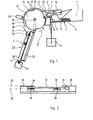
- the dispenser comprises a reservoir 1, the bottom 2 of which is inclined towards its outlet end 3.
- the spokes 4 are arranged horizontally in the reservoir 1, and represented according to their cross section in FIG. 1. Their two ends are guided by the lateral flanks of the tank 1, these lateral flanks being able to be at an adjustable distance from one another to adapt to radii of different lengths.
- a fixed stop 5 causes the thickness of the spoke layer to be reduced, so as to reduce the number of spokes occurring simultaneously in the vicinity of the end 3.
- the reservoir 1 is limited at its outlet end 3 by a knife 6, comprising a horizontal upper end 7 of thinned section, and driven by a vertical reciprocating translational movement, under the action of drive means 8.
- the knife 6 is movable between a first position, shown in dotted lines in FIG. 1, in which its upper end 7 is flush with the bottom 2 of the reservoir 1, and a second position, shown in solid lines, in which the upper end 7 is raised and flush with an inclined ramp 9 on which the spoke slides and abuts against a rotary drum 10 of substantially horizontal axis
- the drum 10 has longitudinal peripheral grooves 11 of section greater than the section of the spoke rod.
- the drum 10 driven in rotation in the direction represented by the arrow 12, drives the spokes inserted in the grooves 11.
- each groove is preceded by a flat 13, so that the front lip 14 of the groove is slightly lower than the lip 15 of this same groove.
- This produces a fastening structure allowing the gradual approximation of the radius rod of the axis of rotation of the drum 10, and its insertion in the groove 11.
- the ramp 9 comes flush with the drum 10 slightly above the horizontal diameter passing through the axis of rotation of the drum 10.
- the present invention also provides means for avoid the insertion and the catching of several spokes on the drum in the case where several spokes are driven by the knife 60
- a first fixed stop 16 disposed above the ramp 9 and the knife 6, at a distance slightly greater than the diameter of the spoke, defines an introduction corridor avoiding the overlapping of the spokes.
- the spout 17 of this stop 16 presses the spokes and optionally causes them to rotate against the cylinder and lets through only the spokes inserted in a groove 11.
- a second fixed stop 18, or scraper, disposed above the first, has a end positioned in abutment on the surface of the drum 10, to ensure that the spoke driven by the drum is properly inserted over its entire length in the groove 11 and to drop a second driven ray if necessary with the first spoke inserted in the groove.
- a cylindrical cover 19 covers the upper part of the drum 10, between the second stop 18 and the opposite drop of the drum, to maintain the spokes in the grooves throughout their journey. After the end 20 of the cover, the spokes fall on slides 21 bringing them onto a guide device 220
- a detector 23 is placed in the vicinity of the end 20 of the cover 19, this detector controlling the stopping of the knife 6 and of the drum 10 when a spoke is present in a groove 11 opposite the detector 23.
- the movement of the drum 10 and the knife 6 is again launched as soon as a radius expulsion order is given to the device by the control members of the beaming machine.
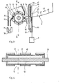
- the guide device 22 comprises two inclined and substantially parallel surfaces, arranged one opposite the other to allow the sliding of a spoke between them, a first surface 24, or upper surface, has a slippery and smooth lower face. to allow a ray to slide against it.
- a second surface 25, or lower surface has an upper face made of an adherent material, so that this second surface produces on the spoke a torque when it falls, as shown by arrow 26o
- the upper surface 24 has a width greater than the length of the spoke, so that the spoke head 27 comes to bear against this surface, while the lower surface 25 has a width less than the length of the spoke to allow free rotation of the head 27.
- the surfaces 24 and 25 may not be continuous, and constituted for example by disjoint inclined metal bands: the upper surface 24, in the embodiment shown, comprises two metal bands 28 and 29, arranged at the two ends of the spoke, and the lower surface 25 comprises two bands 30 and 31, a first band 30 being for example - ple disposed at a quarter of the length of the rod 32 of radius starting from the head 27 and the second strip 31 being arranged opposite strip 29 in the vicinity of the other end of the spoke.
- the strips 30 and 31 are covered with layers 33 and 34 of adhesive material such as rubber.
- the distance between the planes formed by the upper 24 and lower 25 surfaces is adjusted so as to allow the rotation of the rod 32 on the bands 30 and 31, the sliding of this rod on the upper band 29, and the sliding support of the head 27 against the strip 28.
- a distance between these two surfaces will preferably be chosen between the thickness of the rod 32 and the half sum of the diameters of the rod 32 and of the head 27.
- the spoke After sliding between the surfaces 24 and 25, the spoke falls into a chute 34 forming part of the radiating machine. To ensure correct positioning of the spoke in the chute, it is preferable to position the guide device 22 so that its lower end comes flush with the chute 34. In this case, it may be necessary to provide means for escaping the guide device 22 after insertion of a spoke into the chute 34, which can be achieved by providing to mount this guide device 22 on a rotary support, rotating for example around the axis 35 of the drum 10, and driven by drive means not shown in the figures.
- the following embodiment may be preferred, in which the selection means associated with the rotary drum have been modified.
- this second embodiment will be described in relation to a modified and simplified discharge ramp 22, which no longer ensures the systematic positioning of the ray head upwards at the outlet of the ramp.
- This simplified embodiment of the discharge ramp is suitable for use in which it is not necessary to fix the position of this spoke head. We can of course associate this simplified embodiment of the discharge ramp with the first embodiment of the selection means described above.
- FIGS. 3 and 4 This second embodiment is illustrated by FIGS. 3 and 4.
- the bottom 2 of the reservoir 1 comprises two successive flat parts 40 and 41 forming a re-entrant dihedral, as shown in FIG. 3, connected along a line 42 transverse to the direction 43 of ray progression.
- This arrangement favors the parallelism of the spokes and their transverse positioning in the tank. It can also be used in the embodiment of Figures 1 and 2. It is also possible to use a continuously curved bottom 2 defined by horizontal transverse generators, such as a portion of cylinder
- the selection device at the outlet 3 of the reservoir comprises a first knife 44, driven by a vertical reciprocating translational movement, under the action of drive means 8.
- the knife 44 is movable between a first position, shown in solid lines in the figure, in which the upper edge 45 is flush with the bottom 2 of the reservoir 1, and a second position, shown in dotted lines, in which the upper edge 45 reaches the level of an intermediate ramp 46 leading to a second knife 47.
- the second knife is driven by a vertical reciprocating translational movement in synchronism with the first knife. It is movable between a lower position, shown in solid lines in the figure, in which its upper edge is flush with the intermediate ramp 46, and an upper position in which its upper edge reaches the level of an upper ramp 48.
- the upper ramp 48 is connected to the guide ramp 9 by a jump. However, it is possible to provide ramps 9 and 48 on the same level. Tests have shown that the first knife 44 must have a large vertical reduction, for example of the order of half the length of the rod of a spoke, while the second knife can have a lower clearance.
- the thickness of the first knife is chosen so as to allow the insertion of one to three spokes on its upper edge. This thickness is substantially the same as the sum of the thicknesses of the second knife and of the intermediate ramp 46 0
- the second knife has a reduced thickness, so as to take only one radius at a time.
- the rotary drum 10, driven in rotation about the transverse axis 35-by a drive motor not shown in the figure, has a substantially cylindrical outer surface cut by longitudinal peripheral grooves 11, parallel to the axis 35, of section sufficient to admit the rod of a spoke.
- Magnets 49 are arranged in the bottom of the grooves 11, which promote the drive of only one spoke at a time and press the rod in the bottom of the groove throughout its transport by the drum.
- a scraper 50 is disposed at the start of the upper part of the drum, as shown in the figure, near its outer surface.
- circular peripheral grooves 51 are formed on the drum, deeper than the grooves 11, and in which the upper ends 52 in the form of a comb of the ramp are housed. evacuation 220
- the discharge ramp 22 is simplified, and leads along a short path the spokes in a wide chute 34.
- the inclination of the spoke head relative to the rod does not matter in this device.
- the drive of the second knife 47 can be ensured by the first knife 44.
- the first knife is secured to a rod 53 coming to bear against the lower edge of the second knife and to lift it during the end of travel of the first knife.
- a stop 54 limits the stroke of the second knife towards the base Tests have shown that the height of the ramp 22 should be limited as much as possible to avoid bouncing of spokes and reducing their fall time
- a first detector 55 at the level of the guide ramp 9 for controlling the stopping of the knives when radius at least is present on this ramp.
- a second detector 56 is arranged downstream of the discharge ramp 22, for example at the level of the chute 34, and controls the stopping of the drum when a spoke is present in the chute.
Abstract
Le distributeur comprend un réservoir (1), un couteau (6) animé d'un mouvement de translation alternatif vertical, une rampe inclinée (9) amenant les rayons en butée contre un tambour (10) muni de rainures périphériques (11). La rotation du tambour (10) amène les rayons un à un dans un dispositif de guidage (22) comprenant deux surfaces inclinées (24, 25), la surface supérieure (24) étant glissante, et la surface inférieure (25) étant en matière adhérente.The dispenser comprises a reservoir (1), a knife (6) driven by a vertical reciprocating translational movement, an inclined ramp (9) bringing the spokes into abutment against a drum (10) provided with peripheral grooves (11). The rotation of the drum (10) brings the spokes one by one into a guide device (22) comprising two inclined surfaces (24, 25), the upper surface (24) being sliding, and the lower surface (25) being made of material. adherent.
Application à la réalisation de distributeurs pour l'insertion automatique de rayons dans une machine pour insérer des rayons dans les trous de moyeux de roues à rayons.
Description
La présente invention concerne un dispositif pour amener de façon automatique les rayons un à un à partir d'un réservoir jusqu'à une machine permettant d'introduire les rayons dans les trous d'un moyeu de roue à rayons.The present invention relates to a device for automatically feeding the spokes one by one from a reservoir to a machine making it possible to introduce the spokes into the holes of a spoke wheel hub.
L'enfilage des rayons dans les moyeux de roues à rayons est une opération minutieuse et délicate qui jusqu'alors a été effectuée de façon manuelle. Des machines sont en cours de développement pour permettre d'effectuer cet enfilage de façon automatiqueo Il est alors nécessaire d'alimenter ces dispositifs en rayons, ces rayons étant disposés dans une position déterminée. En effet, les rayons comprennent généralement une tige rectiligne cylindrique, dont une extrémité est recourbée et comporte une tête de diamètre plus important. Pour effec- tier un enfilage correct, certains dispositifs nécessitent que la tête soit positionnée selon une direction déterminée, d'une part pour permettre le passage du rayon dans la machine à rayonner, et d'autre part pour assurer un bon positionnement du rayon sur le moyeu de roue à rayonsoThreading the spokes into the spoked wheel hubs is a meticulous and delicate operation which has hitherto been carried out manually. Machines are being developed to allow this threading to be carried out automatically. It is then necessary to supply these devices with spokes, these spokes being arranged in a determined position. Indeed, the spokes generally comprise a straight cylindrical rod, one end of which is curved and has a head of larger diameter. To carry out a correct threading, certain devices require that the head be positioned in a determined direction, on the one hand to allow the passage of the ray in the radiating machine, and on the other hand to ensure a good positioning of the ray on the spoke wheel hub
0n a déjà réalisé des distributeurs pour pièces diverses. Ainsi le brevet US 3 080 092 décrit un distributeur pour vis comportant un sélecteur à couteau, suivi d'une rampe en glissière à section spéciale, les vis passant sous un rouleau muni de gorges périphériques circulaires dans lesquelles s'engagent les vis lorsqu'elles sont en bonne position. Dans ce dispositif le rouleau fait seulement office de butée, et ne peut convenir pour la sélection de rayonsoWe have already produced distributors for various parts. Thus, US Pat. No. 3,080,092 describes a distributor for screws comprising a knife selector, followed by a slide rail with a special section, the screws passing under a roller provided with circular peripheral grooves in which the screws engage when they are in a good position. In this device the roller acts only as a stop, and cannot be suitable for the selection of rays
Le brevet US 2 823 830 décrit des moyens pour amener en bonne position des vis par un convoyeur rotatif disposé entre deux canalisationso Ce dispositif n'assure pas une véritable sélection et est inapplicable à la forme des rayonsoUS Patent 2,823,830 describes means for bringing the screws into good position by a rotary conveyor disposed between two pipes. This device does not ensure true selection and is inapplicable to the shape of the spokes.
Un objet de la présente invention est de proposer un distributeur de rayons permettant de présenter de façon automatique les rayons un à un et de les amener dans une position prédéterminée dans la machine à rayonner. Dans un premier mode de réalisation décrit, la machine à rayonner comprend une goulotte sensiblement horizontale et dans laquelle doit être insérée la tige de rayon, la tête de rayon étant disposée en dessus de la goulotteo Ainsi, le dispositif doit amener les rayons dans une position sensiblement horizontale, par translation de haut en bas, la tête de rayon étant dirigée vers le haut.An object of the present invention is to provide a ray distributor making it possible to automatically present the rays one by one and bringing them to a predetermined position in the radiating machine. In a first embodiment described, the radiating machine comprises a substantially horizontal chute and into which the spoke rod must be inserted, the spoke head being disposed above the chute. Thus, the device must bringing the spokes into a substantially horizontal position, by translation from top to bottom, the spoke head being directed upwards.
Dans un second mode de réalisation, la goulotte est plus large et il suffit que le rayon soit dans le bon sens, quelque soit l'inclinaison de la tête.In a second embodiment, the chute is wider and it suffices that the radius is in the right direction, whatever the inclination of the head.
Un autre objet de la présente invention est de proposer un distributeur permettant déviter la présentation de deux rayons à la fois, bien que la forme des rayons avec une tête recourbée ait tendance à provoquer leur crochage et leur entraînement simultanéeAnother object of the present invention is to provide a dispenser making it possible to avoid the presentation of two rays at the same time, although the shape of the rays with a curved head tends to cause them to spit out and their simultaneous training.
Un autre objet de l'invention est de proposer un distributeur évitant particulièrement le coincement des rayons et le blocage du dispositifoAnother object of the invention is to provide a dispenser which particularly avoids jamming the spokes and blocking the device.
Selon un autre objet de l'invention, les rayons sont présentés en un temps très court, de façon à limiter les temps morts et augmenter la cadence de la machine à rayonneroAccording to another object of the invention, the spokes are presented in a very short time, so as to limit the dead times and increase the rate of the rayonnero machine
Pour ce faire, et selon une caractéristique de l'invention, le distributeur comprend un réservoir à rayons dans lequel les rayons sont disposés en position horizontale, un dispositif à couteaux permettant de sélectionner les rayons et les amener un à un depuis le réservoir jusqu'à une rampe de guidage descendante ; un tambour est entrainé en rotation selon un axe transversal ; il est muni de rainures périphériques parallèles à son axe et de section supérieure à la section des tiges de rayon. Le tambour est disposé en aval de la rampe de guidage pour recevoir les rayons dans ses rainures, et est associé à des butées fixes telles qu'un racleur ; ainsi la rotation du tambour assure simultanément la sélection des rayons, leur stockage intermédiaire en file d'attente disjointe, et leur transport depuis la rampe de guidage jusqu'à une rampe d'évacuation.To do this, and according to a characteristic of the invention, the dispenser comprises a spoke reservoir in which the spokes are arranged in a horizontal position, a knife device making it possible to select the spokes and bring them one by one from the reservoir to a descending guide ramp; a drum is rotated along a transverse axis; it is provided with peripheral grooves parallel to its axis and of section greater than the section of the spoke rods. The drum is arranged downstream of the guide ramp to receive the spokes in its grooves, and is associated with fixed stops such as a scraper; thus the rotation of the drum simultaneously ensures the selection of the spokes, their intermediate storage in disjoined queue, and their transport from the guide ramp to a discharge ramp.
Selon une autre caractéristique de l'invention, le dispositif de guidage comprend deux surfaces inclinées sensiblement parallèles, disposées l'une en face de l'autre à une distance prédéterminée pour permettre le glissement d'un rayon entre elles, la première surface ou surface supérieure étant glissante, la seconde surface ou surface inférieure étant en une matière adhérente pour produire sur le rayon un couple de rotation lors de son glissement, la première surface bloquant alors la rotation de la tête pour la maintenir au-dessus de la tige.According to another characteristic of the invention, the guide device comprises two substantially parallel inclined surfaces, arranged one opposite the other at a predetermined distance to allow the sliding of a ray between them, the first surface or surface upper being slippery, the second surface or lower surface being of an adherent material to produce on the spoke a torque when it slides, the first surface then blocking the rotation of the head for the hand stand above the rod.
Selon une autre caractéristique de l'invention, la première surface a une largeur au moins égale à la longueur du rayon, de sorte que la tête de rayon vienne en appui glissant contre elle, la seconde surface ayant une largeur inférieure pour libérer la tête de rayon ; la distance entre les deux surfaces est supérieure au diamètre de la tige de rayon et inférieure à la demi somme du diamètre de la tige et du diamètre de la tête de rayon. On réalise ainsi un dispositif de guidage assurant le maximum de liberté au rayon, tout en interdisant sa rotation et en maintenant la tête de rayon au-dessus de la tige. Les blocages et coincements des rayons sont ainsi considérablement réduits.According to another characteristic of the invention, the first surface has a width at least equal to the length of the spoke, so that the spoke head comes to bear slidingly against it, the second surface having a smaller width to release the head from Ray ; the distance between the two surfaces is greater than the diameter of the spoke rod and less than half the sum of the diameter of the rod and the diameter of the spoke head. This produces a guide device ensuring maximum freedom to the spoke, while preventing its rotation and keeping the head of the spoke above the rod. The blockages and jams of the spokes are thus considerably reduced.
Selon une autre disposition, le dispositif de sélection à couteau comprend deux couteaux consécutifs, un premier couteau à grand débattement, suivi d'un second couteau à débattement plus faible mais de position plus élevéeAccording to another arrangement, the knife selection device comprises two consecutive knives, a first knife with a large clearance, followed by a second knife with a lower clearance but with a higher position.
Selon une autre caractéristique de l'invention, on dispose un détecteur pour détecter la présence d'un rayon dans la zone supérieure du cylindre et commander l'arrêt du cylindre et du couteau jusqu'à réception d'un ordre d'éjection d'un rayon dans la machine à rayonnero Ainsi, le dispositif sélectionne librement les rayons dans le réservoir jusqu'à ce qu'un rayon soit présenté prêt à être éjecté, le dispositif étant alors maintenu en état d'attente. On réduit ainsi les temps de transit des rayons, sans subir les retards éventuels dûs au fait que l'enchevêtrement des rayons dans le réservoir ne permet pas au couteau de séparer un rayon à chaque mouvement.According to another characteristic of the invention, there is a detector for detecting the presence of a ray in the upper zone of the cylinder and controlling the stopping of the cylinder and of the knife until receipt of an ejection order from a department in the shelving machine Thus, the device freely selects the departments in the tank until a department is presented ready to be ejected, the device then being kept in the waiting state. This reduces the transit times of the spokes, without suffering any delays due to the fact that the tangle of spokes in the tank does not allow the knife to separate a spoke with each movement.
D'autres caractéristiques et avantages de la présente invention ressortiront de la description suivante de modesde réalisation particuliers, faite en relation avec les figures jointes parmi lesquelles :
- - la figure 1 représente une vue schématique en coupe longitudinale du distributeur selon la présente invention dans un premier mode de réalisation ;
- - la figure 2 représente une vue en coupe partielle selon l'axe I-I de la figure 1 ;
- - la figure 3 représente une vue en coupe longitudinale d'un distributeur selon un second mode de réalisation ; et
- - la figure 4 représente une vue en coupe transversale selon l'axe II-II de la figure 3.
- - Figure 1 shows a schematic view in longitudinal section of the dispenser according to the present invention in a first embodiment;
- - Figure 2 shows a partial sectional view along the axis II of Figure 1;
- - Figure 3 shows a longitudinal sectional view of a dispenser according to a second embodiment; and
- - Figure 4 shows a cross-sectional view along the axis II-II of Figure 3.
Comme le représentent les figures 1 et 2, le distributeur comprend un réservoir 1 dont le fond 2 est incliné vers son extrémité de sortie 3. Les rayons 4 sont disposés horizontalement dans le réservoir 1, et représentés selon leur section transversale sur la figure 1. Leurs deux extrémités sont guidées par les flancs latéraux du réservoir 1, ces flancs latéraux pouvant être à une distance réglable l'un de l'autre pour s'adapter à des rayons de longueurs différentes. Au voisinage de l'extrémité de sortie 3, une butée fixe 5 provoque la réduction d'épaisseur de la couche de rayons, de façon à diminuer le nombre de rayons se présentant simultanément au voisinage de l'extrémité 3.As shown in FIGS. 1 and 2, the dispenser comprises a reservoir 1, the
Le réservoir 1 est limité à son extrémité de sortie 3 par un couteau 6, comportant une extrémité supérieure horizontale 7 de section amincie, et animé d'un mouvement de translation alternatif vertical, sous l'action de moyens d'entraînement 8. Le couteau 6 est mobile entre une première position, représentée en pointillés sur la figure 1, dans laquelle son extrémité supérieure 7 est en affleurement du fond 2 du réservoir 1, et une seconde position, représentée en traits pleins, dans laquelle l'extrémité supérieure 7 est surélevée et vient en affleurement d'une rampe inclinée 9 sur laquelle le rayon glisse et vientbuter contre un tambour rotatif 10 d'axe sensiblement horizontaleThe reservoir 1 is limited at its
Le tambour 10 comporte des rainures périphériques longitudinales 11 de section supérieure à la section de la tige des rayons Le tambour 10, entraîné en rotation dans le sens représenté par la flèche 12, entraîne les rayons insérés dans les rainures 11. Pour assurer une bonne insertion des rayons dans les rainures, chaque rainure est précédée d'un méplat 13, de sorte que la lèvre antérieure 14 de la rainure est légèrement moins haute que la lèvre 15 de cette même rainure. On réalise ainsi une structure d'accrochage permettant le rapprochement progressif de la tige de rayon de l'axe de rotation du tambour 10, et son insertion dans la rainure 11. Comme le représente la figure 1, la rampe 9 vient à affleurement du tambour 10 légèrement au-dessus du diamètre horizontal passant par l'axe de rotation du tambour 10.The
Ia présente invention prévoit également des moyens pour éviter l'insertion et l'accrochage de plusieurs rayons sur le tambour dans le cas où plusieurs rayons sont entraînés par le couteau 60 Ainsi, une première butée fixe 16, disposée au-dessus de la rampe 9 et du couteau 6, à une distance légèrement supérieure au diamètre de la tige de rayon, définit un couloir d'introduction évitant le chevauchement des rayons. Le bec 17 de cette butée 16 plaque les rayons et provoque éventuellement leur rotation contre le cylindre et ne laisse passer que les rayons insérés dans une rainure 11. Une seconde butée fixe 18, ou racleur, disposée au-dessus de la première, a une extrémité positionnée en appui sur la surface du tambour 10, pour s'assurer que le rayon entraîné par le tambour est bien inséré sur toute sa longueur dans la rainure 11 et faire tomber un second rayon entraîné le cas échéant avec le premier rayon inséré dans la rainure.The present invention also provides means for avoid the insertion and the catching of several spokes on the drum in the case where several spokes are driven by the knife 60 Thus, a first fixed
Un capot cylindrique 19 recouvre la partie supérieure du tambour 10, entre la seconde butée 18 et la retombée opposée du tambour, pour maintenir les rayons dans les rainures pendant tout leur parcours. Après l'extrémité 20 du capot, les rayons tombent sur des glissières 21 les amenant sur un dispositif de guidage 220A
Entre l'extrémité 20 du capot et le réservoir 1, le trajet des rayons est relativement grand, d'autant que le couteau 6 ne sépare pas un rayon à chaque mouvement. Pour limiter les temps de transit et augmenter la rapidité du dispositif, on place un détecteur 23 au voisinage de l'extrémité 20 du capot 19, ce détecteur commandant l'arrêt du couteau 6 et du tambour 10 lorsqu'un rayon est présent dans une rainure 11 en regard du détecteur 23. Le mouvement du tambour 10 et du couteau 6 est à nouveau lancé dès qu'un ordre d'expulsion de rayon est donné au dispositif par les organes de commande de la machine à rayonner.Between the
Le dispositif de guidage 22 comprend deux surfaces inclinées et sensiblement parallèles, disposées l'une en face de l'autre pour permettre le glissement d'un rayon entre elles, une première surface 24, ou surface supérieure, comporte une face inférieure glissante et lisse pour permettre le glissement d'un rayon contre elle. Une seconde surface 25, ou surface inférieure, comporte une face supérieure en une matière adhérente, de sorte que cette seconde surface produit sur le rayon un couple de rotation lors de sa chute, comme le représente la flèche 26o La surface supérieure 24 a une largeur supérieure à la longueur du rayon, de sorte que la tête de rayon 27 vienne en appui contre cette surface, tandis que la surface inférieure 25 a une largeur inférieure à la longueur du rayon pour permettre la libre rotation de la tête 27.The
Comme le représente en coupe la figure 2, les surfaces 24 et 25 peuvent ne pas être continues, et constituées par exemple de bandes métalliques inclinées disjointes : la surface supérieure 24, dans le mode de réalisation représenté, comprend deux bandes 28 et 29 métalliques, disposées aux deux extrémités du rayon, et la surface inférieure 25 comprend deux bandes 30 et 31, une première bande 30 étant par exem- - ple disposée au quart de la longueur de la tige 32 de rayon en partant de la tête 27 et la seconde bande 31 étant disposée en regard de la bande 29 au voisinage de l'autre extrémité du rayon. Les bandes 30 et 31 sont recouvertes de couches 33 et 34 de matière adhérente telle que du caoutchouc. La distance entre les plans formés par les surfaces supérieure 24 et inférieure 25 est réglée de façon à permettre la rotation de la tige 32 sur les bandes 30 et 31, le glissement de cette tige sur la bande supérieure 29, et l'appui glissant de la tête 27 contre la bande 28. Pour cela, on choisira de préférence une distance entre ces deux surfaces comprise entre l'épaisseur de la tige 32 et la demi somme des diamètres de la tige 32 et de la tête 27.As shown in section in FIG. 2, the
Après glissement entre les surfaces 24 et 25, le rayon tombe dans une goulotte 34 faisant partie de la machine à rayonner. Pour assurer un bon positionnement du rayon dans la goulotte, il est préférable de positionner le dispositif de guidage 22 de façon que son extrémité inférieure vienne en affleurement de la goulotte 34. Dans ce cas, il peut être nécessaire de prévoir des moyens pour faire échapper le dispositif de guidage 22 après insertion d'un rayon dans la goulotte 34, ce qui peut être réalisé en prévoyant de monter ce dispositif de guidage 22 sur un support rotatif, tournant par exemple autour de l'axe 35 du tambour 10, et entraîné par des moyens d'entraînement non représentés sur les figures.After sliding between the
Le mode de réalisation qui vient d'être décrit assure une bonne sélection des rayons et leur positionnement tête en haut en sortie de la rampe d'évacuation 220 La forme particulière des rayons rend leur sélection délicate, et le dispositif est bien adapté à cette forme. Toutefois certaines erreurs de sélection ont encore pu être constatées lors des nombreux essais auxquels le demandeur a procédé.The embodiment which has just been described ensures good selection of the spokes and their head-up positioning at the outlet of the evacuation ramp 220 The particular shape of the spokes makes their selection difficult, and the device is well suited to this shape. However, certain selection errors could still be noted during the numerous tests carried out by the applicant.
Pour réduire le nombre d'erreurs de sélection, et améliorer la fiabilité du dispositif, on pourra préférer le mode de réalisation suivant, dans lequel les moyens de sélection associés au tambour rotatif ont été modifiés. En outre, ce second mode de réalisation sera décrit en relation avec une rampe d'évacuation 22 modifiée et simplifiée, qui n'assure plus le positionnement systématique de la tête de rayon vers le haut en sortie de la rampe. Cette réalisation simplifiée de la rampe d'évacuation convient à une utilisation dans laquelle il n'est pas nécessaire de fixer la position de cette tête de rayon. On pourra bien entendu associer ce mode de réalisation simplifié de la rampe d'évacuation avec le premier mode de réalisation des moyens de sélection précédemment décrits.To reduce the number of selection errors, and improve the reliability of the device, the following embodiment may be preferred, in which the selection means associated with the rotary drum have been modified. In addition, this second embodiment will be described in relation to a modified and
Ce second mode de réalisation est illustré par les figures 3 et 4. Le fond 2 du réservoir 1 comprend deux parties planes successives 40 et 41 formant un dièdre rentrant, comme le représente la figure 3, raccordées selon une ligne 42 transversale par rapport à la direction 43 de progression des rayons. Cette disposition favorise le parallélisme des rayons et leur positionnement transversal dans le réservoir. Elle peut être également utilisée dans le mode de réalisation des figures 1 et 2. On pourra également utiliser un fond 2 incurvé de façon continue défini par des génératrices transversales horizontales, tel qu'une portion de cylindreThis second embodiment is illustrated by FIGS. 3 and 4. The
Le dispositif de sélection en sortie 3 du réservoir comprend un premier couteau 44, animé d'un mouvement de translation alternatif vertical, sous l'action de moyens d'entraînement 8. Le couteau 44 est mobile entre une première position, représentée en traits pleins sur la figure, dans laquelle la tranche supérieure 45 affleure le fond 2 du réservoir 1, et une seconde position, représentée en pointillés, dans laquelle la tranche supérieure 45 atteint le niveau d'une rampe intermédiaire 46 conduisant à un second couteau 47. Le second couteau est animé d'un mouvement de translation alternatif vertical en synchronisme avec le premier couteauo Il est mobile entre une position inférieure, représentée en traits pleins sur la figure, dans laquelle sa tranche supérieure affleure la rampe intermédiaire 46, et une position supérieure dans laquelle sa tranche supérieure atteint le niveau d'une rampe supérieure 48. La rampe supérieure 48 se raccorde à la rampe de guidage 9 par un saut. On pourra toutefois prévoir des rampes 9 et 48 sur le même niveau. Les essais ont montré que le premier couteau 44 doit avoir un abattement vertical important, par exemple de l'ordre de la demi longueur de tige d'un rayon, tandis que le second couteau peut avoir un débattement plus faible. L'épaisseur du premier couteau est choisie de façon à permettre l'insertion de un à trois rayons sur sa tranche supérieure. Cette épaisseur est sensiblement la même que la somme des épaisseurs du second couteau et de la rampe intermédiaire 460 Le second couteau a une épaisseur réduite, de façon à ne prendre qu'un seul rayon à la fois.The selection device at the
Le tambour rotatif 10, entraîné en rotation autour de l'axe transversal 35-par un moteur d'entraînement non représenté sur la figure, comporte une surface extérieure sensiblement cylindrique découpée par des rainures périphériques longitudinales 11, parallèles à l'axe 35, de section suffisante pour admettre la tige d'un rayon. Des aimants 49 sont disposés dans le fond des rainures 11, qui favorisent l'entraînement d'un seul rayon à la fois et plaquent la tige dans le fond de rainure tout au long de son transport par le tambour. Un racleur 50 est disposé au début de la partie supérieure du tambour, comme le représente la figure, au voisinage de sa surface extérieure.The
Pour décoller les rayons et les éjecter sur la rampe d'évacuation 22, on ménage sur le tambour des gorges périphériques circulaires 51, plus profondes que les rainures 11, et dans lesquelles viennent se loger les extrémités supérieures 52 en forme de peigne de la rampe d'évacuation 220To unstick the spokes and eject them on the
Dans ce mode de réalisation, la rampe d'évacuation 22 est simplifiée, et conduit selon un trajet court les rayons dans une goulotte 34 large. L'inclinaison de la tête de rayon par rapport à la tige n'a pas d'importance dans ce dispositif.In this embodiment, the
L'entraînement du second couteau 47 peut être assuré par le premier couteau 44. A cet effet le premier couteau est solidaire d'une tige 53 venant porter contre la tranche inférieure du second couteau et le soulever pendant la fin de course du premier couteau. Une butée 54 limite la course du second couteau vers le base Les essais ont montré qu'il convient de limiter autant que possible la hauteur de la rampe 22 pour éviter les rebonds de rayons et diminuer leur temps de chuteThe drive of the
Selon un mode de réalisation particulier, qui augmente la certitude de présence d'un rayon pour son éjection rapide sur la rampe 22, on dispose un premier détecteur 55 au niveau de la rampe de guidage 9 pour commander l'arrêt des couteaux lorsqu'un rayon au moins est présent sur cette rampe. Un second détecteur 56 est disposé en aval de la rampe d'évacuation 22, par exemple au niveau de la goulotte 34, et commande l'arrêt du tambour lorsqu'un rayon est présent dans la goulotte.According to a particular embodiment, which increases the certainty of the presence of a spoke for its rapid ejection on the
Dans le cas d'une utilisation en relation avec une machine à rayonner comportant un chariot pousseur pour éjecter le rayon de la goulotte 34, il pourra être nécessaire de prévoir un troisième détecteur pour détecter que le chariot est en bonne position et permettre l'introduction d'un nouveau rayon dans la goulotte. Ce troisième détecteur commande la remise en rotation du tambouroIn the case of use in connection with a radiating machine comprising a pusher carriage for ejecting the ray from the
La présente invention n'est pas limitée aux modes de réalisation qui ont été explicitement décrits, mais elle inclut les diverses variantes et généralisations contenues dans le domaine des revendications ci-aprèsoThe present invention is not limited to the embodiments which have been explicitly described, but it includes the various variants and generalizations contained in the field of claims below.
Claims (10)
Applications Claiming Priority (2)
| Application Number | Priority Date | Filing Date | Title |
|---|---|---|---|
| FR8115318A FR2510451A1 (en) | 1981-08-03 | 1981-08-03 | WHEEL RAY DISTRIBUTOR WITH RAYS FOR A RADIANT MACHINE |
| FR8115318 | 1981-08-03 |
Publications (1)
| Publication Number | Publication Date |
|---|---|
| EP0071856A1 true EP0071856A1 (en) | 1983-02-16 |
Family
ID=9261270
Family Applications (1)
| Application Number | Title | Priority Date | Filing Date |
|---|---|---|---|
| EP82106717A Withdrawn EP0071856A1 (en) | 1981-08-03 | 1982-07-26 | Wire distributor for a wheel assembling machine |
Country Status (4)
| Country | Link |
|---|---|
| US (1) | US4511058A (en) |
| EP (1) | EP0071856A1 (en) |
| JP (1) | JPS5830803A (en) |
| FR (1) | FR2510451A1 (en) |
Cited By (4)
| Publication number | Priority date | Publication date | Assignee | Title |
|---|---|---|---|---|
| US4927054A (en) * | 1988-01-30 | 1990-05-22 | Sussman, Jennewein Bekleidungstechnik Gmbh | Apparatus for singularizing garment hangers |
| US5097938A (en) * | 1988-03-08 | 1992-03-24 | Boehringer Mannheim Gmbh | Apparatus for transferring test strips to an examining apparatus |
| WO1995003184A1 (en) * | 1993-07-20 | 1995-02-02 | Machibo B.V. | Wheel-lacing apparatus for mounting spokes between the hub and the rim of a spoke wheel, and method of using same |
| WO2023017216A1 (en) | 2021-08-13 | 2023-02-16 | Bikebotix | Device for supplying spokes from a spoke-ejecting gun into holes in a hub of a spoked wheel |
Families Citing this family (9)
| Publication number | Priority date | Publication date | Assignee | Title |
|---|---|---|---|---|
| US4721228A (en) * | 1985-04-03 | 1988-01-26 | Itt Corporation | Apparatus for dispensing elongated small mechanical parts |
| JPH07108601B2 (en) * | 1986-03-20 | 1995-11-22 | ブリヂストンサイクル株式会社 | Spoke wire feeder |
| JP2566167B2 (en) * | 1989-10-20 | 1996-12-25 | 新家工業株式会社 | Spoke guide device for spoke launch device |
| DE69209326T2 (en) * | 1991-01-12 | 1996-10-31 | Yoshitaka Aoyama | Parts feeder |
| US5402911A (en) * | 1994-04-22 | 1995-04-04 | Noell; Robert E. | Reconfigurable article dispenser |
| US6427867B1 (en) * | 1999-12-28 | 2002-08-06 | Thomas G. Frebes | Sewing pin dispensing device |
| US7149600B2 (en) * | 2003-10-08 | 2006-12-12 | Waterfall Inc. | Pipe storage and inventory control chest |
| JP5813183B1 (en) * | 2014-07-02 | 2015-11-17 | 株式会社大武ルート工業 | Screw supply mechanism of screw feeder |
| CN112975337B (en) * | 2021-02-21 | 2022-10-14 | 深圳精达宇科技有限公司 | Full-automatic equipment of razor tool bit |
Citations (7)
| Publication number | Priority date | Publication date | Assignee | Title |
|---|---|---|---|---|
| US2677452A (en) * | 1952-11-29 | 1954-05-04 | Pressed Steel Car Company Inc | Case inverter |
| US2823830A (en) * | 1951-06-05 | 1958-02-18 | Kreidler Alfred | Apparatus for feeding of pin-shaped bodies with a one-sided center of gravity |
| US2959270A (en) * | 1959-01-20 | 1960-11-08 | Continental Can Co | Can positioning machine |
| US3080092A (en) * | 1958-11-04 | 1963-03-05 | Siemon Co | Material feed apparatus |
| DE2027788A1 (en) * | 1969-06-06 | 1970-12-17 | Japan Bicycle Promotion Institute, Tokio | Device for pre-assembling wire spoke wheels |
| US3758931A (en) * | 1971-12-29 | 1973-09-18 | Huffman Manuf Co | Wheel assembly method and apparatus |
| US4062095A (en) * | 1976-08-03 | 1977-12-13 | Storz Edwin L | Automatic wire feeder |
Family Cites Families (10)
| Publication number | Priority date | Publication date | Assignee | Title |
|---|---|---|---|---|
| US14290A (en) * | 1856-02-19 | Michael phelan | ||
| GB245322A (en) * | 1925-02-10 | 1926-01-07 | Karl Fazer O Y Ab | Improvements in transporting and feeding mechanism |
| GB548707A (en) * | 1941-04-18 | 1942-10-21 | Dunlop Rubber Co | Improvements in chutes for feeding or conveying ammunition or other bodies |
| US2420812A (en) * | 1944-02-21 | 1947-05-20 | Frank A Brunner | Toothpick dispenser |
| US2696327A (en) * | 1949-07-16 | 1954-12-07 | Bauer Bros Co | Wire feeder |
| FR1017917A (en) * | 1950-05-13 | 1952-12-22 | Method and devices for sowing seeds | |
| US2743001A (en) * | 1954-12-10 | 1956-04-24 | American Can Co | Can divider |
| US2819465A (en) * | 1955-09-16 | 1958-01-14 | United Shoe Machinery Corp | Article handling mechanisms |
| US3115235A (en) * | 1962-10-29 | 1963-12-24 | Pacific Semiconductors Inc | Diode orienting apparatus |
| US3737072A (en) * | 1971-11-12 | 1973-06-05 | Westinghouse Electric Corp | Feeding device for cylindrical tubing |
-
1981
- 1981-08-03 FR FR8115318A patent/FR2510451A1/en active Granted
-
1982
- 1982-07-26 EP EP82106717A patent/EP0071856A1/en not_active Withdrawn
- 1982-07-28 US US06/402,745 patent/US4511058A/en not_active Expired - Fee Related
- 1982-08-02 JP JP57135053A patent/JPS5830803A/en active Pending
Patent Citations (7)
| Publication number | Priority date | Publication date | Assignee | Title |
|---|---|---|---|---|
| US2823830A (en) * | 1951-06-05 | 1958-02-18 | Kreidler Alfred | Apparatus for feeding of pin-shaped bodies with a one-sided center of gravity |
| US2677452A (en) * | 1952-11-29 | 1954-05-04 | Pressed Steel Car Company Inc | Case inverter |
| US3080092A (en) * | 1958-11-04 | 1963-03-05 | Siemon Co | Material feed apparatus |
| US2959270A (en) * | 1959-01-20 | 1960-11-08 | Continental Can Co | Can positioning machine |
| DE2027788A1 (en) * | 1969-06-06 | 1970-12-17 | Japan Bicycle Promotion Institute, Tokio | Device for pre-assembling wire spoke wheels |
| US3758931A (en) * | 1971-12-29 | 1973-09-18 | Huffman Manuf Co | Wheel assembly method and apparatus |
| US4062095A (en) * | 1976-08-03 | 1977-12-13 | Storz Edwin L | Automatic wire feeder |
Cited By (6)
| Publication number | Priority date | Publication date | Assignee | Title |
|---|---|---|---|---|
| US4927054A (en) * | 1988-01-30 | 1990-05-22 | Sussman, Jennewein Bekleidungstechnik Gmbh | Apparatus for singularizing garment hangers |
| US5097938A (en) * | 1988-03-08 | 1992-03-24 | Boehringer Mannheim Gmbh | Apparatus for transferring test strips to an examining apparatus |
| WO1995003184A1 (en) * | 1993-07-20 | 1995-02-02 | Machibo B.V. | Wheel-lacing apparatus for mounting spokes between the hub and the rim of a spoke wheel, and method of using same |
| NL9301275A (en) * | 1993-07-20 | 1995-02-16 | Machibo B V | Wheel braiding device for mounting spokes between the hub and the rim of a spoke wheel, and a method for applying it. |
| WO2023017216A1 (en) | 2021-08-13 | 2023-02-16 | Bikebotix | Device for supplying spokes from a spoke-ejecting gun into holes in a hub of a spoked wheel |
| FR3126103A1 (en) * | 2021-08-13 | 2023-02-17 | Bikebotix | Device for feeding spokes from a spoke ejector gun into holes in a hub of a spoked wheel |
Also Published As
| Publication number | Publication date |
|---|---|
| US4511058A (en) | 1985-04-16 |
| FR2510451B1 (en) | 1984-05-11 |
| JPS5830803A (en) | 1983-02-23 |
| FR2510451A1 (en) | 1983-02-04 |
Similar Documents
| Publication | Publication Date | Title |
|---|---|---|
| EP0071856A1 (en) | Wire distributor for a wheel assembling machine | |
| EP0593382B1 (en) | Method and device for continuously labelling articles such as fruit or vegetables | |
| FR2549455A1 (en) | METHOD AND APPARATUS FOR INDEXING SHEET MATERIAL | |
| EP0125175B1 (en) | Apparatus for cutting continuously manufactured cardboard tubes | |
| FR2509274A1 (en) | WINDING MACHINE FOR METAL STRIP | |
| EP0005671B1 (en) | Machine for folding drawings to a determined size | |
| BE1009744A4 (en) | Distribution unit automatic packaging material in sheet. | |
| FR2552745A1 (en) | METHOD AND APPARATUS FOR ATTACHING A WIRE TO A SPOOL | |
| EP0921074A1 (en) | Method and apparatus for collecting aligned articles by means of adhesive tapes | |
| EP0480822A1 (en) | Device for a quick distribution of plate-like objects in a bucket conveyor | |
| EP0031783A1 (en) | Machine for winding wire on spools | |
| EP1361030B1 (en) | Method for manufacturing boards made of hydraulic binder and production line for manufacturing such boards | |
| FR2609458A1 (en) | Machine for automatic de-stacking and conveying of components, such as, for example, sheet-metal blanks | |
| EP1315663B1 (en) | Installation and method for conditioning a sheet of moulding material | |
| FR2627763A1 (en) | Sheet feeder for photocopier - has pressure mechanism operating with fixed and moving friction rollers and fixed cylindrical stop | |
| EP0820930B1 (en) | Machine for strapping rolls of web material | |
| FR2497781A1 (en) | METHOD FOR CHANGING COILS AND CHUCKS OF WINDING MACHINES WITHOUT AXIS | |
| FR2686906A1 (en) | Method and device for removing the underwinding yarn from spindles on a continuous spinning or twisting (doubling) frame | |
| EP0048656A1 (en) | Device for a machine opening, transferring and cutting thermoplastic sleeves and placing the sections around containers | |
| EP0076819A1 (en) | Guillotine shearing machine comprising a device for holding and discharging cut sheet metal | |
| FR2488183A1 (en) | Appts. for cutting and stacking plastic straws with a bevelled end - comprising series of radial and oblique blades and high-speed stacking device | |
| EP0340065A1 (en) | Method and installation for piling sheets produced by a shear, particularly from a sheet-metal-strip | |
| FR2581223A1 (en) | Method and installation for packaging stacks of coins | |
| FR2625946A1 (en) | INSTALLATION FOR MANUFACTURING AND STACKING BAGS, BAGS, ETC. IN THERMOPLASTIC MATTER | |
| FR2511636A1 (en) | Cutter for moving wood sheet - has moving blade controlled by fault detector working with cutting cylinder and drive |
Legal Events
| Date | Code | Title | Description |
|---|---|---|---|
| PUAI | Public reference made under article 153(3) epc to a published international application that has entered the european phase |
Free format text: ORIGINAL CODE: 0009012 |
|
| AK | Designated contracting states |
Designated state(s): AT BE CH DE FR GB IT LI LU NL SE |
|
| 17P | Request for examination filed |
Effective date: 19830808 |
|
| STAA | Information on the status of an ep patent application or granted ep patent |
Free format text: STATUS: THE APPLICATION HAS BEEN WITHDRAWN |
|
| 18W | Application withdrawn |
Withdrawal date: 19850401 |
|
| RIN1 | Information on inventor provided before grant (corrected) |
Inventor name: CARMINATI, JULIEN |