EP0071669B1 - Vorrichtung zur Überbrückung von Dehnungsfugen in Gehwegen, Parkdecks od. dgl. - Google Patents
Vorrichtung zur Überbrückung von Dehnungsfugen in Gehwegen, Parkdecks od. dgl. Download PDFInfo
- Publication number
- EP0071669B1 EP0071669B1 EP81106812A EP81106812A EP0071669B1 EP 0071669 B1 EP0071669 B1 EP 0071669B1 EP 81106812 A EP81106812 A EP 81106812A EP 81106812 A EP81106812 A EP 81106812A EP 0071669 B1 EP0071669 B1 EP 0071669B1
- Authority
- EP
- European Patent Office
- Prior art keywords
- joint
- thickening
- cavities
- profile
- faces
- Prior art date
- Legal status (The legal status is an assumption and is not a legal conclusion. Google has not performed a legal analysis and makes no representation as to the accuracy of the status listed.)
- Expired
Links
Images

Classifications
-
- E—FIXED CONSTRUCTIONS
- E01—CONSTRUCTION OF ROADS, RAILWAYS, OR BRIDGES
- E01C—CONSTRUCTION OF, OR SURFACES FOR, ROADS, SPORTS GROUNDS, OR THE LIKE; MACHINES OR AUXILIARY TOOLS FOR CONSTRUCTION OR REPAIR
- E01C11/00—Details of pavings
- E01C11/02—Arrangement or construction of joints; Methods of making joints; Packing for joints
- E01C11/04—Arrangement or construction of joints; Methods of making joints; Packing for joints for cement concrete paving
- E01C11/12—Packing of metal and plastic or elastic materials
- E01C11/126—Joints with only metal and prefabricated packing or filling
-
- E—FIXED CONSTRUCTIONS
- E01—CONSTRUCTION OF ROADS, RAILWAYS, OR BRIDGES
- E01D—CONSTRUCTION OF BRIDGES, ELEVATED ROADWAYS OR VIADUCTS; ASSEMBLY OF BRIDGES
- E01D19/00—Structural or constructional details of bridges
- E01D19/06—Arrangement, construction or bridging of expansion joints
Definitions
- the invention relates to a device for bridging expansion joints in sidewalks, parking decks or the like, with a sealing tape bridging the joint made of resiliently elastic material, which on opposite sides has pressed in open cavities of the joint edges, thickening extending in the direction of the tape which support surfaces, each pointing towards the joint, bear against corresponding inner surfaces of the cavities and are formed on the side facing away from the joint with a bead, which are bent back toward the joint in the installed position in order to close the thickenings in the interior of the associated cavity wedge.
- a known device of this type (German patent specification 2808386) has a sealing profile strip that cannot be walked on or driven over, so its use is limited to very narrow joints.
- the present invention has for its object to provide a limited traffic load-resistant joint seal that can be easily but securely anchored in corresponding cavities of the joint edges and also dismantled again.
- sealing tape is divided into two in the region of each thickening, the webs being molded onto one of the thickening parts, so that the bead is wedged between the thickening parts and thus keeps the support surfaces in their contact.
- the support surfaces and accordingly the inner surfaces of the cavities of the joint edges are inclined outside.
- such a sealing tape designed as a hollow profile has an outer and an inner profile ceiling, which are connected via ribs, the outer profile ceiling being flush with the roadway.
- the sealing tape can therefore be walked on or driven over in the region of the hollow profile.
- the invention provides for the inner profile ceiling to bulge out against the depth of the joint. The effect achieved in this way can be further improved if some ribs run approximately parallel to the plane of the joint gap, others in between diagonally from the top center down to the outside.
- the diagonally running ribs stabilize the hollow profile of the sealing tape located between the joint edges in the sense that the surface of the sealing tape adjacent to the traffic area is completely flat in every joint position, i.e. also when the joint edges are moved together.
- the ribs improve the removal of the vertical loads towards the joint edge.
- the profile ceilings form approximately right angles with the supporting surfaces. This means that, depending on the thickness of the hollow profile, the two profile ceilings converge laterally at an angle, the support surfaces, as already stated above, being inclined obliquely outwards from the middle of the joint.
- the joint edges which have inclined claws adjacent to the opening of the cavities, are formed accordingly.
- the inner claw is designed to support the inner profile ceiling widened accordingly.
- the sealing tape according to the invention enables a limited tensile strength, watertight connection to the joint edges, whereby it is of course essential that the size of the thickening parts and bead are adapted to the cross-sectional shape of the associated joint-side cavity. The same applies to the length of the web between the associated thickening part and bead. This is the only way to meet the requirement for easy assembly with the Forde together for a tight and tight fit.
- the lateral edges of the sealing tape each have a thickening divided into two parts, consisting of an outer thickening part 10 and an inner thickening part 11. Both thickening parts 10, 11 have supporting surfaces 12 which are approximately perpendicular to the adjoining profile ceilings and which on corresponding inner surfaces 13 of the joint edge profiles 7 are supported in the installed state of the sealing tape (see FIG. 2).
- the outer thickening part 10 each has a web 14 attached to it with a bead 15 at the end of the web.
- the web 14 can, as shown in FIG. 1, be bent back from the outset towards the middle of the joint on the thickening part 10; in a variant not shown, however, it can also be formed in a stretched manner to the side and can only be bent back inwards in the course of assembly.
- the inner thickening part 11 is made more solid than the outer thickening part 10.
- the inner thickening part 11 has a pressing surface 16 towards the outer thickening part 10. Between this pressing surface 16 and the opposite inner side 17 of the outer profile cover 2, the bead 15 in the region shown in and 3 shown wedged installation state of the sealing tape. On the right side of Fig. 2, the connection of the lateral thickening of the sealing tape with the corresponding joint edge profile 7 is already established.
- the bead 15 is compressed between the outer thickening part 10 and the inner thickening part 11, i. H. it wedges with the inside of the hollow profile, namely on the one hand with the inside 17 of the outer profile cover 2 and on the other hand with the pressing surface 16 of the inner thickening part 11.
- FIG. 2 shows the assembly process.
- the inner thickening part 11 is inserted with its support surface 12 against the corresponding inner surface 13 of the joint edge profile 7 into the cavity 18 of the joint edge; then the outer thickening part 10 is pressed into the remaining free space of the cavity 18 of the joint edge profile 7 with a pressing tool 27, the end of which is attached to the support surface 12 of the outer thickening part 10, until the support surface 12 behind the corresponding inner surface 13 of the joint edge profile 7, which adjoins the cavity 18, snaps.
- a train is exerted on the web 14, which results in the bead 15 securely wedging in the position shown in the region of the right joint edge of FIG. 2.
- FIG 3 shows the completely installed sealing tape with a concrete substructure 20 adjoining the joint 19 and anchoring covering 21 adjoining the joint edge profiles 7, preferably made of synthetic resin concrete, in which anchoring brackets 22 of the joint edge profiles 7 are embedded.
- the joint edge profiles 7 have unequal claws which adjoin the opening of the cavities 18.
- the outer claw 23 has a relatively narrow end face 24, with which it rests on the top of the outer profile ceiling 2. This creates a relatively large, approximately 90 ° angular space W between the outer profile cover 2 and the outer claw 23. This angular space W avoids permanent deposition of dirt or the penetration of dirt into the fastening area between the thickening parts (10, 11) and the joint edge profile 7.
- the inner claw 26 of the joint edge profile 7 has an elongated oblique contact surface 25, on each of which the outer area of the inner profile ceiling 3 is supported. The bearing surface 25 thus improves the absorption of vertical loads by the sealing tape.
Landscapes
- Engineering & Computer Science (AREA)
- Architecture (AREA)
- Civil Engineering (AREA)
- Structural Engineering (AREA)
- Road Paving Structures (AREA)
- Sealing Material Composition (AREA)
- Road Signs Or Road Markings (AREA)
- Bridges Or Land Bridges (AREA)
- Braking Elements And Transmission Devices (AREA)
- Escalators And Moving Walkways (AREA)
- Building Environments (AREA)
Description
- Die Erfindung betrifft eine Vorrichtung zum Überbrücken von Dehnungsfugen in Gehwegen, Parkdecks od. dgl., mit einem die Fuge überbrükkenden Dichtungsband aus nachgiebig elastischem Werkstoff, welches auf gegenüberliegenden Seiten in zur Fuge hin offene Hohlräume der Fugenränder eingepreßte, in Bandrichtung verlaufende Verdickungen besitzt, an welchen jeweils zur Fuge hinweisende, an entsprechenden Innenflächen der Hohlräume anliegende Stützflächen ausgebildet und auf der von der Fuge abgewandten Seite mit einer Wulst endende Stege angeformt sind, die in der Einbaulage zur Fuge hin zurückgebogen sind, um die Verdikkungen jeweils im Inneren des zugeordneten Hohlraums zu verkeilen.
- Eine bekannte Vorrichtung dieser Art (deutsche Patentschrift 2808386) weist einen nicht begehbaren bzw. befahrbaren Dichtungsprofilstreifen auf, ist also in der Anwendung auf sehr schmale Fugen beschränkt. Eine asymmetrische Verdichtung, welche durch die Keilwirkung des Wulstes mit ihrer Stützfläche gegen die Innenfläche des Hohlraums des Fugenrands angedrückt wird, ist als Befestigungsmittel für von Vertikallasten im wesentlichen freie Dichtungsbänder ausreichend.
- Demgegenüber liegt der vorliegenden Erfindung die Aufgabe zugrunde, eine begrenzten Verkehrslasten standhaltende Fugendichtung zu schaffen, die sich leicht aber sicher in entsprechenden Hohlräumen der Fugenränder verankern und auch wieder demontieren läßt.
- Diese Aufgabe wird erfindungsgemäß dadurch gelöst, daß das Dichtungsband im Bereich jeder Verdickung zweigeteilt ist, wobei die Stege jeweils an einem der Verdickungsteile angeformt sind, so daß die Wulst zwischen den Verdickungsteilen verkeilt ist und damit die Stützflächen in ihrer Anlage hält.
- Infolge der Verkeilung der Wulst zwischen zwei Verdickungsteilen ist eine beidseitige Verkeilungswirkung gegeben, da Verdickungsteile und Wulst aus nachgiebig elastischem Werkstoff bestehen, so daß eine hohe Pressung im Inneren der Hohlräume der Fugenränder erzielbar ist. Eine derartige Verbindung des Dichtungsbands mit den Fugenrändern ist nicht nur in der Lage die Verbindung gegen Vertikalkräfte zu sichern; sie zeichnet sich besonders dadurch aus, daß nicht unerhebliche, vom Dichtungsband übertragene Zugkräfte aufgenommen werden können. Diese Wirkung wird noch durch die Ausführungsform gesteigert, die Wulst in der Einbaulage etwa den Stützflächen gegenüber oder etwas weiter zur Fuge hin an den Innenseiten der Verdickungsteile anliegt und ferner dadurch, daß beide Verdickungsteile jeder Verdickung Stützflächen aufweisen. Gerade durch diese Maßnahmen wird bei Zugbelastung die Wulst noch stärker mit den Verdickungsteilen verkeilt, mit der Wirkung, daß die Stützflächen noch fester gegen die Innenflächen der Hohlräume der Fugenränder angepreßt werden.
- Um das Einknöpfen der Verdickungen in die Hohlräume der Fugenränder zu erleichtern und zur Erleichterung des Anschlusses an ein beliebig gestaltetes Dichtungsband ist nach einem weiteren Vorschlag der Erfindung vorgesehen, daß die Stützflächen und entsprechend die Innenflächen der Hohlräume der Fugenränder, bezogen auf die Fugenmitte, schräg nach außen geneigt sind. Dadurch ergibt sich bei einem als Hohlprofil ausgebildeten Dichtungsband ein zur seitlichen Mitte des Dichtungsbands schräger Übergang zu den Verdickungsteilen, wobei Schmutzspalten zwischen den Fugenrändern und dem Dichtungsband vermieden werden.
- Nach einem weiteren Vorschlag der Erfindung weist ein derartiges, als Hohlprofil ausgebildetes Dichtungsband eine äußere und eine innere Profildecke auf, die über Rippen verbunden sind, wobei die äußere Profildecke mit der Fahrbahn bündig verläuft. Das Dichtungsband ist also im Bereich des Hohlprofils begehbar bzw. befahrbar. Um bei Engstellung der Fuge ein Aufwölben der äußeren Profildecke zu vermeiden, ist erfindungsgemäß vorgesehen, daß die innere Profildecke gegen die Fugentiefe ausbauchend gewölbt ist. Die damit erzielte Wirkung kann noch weiter dadurch verbessert werden, daß einige Rippen etwa parallel zur Ebene des Fugenspalts, andere dazwischen diagonal von oben Mitte nach unten außen verlaufen. Besonders die diagonal verlaufenden Rippen stabilisieren das zwischen den Fugenrändern befindliche Hohlprofil des Dichtungsbands in dem Sinne, daß eine vollkommen ebene Ausbildung der an die Verkehrsfläche angrenzenden Oberfläche des Dichtungsbands in jeder Fugenstellung, also auch beim Zusammenfahren der Fugenränder, gegeben ist. Gleichzeitig verbessern die Rippen die Abtragung der Vertikallasten zum Fugenrand hin.
- Nach einer weiteren Ausgestaltung der Erfindung ist vorgesehen, daß die Profildecken mit den Stützflächen etwa rechte Winkel bilden. Dies bedeutet, daß entsprechend der Dicke des Hohlprofils die beiden Profildecken seitlich schräg zusammenlaufen, wobei die Stützflächen, wie oben bereits ausgeführt, etwa von der Fugenmitte schräg nach außen verlaufend geneigt sind. Entsprechend sind die Fugenränder ausgebildet, welche an die Öffnung der Hohlräume angrenzende schräge Klauen aufweisen. Die innere Klaue ist zur Auflagerung der inneren Profildecke entsprechend verbreitert ausgebildet.
- Insgesamt ermöglicht das erfindungsgemäße Dichtungsband einen begrenzt zugfesten, wasserdichten Anschluß an die Fugenränder, wobei selbstverständlich wesentlich ist, daß Verdikkungsteile und Wulst in ihrer Größe an die Querschnittsform des zugehörigen fugenseitigen Hohlraumes angepaßt sind. Entsprechendes gilt für die Länge des Steges zwischen zugehörigem Verdickungsteil und Wulst. Nur so läßt sich die Forderung nach leichter Montage mit der Forderung nach einem festen und dichten Sitz gemeinsam erfüllen.
- Ein Ausführungsbeispiel der Erfindung wird im folgenden anhand der Zeichnung erläutert. Es zeigt
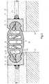
- Fig. 1 einen Querschnitt durch ein Dichtungsband in nicht eingebautem Zustand,
- Fig. 2 das Dichtungsband gem. Fig. 1 während des Eindrückens in einen Hohlraum des Fugenrands, dargestellt in einem Fugenquerschnitt und
- Fig. 3 das vollständig in die Fugenränder eingebaute Dichtungsband, ebenfalls dargestellt in einem Fugenquerschnitt.
- Fig. 1 zeigt ein bevorzugt aus einem gummiartigen Werkstoff wie beispielsweise Neoprene bestehendes Dichtungsband 1, mit einer äußeren Profildecke 2 und einer inneren Profildekke 3. Die äußere Profildecke 2 liegt mit ihrer Oberfläche 4 bündig mit der Verkehrsfläche 5 (vgl. Fig. 3) bzw. der Oberseite 6 der Fugenrandprofile 7. Der den Fugenspalt überbrückende Teil des Dichtungsbands 1 ist als Hohlprofil mit einer Verrippung zwischen der äußeren Profildecke 2 und der inneren Profildecke 3 ausgebildet. Die Verrippung umfaßt vier zu den Profildecken 2, 3 etwa senkrecht verlaufende Rippen 8, wobei jeweils zwischen einer äußeren und einer inneren Rippe 8 diagonal nach unten außen verlaufende Diagonalrippen 9 vorgesehen sind. Die Diagonalrippen 9 bewirken eine seitliche Krafteinleitung in die Fugenränder; sie verhindern zudem ein Aufwölben der äußeren Profildecke 2 in ihrem mittleren Bereich.
- Die seitlichen Ränder des Dichtungsbands weisen jeweils eine in zwei Teile geteilte Verdikkung auf, bestehend aus einem äußeren Verdikkungsteil 10 und einem inneren Verdickungsteil 11. Beide Verdickungsteile 10, 11 besitzen etwa senkrecht auf den anschließenden Profildecken stehende Stützflächen 12, welche an entsprechenden Innenflächen 13 der Fugenrandprofile 7 im Einbauzustand des Dichtungsbands abgestützt sind (vgl. Fig. 2). Der äußere Verdickungsteil 10 weist jeweils einen daran angesetzten Steg 14 mit einer Wulst 15 am Ende des Stegs auf. Der Steg 14 kann dabei, wie in Fig. 1 dargestellt, von vorneherein zur Fugenmitte hin zurückgebogen an dem Verdickungsteil 10 angeformt sein; er kann aber in einer nicht gezeigten Variante auch zur Seite hin gestreckt angeformt sein und erst im Zuge der Montage nach innen zurückgebogen werden. Der innere Verdikkungsteil 11 ist massiver ausgebildet als der äußere Verdickungsteil 10. Der innere Verdikkungsteil 11 besitzt zum äußeren Verdickungsteil 10 hin eine Andrückfläche 16. Zwischen dieser Andrückfläche 16 und der gegenüberliegenden Innenseite 17 der äußeren Profildecke 2 wird die Wulst 15 in dem in den Fig. und 3 gezeigten Einbauzustand des Dichtungsbands verkeilt. Auf der rechten Seite von Fig. 2 ist die Verbindung der seitlichen Verdickung des Dichtungsbands mit dem entsprechenden Fugenrandprofil 7 bereits hergestellt. Die Wulst 15 ist zwischen dem äußeren Verdickungsteil 10 und dem inneren Verdickungsteil 11 zusammengedrückt, d. h. sie verkeilt sich mit deren Innenseiten des Hohlprofils, nämlich einerseits mit der Innenseite 17 der äußeren Profildecke 2, andererseits mit der Andrückfläche 16 des inneren Verdickungsteils 11.
- Auf der linken Seite der Darstellung gem. Fig. 2 wird der Montageablauf gezeigt. Zunächst wird der innere Verdickungsteil 11 mit seiner Stützfläche 12 gegen die entsprechende Innenfläche 13 des Fugenrandprofils 7 in den Hohlraum 18 des Fugenrands eingelegt; danach wird mit einem Drückwerkzeug 27, dessen Ende an der Stützfläche 12 des äußeren Verdickungsteils 10 angesetzt ist, der äußere Verdickungsteil 10 in den verbleibenden Freiraum des Hohlraums 18 des Fugenrandprofils 7 hineingedrückt, bis die Stützfläche 12 hinter die entsprechende Innenfläche 13 des Fugenrandprofils 7, welche an den Hohlraum 18 angrenzt, einschnappt. Während dieses Vorgangs wird auf den Steg 14 ein Zug ausgeübt, welcher eine sichere Verkeilung des Wulstes 15 in der im Bereich des rechten Fugenrands der Fig. 2 dargestellten Lage zur Folge hat.
- Fig. 3 zeigt das komplett eingebaute Dichtungsband mit an die Fuge 19 angrenzendem Betonunterbau 20 und an die Fugenrandprofile 7 angrenzendem Verankerungsbelag 21, bevorzugt aus Kunstharzbeton, in welchem Verankerungsbügel 22 der Fugenrandprofile 7 eingebettet sind.
- Die Fugenrandprofile 7 besitzen ungleich ausgebildete Klauen, welche an die Öffnung der Hohlräume 18 angrenzen. Die äußere Klaue 23 besitzt eine verhältnismäßig schmale Stirnseite 24, mit welcher sie auf der Oberseite der äußeren Profildecke 2 aufliegt. Dabei entsteht ein verhältnismäßig großer, etwa 90° betragender Winkelraum W zwischen der äußeren Profildekke 2 und der äußeren Klaue 23. Dieser Winkelraum W vermeidet eine dauernde Ablagerung von Schmutz bzw. das Eindringen von Schmutz in den Befestigungsbereich zwischen den Verdickungsteilen (10, 11) und dem Fugenrandprofil 7. Die innere Klaue 26 des Fugenrandprofils 7 besitzt eine verlängerte schräge Auflagefläche 25, auf welcher jeweils der äußere Bereich der inneren Profildecke 3 abgestützt ist. Die Auflagefläche 25 verbessert somit die Aufnahme von Vertikallasten durch das Dichtungsband.
Claims (8)
Priority Applications (1)
| Application Number | Priority Date | Filing Date | Title |
|---|---|---|---|
| AT81106812T ATE10762T1 (de) | 1981-08-12 | 1981-09-01 | Vorrichtung zur ueberbrueckung von dehnungsfugen in gehwegen, parkdecks od. dgl. |
Applications Claiming Priority (2)
| Application Number | Priority Date | Filing Date | Title |
|---|---|---|---|
| DE3131804 | 1981-08-12 | ||
| DE3131804A DE3131804C1 (de) | 1981-08-12 | 1981-08-12 | Vorrichtung zur UEberbrueckung von Dehnungsfugen in Gehwegen,Parkdecks od.dgl. |
Publications (2)
| Publication Number | Publication Date |
|---|---|
| EP0071669A1 EP0071669A1 (de) | 1983-02-16 |
| EP0071669B1 true EP0071669B1 (de) | 1984-12-12 |
Family
ID=6139123
Family Applications (1)
| Application Number | Title | Priority Date | Filing Date |
|---|---|---|---|
| EP81106812A Expired EP0071669B1 (de) | 1981-08-12 | 1981-09-01 | Vorrichtung zur Überbrückung von Dehnungsfugen in Gehwegen, Parkdecks od. dgl. |
Country Status (5)
| Country | Link |
|---|---|
| EP (1) | EP0071669B1 (de) |
| AT (1) | ATE10762T1 (de) |
| DE (1) | DE3131804C1 (de) |
| GB (1) | GB2104122B (de) |
| NL (1) | NL190647C (de) |
Families Citing this family (5)
| Publication number | Priority date | Publication date | Assignee | Title |
|---|---|---|---|---|
| AU571608B2 (en) * | 1983-11-28 | 1988-04-21 | Ae Plc | Expansion joint |
| US4685825A (en) * | 1984-05-09 | 1987-08-11 | Friedrick Maurer Sohne Gmbh & Co. Kg | Device for use in expansion joints |
| DE3508010C3 (de) * | 1985-03-06 | 1993-11-18 | Maurer Friedrich Soehne | Anordnung zur Überbrückung einer Dehnungsfuge in einer Fahrbahn |
| EP4438465B1 (de) * | 2023-03-27 | 2026-05-06 | Airbus Operations GmbH | Dichtleiste, steuerflächenanordnung, flugzeugflügel und flugzeug |
| EP4438466B1 (de) * | 2023-03-27 | 2026-01-14 | Airbus Operations GmbH | Dichtleiste, steuerflächenanordnung, flugzeugflügel und flugzeug |
Family Cites Families (6)
| Publication number | Priority date | Publication date | Assignee | Title |
|---|---|---|---|---|
| DE1784069A1 (de) * | 1968-07-04 | 1971-07-15 | Continental Gummi Werke Ag | Dehnfugendichtung |
| US3918824A (en) * | 1973-07-19 | 1975-11-11 | Watson Bowman Associates | Expansion joint seal |
| DE7423559U (de) * | 1974-07-11 | 1975-11-20 | Kober Ag | Dichtungseinlage fuer dehnungsfugen in verkehrsflaechen decken oder waenden von bauwerken |
| US4148167A (en) * | 1977-05-16 | 1979-04-10 | Acme Highway Products Corporation | Concourse seal |
| DE2808386C3 (de) * | 1978-02-27 | 1981-04-09 | Friedrich Maurer Söhne GmbH & Co KG, 8000 München | Vorrichtung zur Überbrückung von Dehnungsfugen, insbesondere in Brücken, Fahrbahnteilen o.dgl. |
| DE2952613B1 (de) * | 1979-12-28 | 1981-01-08 | Kober Ag | Anschlussprofilstreifen,insbesondere an Vorrichtungen zum UEberbruecken von Dehnungsfugen in Bruecken o.dgl. Bauwerken |
-
1981
- 1981-08-12 DE DE3131804A patent/DE3131804C1/de not_active Expired
- 1981-09-01 EP EP81106812A patent/EP0071669B1/de not_active Expired
- 1981-09-01 AT AT81106812T patent/ATE10762T1/de not_active IP Right Cessation
- 1981-09-14 NL NL8104237A patent/NL190647C/xx not_active IP Right Cessation
- 1981-09-15 GB GB08127750A patent/GB2104122B/en not_active Expired
Also Published As
| Publication number | Publication date |
|---|---|
| GB2104122B (en) | 1985-03-20 |
| NL8104237A (nl) | 1983-03-01 |
| NL190647C (nl) | 1994-06-01 |
| EP0071669A1 (de) | 1983-02-16 |
| DE3131804C1 (de) | 1983-02-24 |
| ATE10762T1 (de) | 1984-12-15 |
| GB2104122A (en) | 1983-03-02 |
| NL190647B (nl) | 1994-01-03 |
Similar Documents
| Publication | Publication Date | Title |
|---|---|---|
| DE3416080C2 (de) | Fugenüberbrückungskonstruktion für Brücken o.dgl. Bauwerke | |
| DE2111324A1 (de) | Elastisches Profil zum Abdichten von Fugen,insbesondere zwischen Betonfertigteilen | |
| DE3015011C2 (de) | Vorrichtung zum Überbrücken einer Dehnungsfuge | |
| DE2348117B2 (de) | Kunststoffprofilschiene zur dichtung von fugen zwischen schalungsteilen | |
| EP0071669B1 (de) | Vorrichtung zur Überbrückung von Dehnungsfugen in Gehwegen, Parkdecks od. dgl. | |
| EP0194567B1 (de) | Vorrichtung zur Überbrückung von Dehnungsfugen, insbesondere in Brücken, Fahrbahnteilen oder dergleichen | |
| EP0001836B1 (de) | Aus einzelnen Wandelementen zusammensetzbares Körperelement | |
| DE2647839C3 (de) | Aus Kunststoff bestehendes Fugendichtungsprofil zum Abschließen einer Fuge | |
| DE2808386C3 (de) | Vorrichtung zur Überbrückung von Dehnungsfugen, insbesondere in Brücken, Fahrbahnteilen o.dgl. | |
| DE3202346A1 (de) | Strangfoermige klemmdichtung | |
| EP0054747A1 (de) | Elastomeres Dehnprofil zum Abdichten von bauwerkseitigen Dehnungsfugen | |
| DE3445071A1 (de) | Wasserdichte abdeckung fuer eine bodendehnungsfuge | |
| DE69300527T2 (de) | Dichtung für Automobil-Karrosserieteile. | |
| EP0692584A1 (de) | Dichtung für Arbeitsfugen in und an Betonbauwerken | |
| DE2120313A1 (de) | Dichtungen für Brückenfugen und Straßenfugen | |
| DE4340566A1 (de) | Vorrichtung zur Abdichtung | |
| DE2136842A1 (de) | Vorrichtung zum ueberbruecken von dehnungsfugen in verkehrswegen oder anderen bauwerken | |
| DE2842228C2 (de) | Fugenabdeckung für Dehnungsfugen in Verkehrswegen, insbesondere Brücken | |
| DE3506974C2 (de) | ||
| DE2357318A1 (de) | Verfahren zur herstellung von betonbelaegen und element zum abdichten von fugen und rissen in dem belag | |
| DE9215573U1 (de) | Stoßverbindung | |
| DE2031652B2 (de) | Ankerschiene für die Befestigung eines eine Fensterscheibe od.dgl. umfassenden Dichtungsrahmens an einer Betonwand od. dgl | |
| DE7516672U (de) | Verglasungsprofilsprosse | |
| DE2357108C3 (de) | Vorrichtung zum Überbrücken von Dehnungsfugen | |
| DE8816536U1 (de) | Dichtungsvorrichtung zum Abdichten von bauwerkseitigen Dehnungsfugen, insbesondere für Fahrbahnübergänge |
Legal Events
| Date | Code | Title | Description |
|---|---|---|---|
| PUAI | Public reference made under article 153(3) epc to a published international application that has entered the european phase |
Free format text: ORIGINAL CODE: 0009012 |
|
| AK | Designated contracting states |
Designated state(s): AT BE CH FR LI |
|
| 17P | Request for examination filed |
Effective date: 19830204 |
|
| GRAA | (expected) grant |
Free format text: ORIGINAL CODE: 0009210 |
|
| AK | Designated contracting states |
Designated state(s): AT BE CH FR LI |
|
| REF | Corresponds to: |
Ref document number: 10762 Country of ref document: AT Date of ref document: 19841215 Kind code of ref document: T |
|
| ET | Fr: translation filed | ||
| PLBE | No opposition filed within time limit |
Free format text: ORIGINAL CODE: 0009261 |
|
| STAA | Information on the status of an ep patent application or granted ep patent |
Free format text: STATUS: NO OPPOSITION FILED WITHIN TIME LIMIT |
|
| 26N | No opposition filed | ||
| PG25 | Lapsed in a contracting state [announced via postgrant information from national office to epo] |
Ref country code: BE Effective date: 19870930 |
|
| BERE | Be: lapsed |
Owner name: FRIEDRICH MAURER SOHNE G.M.B.H. & CO K.G. Effective date: 19870930 |
|
| PGFP | Annual fee paid to national office [announced via postgrant information from national office to epo] |
Ref country code: FR Payment date: 19930916 Year of fee payment: 13 |
|
| PGFP | Annual fee paid to national office [announced via postgrant information from national office to epo] |
Ref country code: AT Payment date: 19930924 Year of fee payment: 13 |
|
| PGFP | Annual fee paid to national office [announced via postgrant information from national office to epo] |
Ref country code: CH Payment date: 19931018 Year of fee payment: 13 |
|
| PG25 | Lapsed in a contracting state [announced via postgrant information from national office to epo] |
Ref country code: AT Effective date: 19940901 |
|
| PG25 | Lapsed in a contracting state [announced via postgrant information from national office to epo] |
Ref country code: LI Effective date: 19940930 Ref country code: CH Effective date: 19940930 |
|
| PG25 | Lapsed in a contracting state [announced via postgrant information from national office to epo] |
Ref country code: FR Effective date: 19950531 |
|
| REG | Reference to a national code |
Ref country code: CH Ref legal event code: PL |
|
| REG | Reference to a national code |
Ref country code: FR Ref legal event code: ST |