EP0069922A2 - Procédé de commande de boîtes de vitesses automatiques dans des véhicules automobiles - Google Patents
Procédé de commande de boîtes de vitesses automatiques dans des véhicules automobiles Download PDFInfo
- Publication number
- EP0069922A2 EP0069922A2 EP82105854A EP82105854A EP0069922A2 EP 0069922 A2 EP0069922 A2 EP 0069922A2 EP 82105854 A EP82105854 A EP 82105854A EP 82105854 A EP82105854 A EP 82105854A EP 0069922 A2 EP0069922 A2 EP 0069922A2
- Authority
- EP
- European Patent Office
- Prior art keywords
- transmission
- accelerator pedal
- function
- transmission ratio
- actuated
- Prior art date
- Legal status (The legal status is an assumption and is not a legal conclusion. Google has not performed a legal analysis and makes no representation as to the accuracy of the status listed.)
- Granted
Links
- 230000005540 biological transmission Effects 0.000 title claims abstract description 51
- 238000000034 method Methods 0.000 title claims abstract description 22
- 230000009467 reduction Effects 0.000 claims abstract description 4
- 230000000694 effects Effects 0.000 abstract description 12
- 230000006870 function Effects 0.000 description 6
- 230000008901 benefit Effects 0.000 description 5
- 238000010586 diagram Methods 0.000 description 4
- 230000008859 change Effects 0.000 description 2
- 230000009471 action Effects 0.000 description 1
- 238000010276 construction Methods 0.000 description 1
- 230000001276 controlling effect Effects 0.000 description 1
- 238000011161 development Methods 0.000 description 1
- 230000018109 developmental process Effects 0.000 description 1
- 238000002347 injection Methods 0.000 description 1
- 239000007924 injection Substances 0.000 description 1
- 238000012423 maintenance Methods 0.000 description 1
- 230000001105 regulatory effect Effects 0.000 description 1
- 230000004044 response Effects 0.000 description 1
- 230000000717 retained effect Effects 0.000 description 1
Images

Classifications
-
- F—MECHANICAL ENGINEERING; LIGHTING; HEATING; WEAPONS; BLASTING
- F16—ENGINEERING ELEMENTS AND UNITS; GENERAL MEASURES FOR PRODUCING AND MAINTAINING EFFECTIVE FUNCTIONING OF MACHINES OR INSTALLATIONS; THERMAL INSULATION IN GENERAL
- F16H—GEARING
- F16H61/00—Control functions within control units of change-speed- or reversing-gearings for conveying rotary motion ; Control of exclusively fluid gearing, friction gearing, gearings with endless flexible members or other particular types of gearing
- F16H61/66—Control functions within control units of change-speed- or reversing-gearings for conveying rotary motion ; Control of exclusively fluid gearing, friction gearing, gearings with endless flexible members or other particular types of gearing specially adapted for continuously variable gearings
-
- B—PERFORMING OPERATIONS; TRANSPORTING
- B60—VEHICLES IN GENERAL
- B60W—CONJOINT CONTROL OF VEHICLE SUB-UNITS OF DIFFERENT TYPE OR DIFFERENT FUNCTION; CONTROL SYSTEMS SPECIALLY ADAPTED FOR HYBRID VEHICLES; ROAD VEHICLE DRIVE CONTROL SYSTEMS FOR PURPOSES NOT RELATED TO THE CONTROL OF A PARTICULAR SUB-UNIT
- B60W10/00—Conjoint control of vehicle sub-units of different type or different function
- B60W10/10—Conjoint control of vehicle sub-units of different type or different function including control of change-speed gearings
-
- B—PERFORMING OPERATIONS; TRANSPORTING
- B60—VEHICLES IN GENERAL
- B60W—CONJOINT CONTROL OF VEHICLE SUB-UNITS OF DIFFERENT TYPE OR DIFFERENT FUNCTION; CONTROL SYSTEMS SPECIALLY ADAPTED FOR HYBRID VEHICLES; ROAD VEHICLE DRIVE CONTROL SYSTEMS FOR PURPOSES NOT RELATED TO THE CONTROL OF A PARTICULAR SUB-UNIT
- B60W10/00—Conjoint control of vehicle sub-units of different type or different function
- B60W10/18—Conjoint control of vehicle sub-units of different type or different function including control of braking systems
-
- B—PERFORMING OPERATIONS; TRANSPORTING
- B60—VEHICLES IN GENERAL
- B60W—CONJOINT CONTROL OF VEHICLE SUB-UNITS OF DIFFERENT TYPE OR DIFFERENT FUNCTION; CONTROL SYSTEMS SPECIALLY ADAPTED FOR HYBRID VEHICLES; ROAD VEHICLE DRIVE CONTROL SYSTEMS FOR PURPOSES NOT RELATED TO THE CONTROL OF A PARTICULAR SUB-UNIT
- B60W30/00—Purposes of road vehicle drive control systems not related to the control of a particular sub-unit, e.g. of systems using conjoint control of vehicle sub-units
- B60W30/18—Propelling the vehicle
- B60W30/1819—Propulsion control with control means using analogue circuits, relays or mechanical links
-
- F—MECHANICAL ENGINEERING; LIGHTING; HEATING; WEAPONS; BLASTING
- F16—ENGINEERING ELEMENTS AND UNITS; GENERAL MEASURES FOR PRODUCING AND MAINTAINING EFFECTIVE FUNCTIONING OF MACHINES OR INSTALLATIONS; THERMAL INSULATION IN GENERAL
- F16H—GEARING
- F16H61/00—Control functions within control units of change-speed- or reversing-gearings for conveying rotary motion ; Control of exclusively fluid gearing, friction gearing, gearings with endless flexible members or other particular types of gearing
- F16H61/21—Providing engine brake control
-
- B—PERFORMING OPERATIONS; TRANSPORTING
- B60—VEHICLES IN GENERAL
- B60W—CONJOINT CONTROL OF VEHICLE SUB-UNITS OF DIFFERENT TYPE OR DIFFERENT FUNCTION; CONTROL SYSTEMS SPECIALLY ADAPTED FOR HYBRID VEHICLES; ROAD VEHICLE DRIVE CONTROL SYSTEMS FOR PURPOSES NOT RELATED TO THE CONTROL OF A PARTICULAR SUB-UNIT
- B60W2540/00—Input parameters relating to occupants
- B60W2540/12—Brake pedal position
-
- F—MECHANICAL ENGINEERING; LIGHTING; HEATING; WEAPONS; BLASTING
- F16—ENGINEERING ELEMENTS AND UNITS; GENERAL MEASURES FOR PRODUCING AND MAINTAINING EFFECTIVE FUNCTIONING OF MACHINES OR INSTALLATIONS; THERMAL INSULATION IN GENERAL
- F16H—GEARING
- F16H59/00—Control inputs to control units of change-speed-, or reversing-gearings for conveying rotary motion
- F16H59/14—Inputs being a function of torque or torque demand
- F16H59/18—Inputs being a function of torque or torque demand dependent on the position of the accelerator pedal
-
- F—MECHANICAL ENGINEERING; LIGHTING; HEATING; WEAPONS; BLASTING
- F16—ENGINEERING ELEMENTS AND UNITS; GENERAL MEASURES FOR PRODUCING AND MAINTAINING EFFECTIVE FUNCTIONING OF MACHINES OR INSTALLATIONS; THERMAL INSULATION IN GENERAL
- F16H—GEARING
- F16H59/00—Control inputs to control units of change-speed-, or reversing-gearings for conveying rotary motion
- F16H59/50—Inputs being a function of the status of the machine, e.g. position of doors or safety belts
- F16H59/54—Inputs being a function of the status of the machine, e.g. position of doors or safety belts dependent on signals from the brakes, e.g. parking brakes
Definitions
- the invention is based on a method according to the type of the main claim and the independent claim 2.
- the known arrangement has the disadvantages that a rigid switching of the switching pattern is carried out as a function of the actuation of the brake pedal, so that the duration and thus the intensity of the brake actuation does not have an effect, and that in addition the response of the motor is insufficiently taken into account. Furthermore, it is not taken into account that the increased braking effect should generally be maintained even if the brake pedal has already been released again, but the accelerator pedal has not yet been actuated again.
- the method according to the invention with the characterizing features of the main claim and the independent claim 2 has the advantage that the duration of the brake application and thus the intensity of the desired braking is taken into account, that over-revving the engine is safely avoided and that the increased engine braking effect is maintained as long until the accelerator pedal is pressed again.
- the method according to the invention can be used with advantage if the transmission ratio of the gear used can be adjusted continuously.
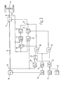
- FIGS. 1 and 2 show block diagrams of two embodiments of devices for carrying out the method according to the invention
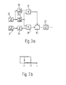
- FIG. 3a shows a variant of the circuit diagrams shown in FIGS. 1 and 2 with definition of a narrow area with little accelerator pedal deflection
- Figure 3b is a diagram for explaining the hysteresis switch shown in Figure 3a.
- 10 denotes the motor of a motor vehicle, which is connected via an input shaft 11 to an automatic transmission 12, which in turn is connected to the output 14 via an output shaft 13.
- an engine speed sensor 15 or an output speed sensor 16 are arranged at the output of the engine 10 or the transmission 12.
- an accelerator pedal 20 and a brake pedal 21 are provided, which act on the function of a transmission control unit 23 in a manner to be described.
- the accelerator pedal 20 is connected to the engine 10 and the transmission control unit 23 in a manner known per se, and on the other hand it is also led to a threshold switch 24 which, when the accelerator pedal 20 is released or approximately released, outputs a positive logic output signal and the output signal zero when the accelerator pedal 20 is deflected .
- the brake pedal 21 is connected to a threshold switch 25, the output signal of which is inversely related to the output signal of the threshold switch 24, that is to say that when the brake pedal 21 is not actuated, the output signal is zero and when the brake pedal 25 is actuated positive logic output signal.
- the function of the brake pedal 21 can also be represented by a switch 22 to the extent of interest here, so that the method according to the invention described below can also be controlled purely manually.
- the output signals of the threshold switches 24, 25 are linked in an AND gate 26, the output of which acts on a transmission control unit 27 arranged downstream of the transmission control unit 23.
- the action is such that with a positive output signal of the AND gate 26, the output signal of the transmission control unit 23 is overridden so that there is an increase in the transmission ratio in the transmission 12, which usually depends on the position of the accelerator pedal 20 and the output signal of the Output speed sensor 16 is set.
- a characteristic curve memory 28 is provided which is controlled by the engine speed sensor 15 and by the output speed sensor 16.
- the characteristic curve memory 28 contains a characteristic curve of maximum engine speed depending on the output speed. If the actual engine speed exceeds the characteristic curve specified in the characteristic curve memory 28, an OR gate 29 connected downstream of the characteristic curve memory 28 is driven, the second, inverted input of which is connected to the output of the threshold value switch 25.
- the output of the OR gate 29 is linked to the output of the threshold switch 24 in an AND gate 30, which controls the hold input of a sample-and-hold stage 31, which is arranged between the translation controller 27 and the transmission 12 .
- FIG. 2 The further device shown in FIG. 2 for carrying out a method according to the invention is largely of the same construction as that shown in FIG. 1, so that the same reference numerals are used.
- a sample-and-hold stage 40 is provided which is controlled by the signal of the output speed sensor 16 and whose hold input is in turn connected to the output of the AND gate 30. At the same time, this controls a changeover switch 43, by means of which the control input of the transmission 12 can be switched from the transmission control 27 to the series connection of a comparator 41 and a controller 42, which are connected downstream of the sample-and-hold stage 40.
- the comparator 41 is controlled at its other input by the output speed sensor 16.
- the driver had only the choice between an operation with a high braking effect and the normal driving program with a very low engine braking effect.
- a method variant can be used, which is illustrated below using the device according to FIG. 3a and the diagram according to FIG. 3b.
- the accelerator pedal 20 is followed by a hysteresis threshold switch 24a instead of a simple threshold switch 24.
- the output signal of the accelerator pedal 20 is fed to a range switch 50, which then emits a positive output signal when the input signal is in a certain narrow range, which is congruent with the hysteresis width of the hysteresis threshold switch 24a.
- the output signals from range switch 50 and hysteresis threshold switch 24a are linked in a further AND gate 51, the output of which is led to the control input of an adjustment stage 52, which is connected between AND gate 26 and translation control 27.
- the hysteresis threshold switch 24a has a characteristic curve as shown in FIG. 3b.
- the method according to the invention described above can be used with particular advantage if the transmission 12 is a continuously variable transmission, since quasi-continuous control is then possible and the transmission ratio can always be adjusted to the extent required by the current driving conditions and the driver's wishes and is desired.
Landscapes
- Engineering & Computer Science (AREA)
- Mechanical Engineering (AREA)
- General Engineering & Computer Science (AREA)
- Chemical & Material Sciences (AREA)
- Combustion & Propulsion (AREA)
- Transportation (AREA)
- Automation & Control Theory (AREA)
- Control Of Transmission Device (AREA)
- Control Of Driving Devices And Active Controlling Of Vehicle (AREA)
Priority Applications (1)
| Application Number | Priority Date | Filing Date | Title |
|---|---|---|---|
| AT82105854T ATE25360T1 (de) | 1981-07-15 | 1982-07-01 | Verfahren zum steuern von automatischen getrieben in kraftfahrzeugen. |
Applications Claiming Priority (4)
| Application Number | Priority Date | Filing Date | Title |
|---|---|---|---|
| DE3127931 | 1981-07-15 | ||
| DE3127931 | 1981-07-15 | ||
| DE3139985 | 1981-10-08 | ||
| DE19813139985 DE3139985A1 (de) | 1981-07-15 | 1981-10-08 | Verfahren zum steuern von automatischen getrieben in kraftfahrzeugen |
Publications (3)
| Publication Number | Publication Date |
|---|---|
| EP0069922A2 true EP0069922A2 (fr) | 1983-01-19 |
| EP0069922A3 EP0069922A3 (en) | 1984-08-29 |
| EP0069922B1 EP0069922B1 (fr) | 1987-02-04 |
Family
ID=25794606
Family Applications (1)
| Application Number | Title | Priority Date | Filing Date |
|---|---|---|---|
| EP82105854A Expired EP0069922B1 (fr) | 1981-07-15 | 1982-07-01 | Procédé de commande de boîtes de vitesses automatiques dans des véhicules automobiles |
Country Status (3)
| Country | Link |
|---|---|
| US (1) | US4501170A (fr) |
| EP (1) | EP0069922B1 (fr) |
| DE (2) | DE3139985A1 (fr) |
Cited By (5)
| Publication number | Priority date | Publication date | Assignee | Title |
|---|---|---|---|---|
| EP0180916A1 (fr) * | 1984-10-31 | 1986-05-14 | Shimadzu Corporation | Système de régulation de la décélération pour automobiles |
| DE3542624A1 (de) * | 1985-12-03 | 1987-06-04 | Michael Meyerle | Regeleinrichtung fuer ein stufenlos einstellbares getriebe fuer kraftfahrzeuge |
| GB2192032A (en) * | 1985-07-08 | 1987-12-31 | Nissan Motor | Control device for transmission |
| EP0280757A1 (fr) * | 1987-03-06 | 1988-09-07 | Michael Meyerle | Dispositif de régulation et de commande pour une boîte de vitesses à variation continue pour véhicules à moteur |
| GB2282861A (en) * | 1993-10-15 | 1995-04-19 | Lucas Ind Plc | Methods and systems for controlling automatic transmission systems to allow engine braking |
Families Citing this family (12)
| Publication number | Priority date | Publication date | Assignee | Title |
|---|---|---|---|---|
| JPS6069355A (ja) * | 1983-09-26 | 1985-04-20 | Honda Motor Co Ltd | 副変速機付車両用変速機の制御装置 |
| DE3334718A1 (de) * | 1983-09-26 | 1985-04-04 | Wabco Westinghouse Fahrzeugbremsen GmbH, 3000 Hannover | Getriebesteuerung fuer ein strassenfahrzeug |
| DE3341652A1 (de) * | 1983-11-18 | 1985-06-05 | Dr.Ing.H.C. F. Porsche Ag, 7000 Stuttgart | Verfahren und vorrichtung zur steuerung einer kupplungs-getriebe-einheit |
| ATE27789T1 (de) * | 1984-02-23 | 1987-07-15 | Knorr Bremse Ag | Fuehrerbremsventil. |
| JPS63167162A (ja) * | 1986-12-27 | 1988-07-11 | Isuzu Motors Ltd | 電子制御自動変速機の制御装置 |
| DE3922040A1 (de) * | 1989-07-05 | 1991-01-17 | Porsche Ag | Verfahren und vorrichtung zur steuerung eines selbsttaetig schaltenden getriebes |
| DE19755076C2 (de) * | 1997-12-11 | 2000-05-31 | Zahnradfabrik Friedrichshafen | Automatgetriebe mit Rückschalt-Funktion |
| EP1013497B1 (fr) * | 1998-12-24 | 2006-05-10 | Eaton Corporation | Contrôle des phases de rétrogradage dans une transmission automatique |
| DE19916637C1 (de) * | 1999-04-13 | 2000-11-23 | Siemens Ag | Verfahren zum Steuern des Antriebsstrangs eines Kraftfahrzeugs und Antriebsstrangsteuerung eines Kraftfahrzeugs |
| DE19952781A1 (de) * | 1999-11-03 | 2001-06-13 | Daimler Chrysler Ag | Verfahren zum Abbremsen eines Fahrzeugs |
| KR100352505B1 (ko) * | 2000-09-06 | 2002-09-16 | 하태환 | 반자동 변속기를 구비한 차량의 브레이크 시스템 |
| JP4438733B2 (ja) * | 2005-10-26 | 2010-03-24 | ソニー株式会社 | 電子機器および電子機器制御方法 |
Citations (6)
| Publication number | Priority date | Publication date | Assignee | Title |
|---|---|---|---|---|
| DE1954757A1 (de) * | 1968-10-30 | 1970-07-02 | Nissan Motor | Steuersystem fuer automatische Kraftfahrzeuguebersetzungsgetriebe |
| US3684066A (en) * | 1969-10-08 | 1972-08-15 | Toyota Motor Co Ltd | Automatic shift control system for automatic transmission |
| DE2165707A1 (de) * | 1971-02-08 | 1972-08-31 | Nissan Motor Co. Ltd., Yokohama (Japan) | Steuersystem für eine automatische Kraftübertragungsanlage |
| FR2305313A1 (fr) * | 1975-03-26 | 1976-10-22 | Bonabel Robert | Dispositif de frein-moteur automatique pour vehicules automobiles a transmission automatique |
| FR2311679A1 (fr) * | 1975-05-21 | 1976-12-17 | Daimler Benz Ag | Systeme de commande pour vehicules, par exemple pour vehicules utilitaires et voitures de tourisme |
| GB2058257A (en) * | 1979-09-12 | 1981-04-08 | Bosch Gmbh Robert | Control apparatus for a stepless transmission |
Family Cites Families (13)
| Publication number | Priority date | Publication date | Assignee | Title |
|---|---|---|---|---|
| FR1600304A (fr) * | 1968-12-31 | 1970-07-20 | ||
| FR2148728A5 (fr) * | 1971-07-30 | 1973-03-23 | Peugeot & Renault | |
| JPS4926929A (fr) * | 1972-07-12 | 1974-03-09 | ||
| DE2329364A1 (de) * | 1973-06-08 | 1975-01-02 | Bosch Gmbh Robert | Automatisches getriebe fuer kraftfahrzeuge |
| JPS50139269A (fr) * | 1974-04-25 | 1975-11-07 | ||
| JPS5259265A (en) * | 1975-11-12 | 1977-05-16 | Nissan Motor Co Ltd | Automatic transmission with downshift maintaining mechanism |
| DE2714559C3 (de) * | 1977-04-01 | 1979-09-13 | Robert Bosch Gmbh, 7000 Stuttgart | Vorrichtung zur Steuerung von Stufengetrieben in Kraftfahrzeugen |
| DE2738914C2 (de) * | 1977-08-29 | 1982-05-06 | Robert Bosch Gmbh, 7000 Stuttgart | Verfahren zum Schalten von Stufengetrieben in Kraftfahrzeugen |
| DE2742032A1 (de) * | 1977-09-19 | 1979-03-29 | Bosch Gmbh Robert | Verfahren und vorrichtung zur einstellung der betaetigungskraft von getriebeteilen in stufengetrieben |
| DE2811574A1 (de) * | 1978-03-17 | 1979-09-27 | Bosch Gmbh Robert | Vorrichtung zur regelung einer antriebsmotor-getriebe-einheit eines kraftfahrzeuges |
| JPS5827421B2 (ja) * | 1978-07-31 | 1983-06-09 | 日産自動車株式会社 | 自動変速機の変速時期制御装置 |
| JPS5833427B2 (ja) * | 1979-03-14 | 1983-07-19 | トヨタ自動車株式会社 | 車輌用変速機の切換制御装置 |
| JPS6010223B2 (ja) * | 1979-07-09 | 1985-03-15 | 日産自動車株式会社 | 自動変速機の変速制御装置 |
-
1981
- 1981-10-08 DE DE19813139985 patent/DE3139985A1/de not_active Withdrawn
-
1982
- 1982-06-23 US US06/391,171 patent/US4501170A/en not_active Expired - Lifetime
- 1982-07-01 EP EP82105854A patent/EP0069922B1/fr not_active Expired
- 1982-07-01 DE DE8282105854T patent/DE3275367D1/de not_active Expired
Patent Citations (6)
| Publication number | Priority date | Publication date | Assignee | Title |
|---|---|---|---|---|
| DE1954757A1 (de) * | 1968-10-30 | 1970-07-02 | Nissan Motor | Steuersystem fuer automatische Kraftfahrzeuguebersetzungsgetriebe |
| US3684066A (en) * | 1969-10-08 | 1972-08-15 | Toyota Motor Co Ltd | Automatic shift control system for automatic transmission |
| DE2165707A1 (de) * | 1971-02-08 | 1972-08-31 | Nissan Motor Co. Ltd., Yokohama (Japan) | Steuersystem für eine automatische Kraftübertragungsanlage |
| FR2305313A1 (fr) * | 1975-03-26 | 1976-10-22 | Bonabel Robert | Dispositif de frein-moteur automatique pour vehicules automobiles a transmission automatique |
| FR2311679A1 (fr) * | 1975-05-21 | 1976-12-17 | Daimler Benz Ag | Systeme de commande pour vehicules, par exemple pour vehicules utilitaires et voitures de tourisme |
| GB2058257A (en) * | 1979-09-12 | 1981-04-08 | Bosch Gmbh Robert | Control apparatus for a stepless transmission |
Cited By (10)
| Publication number | Priority date | Publication date | Assignee | Title |
|---|---|---|---|---|
| EP0180916A1 (fr) * | 1984-10-31 | 1986-05-14 | Shimadzu Corporation | Système de régulation de la décélération pour automobiles |
| US4696380A (en) * | 1984-10-31 | 1987-09-29 | Shimadzu Corporation | Deceleration control system for automobiles |
| GB2192032A (en) * | 1985-07-08 | 1987-12-31 | Nissan Motor | Control device for transmission |
| US4803899A (en) * | 1985-07-08 | 1989-02-14 | Nissan Motor Co., Ltd. | Start up control for transmission |
| GB2192032B (en) * | 1985-07-08 | 1989-07-26 | Nissan Motor | Control device for transmission |
| DE3542624A1 (de) * | 1985-12-03 | 1987-06-04 | Michael Meyerle | Regeleinrichtung fuer ein stufenlos einstellbares getriebe fuer kraftfahrzeuge |
| EP0280757A1 (fr) * | 1987-03-06 | 1988-09-07 | Michael Meyerle | Dispositif de régulation et de commande pour une boîte de vitesses à variation continue pour véhicules à moteur |
| EP0728612A2 (fr) * | 1987-03-06 | 1996-08-28 | Michael Meyerle | Commande pour transmission à variation continue pour véhicules à moteur |
| EP0728612A3 (fr) * | 1987-03-06 | 1996-12-18 | Michael Meyerle | Commande pour transmission à variation continue pour véhicules à moteur |
| GB2282861A (en) * | 1993-10-15 | 1995-04-19 | Lucas Ind Plc | Methods and systems for controlling automatic transmission systems to allow engine braking |
Also Published As
| Publication number | Publication date |
|---|---|
| DE3139985A1 (de) | 1983-02-03 |
| EP0069922A3 (en) | 1984-08-29 |
| US4501170A (en) | 1985-02-26 |
| DE3275367D1 (en) | 1987-03-12 |
| EP0069922B1 (fr) | 1987-02-04 |
Similar Documents
| Publication | Publication Date | Title |
|---|---|---|
| EP0069922B1 (fr) | Procédé de commande de boîtes de vitesses automatiques dans des véhicules automobiles | |
| DE69025540T2 (de) | Laufzustand-Steuerungssystem für ein Kraftfahrzeug | |
| DE19509494C2 (de) | Vorrichtung zur Regulierung der Fahrgeschwindigkeit eines Kraftfahrzeuges | |
| DE69029894T2 (de) | Selbstanpassendes Steuerungssystem für Fahrzeuge | |
| DE3139838C2 (de) | Steuervorrichtung für ein Automatikgetriebe in einem Kraftfahrzeug | |
| DE69806534T2 (de) | Steuerung für Servo-Schaltung | |
| DE3636953C2 (fr) | ||
| DE69703713T2 (de) | Schalten von einem Reisegeschwindigkeits-Steuerungssystem mit Fahrzeugfolgemodalität | |
| DE19620929A1 (de) | Längsregelsystem für Kraftfahrzeuge mit haptischem Gaspedal | |
| DE19952289B4 (de) | Automatisches Geschwindigkeitsänderungssteuerverfahren und automatische Geschwindigkeitsänderungssteuerungsvorrichtung | |
| DE2719350A1 (de) | Vorrichtung zur ermittlung des schaltrucks in kraftfahrzeugen | |
| DE3201440C2 (fr) | ||
| DE2842389A1 (de) | Vorrichtung zur einstellung des drehmomentes einer brennkraftmaschine | |
| DE2843256A1 (de) | Vorrichtung zur regelung einer kraftfahrzeug-antriebseinheit | |
| DE19748424A1 (de) | Verfahren zur fahrverhaltensadaptiven Steuerung eines variabel einstellbaren Kraftfahrzeugaggregates | |
| DE2900461A1 (de) | Einrichtung zur regelung der fahrgeschwindigkeit eines fahrzeugs | |
| DE3151351A1 (de) | Verfahren und vorrichtung zur steuerung einer kraftfahrzeug-antriebseinheit | |
| DE19630156B4 (de) | Steuerung eines selbsttätig schaltenden Getriebes oder eines stufenlosen Getriebes | |
| DE2537006A1 (de) | Wechselgetriebe fuer kraftfahrzeuge | |
| DE69302797T2 (de) | Steuervorrichtung für ein automatisiertes Getriebe eines Nutzfahrzeuges | |
| EP0676565A2 (fr) | Procédé et dispositif de commande pour transmission à variation continue | |
| DE4002325A1 (de) | Schaltkennfeld eines automatikgetriebes und verfahren zum ermitteln eines schaltsignals aus dem schaltkennfeld | |
| DE2755202C2 (fr) | ||
| DE19537273A1 (de) | Einrichtung zur Geschwindigkeitsregelung von Fahrzeugen | |
| EP1077827A1 (fr) | Dispositif de commande de moteur de vehicule avec regulation et/ou limitation de la vitesse de roulement |
Legal Events
| Date | Code | Title | Description |
|---|---|---|---|
| PUAI | Public reference made under article 153(3) epc to a published international application that has entered the european phase |
Free format text: ORIGINAL CODE: 0009012 |
|
| 17P | Request for examination filed |
Effective date: 19820701 |
|
| AK | Designated contracting states |
Designated state(s): AT BE CH DE FR GB IT LI NL SE |
|
| PUAL | Search report despatched |
Free format text: ORIGINAL CODE: 0009013 |
|
| AK | Designated contracting states |
Designated state(s): AT BE CH DE FR GB IT LI NL SE |
|
| RHK1 | Main classification (correction) |
Ipc: B60K 41/26 |
|
| GRAA | (expected) grant |
Free format text: ORIGINAL CODE: 0009210 |
|
| AK | Designated contracting states |
Kind code of ref document: B1 Designated state(s): AT BE CH DE FR GB IT LI NL SE |
|
| REF | Corresponds to: |
Ref document number: 25360 Country of ref document: AT Date of ref document: 19870215 Kind code of ref document: T |
|
| REF | Corresponds to: |
Ref document number: 3275367 Country of ref document: DE Date of ref document: 19870312 |
|
| ET | Fr: translation filed | ||
| ITF | It: translation for a ep patent filed | ||
| PGFP | Annual fee paid to national office [announced via postgrant information from national office to epo] |
Ref country code: NL Payment date: 19870731 Year of fee payment: 6 |
|
| REG | Reference to a national code |
Ref country code: GB Ref legal event code: 746 |
|
| PLBE | No opposition filed within time limit |
Free format text: ORIGINAL CODE: 0009261 |
|
| STAA | Information on the status of an ep patent application or granted ep patent |
Free format text: STATUS: NO OPPOSITION FILED WITHIN TIME LIMIT |
|
| 26N | No opposition filed | ||
| REG | Reference to a national code |
Ref country code: FR Ref legal event code: DL |
|
| REG | Reference to a national code |
Ref country code: FR Ref legal event code: DL |
|
| PG25 | Lapsed in a contracting state [announced via postgrant information from national office to epo] |
Ref country code: AT Effective date: 19890701 |
|
| PG25 | Lapsed in a contracting state [announced via postgrant information from national office to epo] |
Ref country code: LI Effective date: 19890731 Ref country code: CH Effective date: 19890731 Ref country code: BE Effective date: 19890731 |
|
| BERE | Be: lapsed |
Owner name: ROBERT BOSCH G.M.B.H. Effective date: 19890731 |
|
| PG25 | Lapsed in a contracting state [announced via postgrant information from national office to epo] |
Ref country code: NL Effective date: 19900201 |
|
| NLV4 | Nl: lapsed or anulled due to non-payment of the annual fee | ||
| REG | Reference to a national code |
Ref country code: CH Ref legal event code: PL |
|
| PGFP | Annual fee paid to national office [announced via postgrant information from national office to epo] |
Ref country code: SE Payment date: 19910826 Year of fee payment: 10 |
|
| PG25 | Lapsed in a contracting state [announced via postgrant information from national office to epo] |
Ref country code: SE Effective date: 19920702 |
|
| EUG | Se: european patent has lapsed |
Ref document number: 82105854.2 Effective date: 19930204 |
|
| PGFP | Annual fee paid to national office [announced via postgrant information from national office to epo] |
Ref country code: GB Payment date: 20010618 Year of fee payment: 20 |
|
| PGFP | Annual fee paid to national office [announced via postgrant information from national office to epo] |
Ref country code: FR Payment date: 20010723 Year of fee payment: 20 |
|
| PGFP | Annual fee paid to national office [announced via postgrant information from national office to epo] |
Ref country code: DE Payment date: 20011002 Year of fee payment: 20 |
|
| REG | Reference to a national code |
Ref country code: GB Ref legal event code: IF02 |
|
| PG25 | Lapsed in a contracting state [announced via postgrant information from national office to epo] |
Ref country code: GB Free format text: LAPSE BECAUSE OF EXPIRATION OF PROTECTION Effective date: 20020630 |
|
| REG | Reference to a national code |
Ref country code: GB Ref legal event code: PE20 Effective date: 20020630 |