EP0065713A1 - Dispositif à vide pour maintenir sous tension des films ou des matériaux analogues - Google Patents
Dispositif à vide pour maintenir sous tension des films ou des matériaux analogues Download PDFInfo
- Publication number
- EP0065713A1 EP0065713A1 EP82104178A EP82104178A EP0065713A1 EP 0065713 A1 EP0065713 A1 EP 0065713A1 EP 82104178 A EP82104178 A EP 82104178A EP 82104178 A EP82104178 A EP 82104178A EP 0065713 A1 EP0065713 A1 EP 0065713A1
- Authority
- EP
- European Patent Office
- Prior art keywords
- film
- channels
- cylinder
- partial areas
- scanners
- Prior art date
- Legal status (The legal status is an assumption and is not a legal conclusion. Google has not performed a legal analysis and makes no representation as to the accuracy of the status listed.)
- Withdrawn
Links
Images
Classifications
-
- H—ELECTRICITY
- H04—ELECTRIC COMMUNICATION TECHNIQUE
- H04N—PICTORIAL COMMUNICATION, e.g. TELEVISION
- H04N1/00—Scanning, transmission or reproduction of documents or the like, e.g. facsimile transmission; Details thereof
- H04N1/04—Scanning arrangements, i.e. arrangements for the displacement of active reading or reproducing elements relative to the original or reproducing medium, or vice versa
- H04N1/06—Scanning arrangements, i.e. arrangements for the displacement of active reading or reproducing elements relative to the original or reproducing medium, or vice versa using cylindrical picture-bearing surfaces, i.e. scanning a main-scanning line substantially perpendicular to the axis and lying in a curved cylindrical surface
- H04N1/08—Mechanisms for mounting or holding the sheet around the drum
- H04N1/083—Holding means
- H04N1/0856—Suction or vacuum means
-
- B—PERFORMING OPERATIONS; TRANSPORTING
- B41—PRINTING; LINING MACHINES; TYPEWRITERS; STAMPS
- B41F—PRINTING MACHINES OR PRESSES
- B41F27/00—Devices for attaching printing elements or formes to supports
- B41F27/12—Devices for attaching printing elements or formes to supports for attaching flexible printing formes
- B41F27/1212—Devices for attaching printing elements or formes to supports for attaching flexible printing formes using pneumatic force
-
- G—PHYSICS
- G03—PHOTOGRAPHY; CINEMATOGRAPHY; ANALOGOUS TECHNIQUES USING WAVES OTHER THAN OPTICAL WAVES; ELECTROGRAPHY; HOLOGRAPHY
- G03B—APPARATUS OR ARRANGEMENTS FOR TAKING PHOTOGRAPHS OR FOR PROJECTING OR VIEWING THEM; APPARATUS OR ARRANGEMENTS EMPLOYING ANALOGOUS TECHNIQUES USING WAVES OTHER THAN OPTICAL WAVES; ACCESSORIES THEREFOR
- G03B27/00—Photographic printing apparatus
- G03B27/32—Projection printing apparatus, e.g. enlarger, copying camera
- G03B27/52—Details
- G03B27/62—Holders for the original
- G03B27/64—Holders for the original using a vacuum or fluid pressure
-
- H—ELECTRICITY
- H04—ELECTRIC COMMUNICATION TECHNIQUE
- H04N—PICTORIAL COMMUNICATION, e.g. TELEVISION
- H04N1/00—Scanning, transmission or reproduction of documents or the like, e.g. facsimile transmission; Details thereof
- H04N1/04—Scanning arrangements, i.e. arrangements for the displacement of active reading or reproducing elements relative to the original or reproducing medium, or vice versa
- H04N1/06—Scanning arrangements, i.e. arrangements for the displacement of active reading or reproducing elements relative to the original or reproducing medium, or vice versa using cylindrical picture-bearing surfaces, i.e. scanning a main-scanning line substantially perpendicular to the axis and lying in a curved cylindrical surface
- H04N1/08—Mechanisms for mounting or holding the sheet around the drum
Definitions
- Vacuum clamping device for films or film-like materials.
- the invention relates to reproduction technology and relates to a device for clamping films by means of vacuum, in particular to scanning and writing cylinders of high-speed drum scanners.
- the present invention has for its object to provide a vacuum clamping device for films on high-speed drum scanners, which avoids the disadvantages mentioned.
- the invention achieves this in that the clamping surface is a has leather-grain-like structure, which consists of a plurality of irregularly shaped and irregularly arranged partial surfaces, the partial surfaces being parts of the original cylinder surface, that the individual partial surfaces are separated from one another by flat, narrow, closed channels, such that these channels are arranged in such a way that they are connected to each other and that the channels are connected to the evacuated cylinder interior by at least one bore.
- the invention is explained below with reference to the figure.
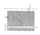
- the figure shows a partial section from the cylinder surface.
- the arrangement of the partial areas and channels can be seen from the figure. It can be seen that the channel width - shown here only as the line width between the partial areas - is small compared to the irregularly shaped partial areas 1 and that the network of channels is self-contained. Experience has shown that the depth of the channels only needs to be a few 10th millimeters. You can e.g. B. can be produced by etching, engraving, eroding or by means of high-energy rays.
- the arrangement of the bores 4 distributed over the cylinder surface can also be seen from the drawing, via which the channels produce with the inside of the cylinder. vacuum. At the bottom, the figure shows a strip 2, which is aligned with the axis device of the cylinder is parallel and does not have the pattern described.
- the invention is advantageously applied to high-speed drum scanners in reproduction technology.
- the application is not limited to this.
- the application e.g. B. by means of vacuum films or film-like materials on plan cassettes, film stages of cameras, copiers, enlargers or the like.
Landscapes
- Engineering & Computer Science (AREA)
- Multimedia (AREA)
- Signal Processing (AREA)
- Physics & Mathematics (AREA)
- Fluid Mechanics (AREA)
- General Physics & Mathematics (AREA)
- Facsimile Scanning Arrangements (AREA)
- Preparing Plates And Mask In Photomechanical Process (AREA)
- Feeding Of Articles By Means Other Than Belts Or Rollers (AREA)
- Advancing Webs (AREA)
Applications Claiming Priority (2)
| Application Number | Priority Date | Filing Date | Title |
|---|---|---|---|
| DE3120172 | 1981-05-21 | ||
| DE19813120172 DE3120172A1 (de) | 1981-05-21 | 1981-05-21 | Vakuumspanneinrichtung fuer filme oder filmaehnliche materialien |
Publications (1)
| Publication Number | Publication Date |
|---|---|
| EP0065713A1 true EP0065713A1 (fr) | 1982-12-01 |
Family
ID=6132852
Family Applications (1)
| Application Number | Title | Priority Date | Filing Date |
|---|---|---|---|
| EP82104178A Withdrawn EP0065713A1 (fr) | 1981-05-21 | 1982-05-13 | Dispositif à vide pour maintenir sous tension des films ou des matériaux analogues |
Country Status (8)
| Country | Link |
|---|---|
| EP (1) | EP0065713A1 (fr) |
| JP (1) | JPS57198462A (fr) |
| AU (1) | AU8371082A (fr) |
| BR (1) | BR8203000A (fr) |
| DD (1) | DD202075A5 (fr) |
| DE (1) | DE3120172A1 (fr) |
| DK (1) | DK231782A (fr) |
| YU (1) | YU104082A (fr) |
Families Citing this family (3)
| Publication number | Priority date | Publication date | Assignee | Title |
|---|---|---|---|---|
| DE3226280A1 (de) * | 1982-07-14 | 1984-01-19 | H. Jürgen Prof. Dr. 4400 Münster Andrä | Film-andruck-verfahren |
| DE3927162A1 (de) * | 1989-08-17 | 1991-02-21 | Hell Rudolf Dr Ing Gmbh | Vorrichtung zum automatischen auf- und abspannen von aufzeichnungsmaterial und betriebsweise der vorrichtung |
| AU629973B2 (en) * | 1989-08-17 | 1992-10-15 | Linotype-Hell Ag | Device for automatically clamping and releasing data supports and its operation |
Citations (3)
| Publication number | Priority date | Publication date | Assignee | Title |
|---|---|---|---|---|
| US3380381A (en) * | 1965-08-06 | 1968-04-30 | Western Printing Mach Co | Rotary press printing cylinder for clamping flexible plates |
| FR2196910A1 (fr) * | 1972-08-24 | 1974-03-22 | Schulz Juergen | |
| US4005653A (en) * | 1974-09-09 | 1977-02-01 | Livermore And Knight Co., Inc. | Vacuum cylinder for printing presses |
-
1981
- 1981-05-21 DE DE19813120172 patent/DE3120172A1/de not_active Withdrawn
-
1982
- 1982-05-13 EP EP82104178A patent/EP0065713A1/fr not_active Withdrawn
- 1982-05-14 AU AU83710/82A patent/AU8371082A/en not_active Abandoned
- 1982-05-17 YU YU104082A patent/YU104082A/xx unknown
- 1982-05-20 JP JP8413382A patent/JPS57198462A/ja active Pending
- 1982-05-20 DD DD24004782A patent/DD202075A5/de unknown
- 1982-05-21 BR BR8203000A patent/BR8203000A/pt unknown
- 1982-05-21 DK DK231782A patent/DK231782A/da not_active Application Discontinuation
Patent Citations (3)
| Publication number | Priority date | Publication date | Assignee | Title |
|---|---|---|---|---|
| US3380381A (en) * | 1965-08-06 | 1968-04-30 | Western Printing Mach Co | Rotary press printing cylinder for clamping flexible plates |
| FR2196910A1 (fr) * | 1972-08-24 | 1974-03-22 | Schulz Juergen | |
| US4005653A (en) * | 1974-09-09 | 1977-02-01 | Livermore And Knight Co., Inc. | Vacuum cylinder for printing presses |
Also Published As
| Publication number | Publication date |
|---|---|
| AU8371082A (en) | 1982-11-25 |
| DD202075A5 (de) | 1983-08-24 |
| YU104082A (en) | 1985-03-20 |
| BR8203000A (pt) | 1983-05-10 |
| DE3120172A1 (de) | 1982-12-09 |
| DK231782A (da) | 1982-11-22 |
| JPS57198462A (en) | 1982-12-06 |
Similar Documents
| Publication | Publication Date | Title |
|---|---|---|
| DE3118458C2 (de) | Lichtaufnahme-Vorrichtung | |
| DE2707170A1 (de) | Pneumatische bremse | |
| DE1256696B (de) | Vorrichtung zur selbsttaetigen Abstandhaltung zwischen Aufzeichnungs- bzw. Abnahmeelementen und relativ dazu bewegten Aufzeichnungstraegern | |
| DE1907212B2 (de) | Verfahren zum Auftragen magnetisierbarer bindemittelhaltiger Schichten auf eine Trägerfolie mit einem ExtrudergieBer | |
| DE2248873B2 (de) | Stereo-Bildwiedergabesystem | |
| EP0065713A1 (fr) | Dispositif à vide pour maintenir sous tension des films ou des matériaux analogues | |
| DE1524769A1 (de) | Vorrichtung zum Bandtransport und zur Bandabstandssteuerung | |
| DE2952209C2 (de) | Anordnung zur punkt- und zeilenweisen Aufzeichnung von Bildinformationen | |
| DE2056812C3 (de) | Vorrichtung zum Abtasten eines von der Erdoberfläche ausgehenden Abtaststrahls | |
| DE1498652A1 (de) | Anordnung zur Steuerung der Verstellgeschwindigkeit einer zu untersuchenden Probe,insbesondere fuer registrierende Dichtemesser | |
| EP0593961A1 (fr) | Séparateur de faisceaux optique spécialement pour un faisceau laser | |
| CH674585A5 (fr) | ||
| DE2632976A1 (de) | Lagerung fuer einen offenend-spinnrotor | |
| DE8115093U1 (de) | Vakuumspanneinrichtung fuer filme oder filmaehnliche materialien | |
| DE3048373A1 (de) | Vorrichtung zur fotografischen aufnahme und wiedergabe von farbbildern nach dem linsenrasterprinzip | |
| DE2453343C2 (de) | Filmführung im Bildfensterbereich eines \ kinematographischen Aufnahme- oder Wiedergabegerätes | |
| DE2634759C3 (de) | Einrichtung zur Bildung eines Luftlagers für ein Magnetband | |
| DE1796211A1 (de) | Anordnung zur farbigen Wiedergabe latenter Aufzeichnungen magnetischer oder elektrostatischer Natur | |
| DE2349041A1 (de) | Lichtsetzmaschine | |
| DE3239616C2 (fr) | ||
| DE677591C (de) | Elektrostatisch gesteuertes Lichtventil | |
| DE2350290C2 (de) | Tintenstrahl-Aufzeichnungsvorrichtung | |
| DE582179C (de) | Verfahren zur Beseitigung nichtlinearer und/oder Phasenverzerrungen bei der Wiedergabe von Lichttonaufzeichnungen mittels spaltabbildender Optik | |
| DE1922801C3 (de) | Photographischer Apparat mit Schlitzverschluß | |
| DE2329156C3 (de) | Tonbandbefestigung an Diapositivrahmen |
Legal Events
| Date | Code | Title | Description |
|---|---|---|---|
| PUAI | Public reference made under article 153(3) epc to a published international application that has entered the european phase |
Free format text: ORIGINAL CODE: 0009012 |
|
| AK | Designated contracting states |
Designated state(s): AT BE CH DE FR GB IT LI NL SE |
|
| 17P | Request for examination filed |
Effective date: 19821023 |
|
| STAA | Information on the status of an ep patent application or granted ep patent |
Free format text: STATUS: THE APPLICATION IS DEEMED TO BE WITHDRAWN |
|
| 18D | Application deemed to be withdrawn |
Effective date: 19840111 |
|
| RIN1 | Information on inventor provided before grant (corrected) |
Inventor name: PARL, ULRICH Inventor name: BLOCK, DIETER Inventor name: HOMFELDT, VOLKER Inventor name: GESELL REINHARD |