EP0065713A1 - Vacuum tensioning device for films or film-like materials - Google Patents
Vacuum tensioning device for films or film-like materials Download PDFInfo
- Publication number
- EP0065713A1 EP0065713A1 EP82104178A EP82104178A EP0065713A1 EP 0065713 A1 EP0065713 A1 EP 0065713A1 EP 82104178 A EP82104178 A EP 82104178A EP 82104178 A EP82104178 A EP 82104178A EP 0065713 A1 EP0065713 A1 EP 0065713A1
- Authority
- EP
- European Patent Office
- Prior art keywords
- film
- channels
- cylinder
- partial areas
- scanners
- Prior art date
- Legal status (The legal status is an assumption and is not a legal conclusion. Google has not performed a legal analysis and makes no representation as to the accuracy of the status listed.)
- Withdrawn
Links
Images
Classifications
-
- H—ELECTRICITY
- H04—ELECTRIC COMMUNICATION TECHNIQUE
- H04N—PICTORIAL COMMUNICATION, e.g. TELEVISION
- H04N1/00—Scanning, transmission or reproduction of documents or the like, e.g. facsimile transmission; Details thereof
- H04N1/04—Scanning arrangements, i.e. arrangements for the displacement of active reading or reproducing elements relative to the original or reproducing medium, or vice versa
- H04N1/06—Scanning arrangements, i.e. arrangements for the displacement of active reading or reproducing elements relative to the original or reproducing medium, or vice versa using cylindrical picture-bearing surfaces, i.e. scanning a main-scanning line substantially perpendicular to the axis and lying in a curved cylindrical surface
- H04N1/08—Mechanisms for mounting or holding the sheet around the drum
- H04N1/083—Holding means
- H04N1/0856—Suction or vacuum means
-
- B—PERFORMING OPERATIONS; TRANSPORTING
- B41—PRINTING; LINING MACHINES; TYPEWRITERS; STAMPS
- B41F—PRINTING MACHINES OR PRESSES
- B41F27/00—Devices for attaching printing elements or formes to supports
- B41F27/12—Devices for attaching printing elements or formes to supports for attaching flexible printing formes
- B41F27/1212—Devices for attaching printing elements or formes to supports for attaching flexible printing formes using pneumatic force
-
- G—PHYSICS
- G03—PHOTOGRAPHY; CINEMATOGRAPHY; ANALOGOUS TECHNIQUES USING WAVES OTHER THAN OPTICAL WAVES; ELECTROGRAPHY; HOLOGRAPHY
- G03B—APPARATUS OR ARRANGEMENTS FOR TAKING PHOTOGRAPHS OR FOR PROJECTING OR VIEWING THEM; APPARATUS OR ARRANGEMENTS EMPLOYING ANALOGOUS TECHNIQUES USING WAVES OTHER THAN OPTICAL WAVES; ACCESSORIES THEREFOR
- G03B27/00—Photographic printing apparatus
- G03B27/32—Projection printing apparatus, e.g. enlarger, copying camera
- G03B27/52—Details
- G03B27/62—Holders for the original
- G03B27/64—Holders for the original using a vacuum or fluid pressure
-
- H—ELECTRICITY
- H04—ELECTRIC COMMUNICATION TECHNIQUE
- H04N—PICTORIAL COMMUNICATION, e.g. TELEVISION
- H04N1/00—Scanning, transmission or reproduction of documents or the like, e.g. facsimile transmission; Details thereof
- H04N1/04—Scanning arrangements, i.e. arrangements for the displacement of active reading or reproducing elements relative to the original or reproducing medium, or vice versa
- H04N1/06—Scanning arrangements, i.e. arrangements for the displacement of active reading or reproducing elements relative to the original or reproducing medium, or vice versa using cylindrical picture-bearing surfaces, i.e. scanning a main-scanning line substantially perpendicular to the axis and lying in a curved cylindrical surface
- H04N1/08—Mechanisms for mounting or holding the sheet around the drum
Definitions
- Vacuum clamping device for films or film-like materials.
- the invention relates to reproduction technology and relates to a device for clamping films by means of vacuum, in particular to scanning and writing cylinders of high-speed drum scanners.
- the present invention has for its object to provide a vacuum clamping device for films on high-speed drum scanners, which avoids the disadvantages mentioned.
- the invention achieves this in that the clamping surface is a has leather-grain-like structure, which consists of a plurality of irregularly shaped and irregularly arranged partial surfaces, the partial surfaces being parts of the original cylinder surface, that the individual partial surfaces are separated from one another by flat, narrow, closed channels, such that these channels are arranged in such a way that they are connected to each other and that the channels are connected to the evacuated cylinder interior by at least one bore.
- the invention is explained below with reference to the figure.
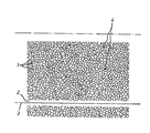
- the figure shows a partial section from the cylinder surface.
- the arrangement of the partial areas and channels can be seen from the figure. It can be seen that the channel width - shown here only as the line width between the partial areas - is small compared to the irregularly shaped partial areas 1 and that the network of channels is self-contained. Experience has shown that the depth of the channels only needs to be a few 10th millimeters. You can e.g. B. can be produced by etching, engraving, eroding or by means of high-energy rays.
- the arrangement of the bores 4 distributed over the cylinder surface can also be seen from the drawing, via which the channels produce with the inside of the cylinder. vacuum. At the bottom, the figure shows a strip 2, which is aligned with the axis device of the cylinder is parallel and does not have the pattern described.
- the invention is advantageously applied to high-speed drum scanners in reproduction technology.
- the application is not limited to this.
- the application e.g. B. by means of vacuum films or film-like materials on plan cassettes, film stages of cameras, copiers, enlargers or the like.
Abstract
Description
Vakuumspanneinrichtung für Filme oder filmähnliche Materialien.Vacuum clamping device for films or film-like materials.
Die Erfindung bezieht sich auf die Reproduktionstechnik und betrifft eine Einrichtung zum Aufspannen von Filmen mittels Vakuum, insbesondere auf Abtast- und Schreibzylinder von schnellaufenden Trommelscannern.The invention relates to reproduction technology and relates to a device for clamping films by means of vacuum, in particular to scanning and writing cylinders of high-speed drum scanners.
Es sind Einrichtungen der genannten Art bekannt, bei denen in die Oberfläche der Zylinder in einigem Abstand von den Formatkanten des Films Kanäle eingearbeitet sind, die durch Bohrungen aus dem Inneren des Zylinders evakuiert werden und den Film an den Kanten ansaugen. Die Mitte des Filmformates aber, gerade jene Partien also, an denen die Fliehkräfte bei Rotation des Zylinders angreifen, wird nicht niedergehalten, weil durch die dichtende Wirkung der Kanalkanten die Vakuumkräfte nicht bis unter die große Filmfläche durchgreifen. Die Folge ist, daß sich bei höheren Laufgeschwindigkeiten die Formatmitte abhebt, wobei die Formatkanten über die Zylinderoberfläche zu gleiten beginnen, bis schließlich das Vakuum in den Kanälen zusammenbricht und der Film vom Zylinder abfliegt.Devices of the type mentioned are known, in which channels are machined into the surface of the cylinders at some distance from the format edges of the film, which channels are evacuated through bores from the interior of the cylinder and suck the film in at the edges. The middle of the film format, however, precisely those areas on which the centrifugal forces act when the cylinder rotates, is not held down because the sealing forces of the channel edges prevent the vacuum forces from reaching below the large film surface. The result is that the center of the format stands out at higher running speeds, the format edges beginning to slide over the cylinder surface until closing The vacuum in the channels breaks down and the film flies off the cylinder.
Die Trommeldrehzahlen wie auch die Durchmesser moderner Scanner werden immer größer. Die Fliehkräfte wachsen linear mit der Masse des Films und quadratisch mit der Drehzahl an. Die beschriebene Anordnung kann modernen Scannern deshalb nicht mehr gerecht werden.The drum speed and the diameter of modern scanners are getting bigger. The centrifugal forces increase linearly with the mass of the film and quadratically with the speed. The arrangement described can therefore no longer do justice to modern scanners.
Man hat deshalb versucht, durch viele regulär angeordnete Bohrungen und/oder Kanäle, die über das gesamte Filmformat verteilt sind, diese Schwierigkeiten zu umgehen, jedoch zeigt sich dabei, daß sich der Film am Ort der Löcher oder Kanäle durch die Vakuumkräfte leicht einzieht. Bedenkt man weiterhin, daß moderne Scanner gerastete Aufzeichnungen machen und daß die Apertur der Abtast- bzw. Schreiborgane eventuell recht groß ist, dann erkennt man leicht, daß sich durch "Einziehungen" des Films an den Vakuumsaugstellen sehr leicht Fehler in der Rasterpunktform, -größe und -schärfe ergeben. Diese treten im aufgezeichneten Bild periodisch in Erscheinung und werden gerade dadurch vom Auge als außerordentlich störend empfunden, zumal sie mit aufgezeichneten Rastern moireähnliche Erscheinungen bilden können.Attempts have therefore been made to circumvent these difficulties through many regularly arranged bores and / or channels which are distributed over the entire film format, but it is found that the film is easily drawn in by the vacuum forces at the location of the holes or channels. If you also consider that modern scanners make latched recordings and that the aperture of the scanning or writing elements may be quite large, it is easy to see that "pinching" of the film at the vacuum suction points very easily leads to errors in the dot shape, size and sharpness result. These appear periodically in the recorded image and are perceived as extremely disturbing by the eye, especially since they can form moire-like appearances with recorded grids.
Der vorliegenden Erfindung liegt die Aufgabe zugrunde, eine Vakuumspanneinrichtung für Filme auf schnellaufenden Trommelscannern anzugeben, die die genannten Nachteile vermeidet. Die Erfindung erreicht dies dadurch, daß die Aufspannfläche eine ledernarbenartige Struktur aufweist, die aus einer Vielzahl irregulär geformter und zueinander irregulär angeordneter Teilflächen besteht, wobei die Teilflächen Teile der ursprünglichen Zylinderoberfläche sind, daß die einzelnen Teilflächen durch flache, schmale in sich geschlossene Kanäle voneinander getrennt sind, daß diese Kanäle so angeordnet sind, daß sie miteinander in Verbindung stehen und daß die Kanäle durch mindestens eine Bohrung mit dem evakuierten Zylinderinneren in Verbindung stehen.The present invention has for its object to provide a vacuum clamping device for films on high-speed drum scanners, which avoids the disadvantages mentioned. The invention achieves this in that the clamping surface is a has leather-grain-like structure, which consists of a plurality of irregularly shaped and irregularly arranged partial surfaces, the partial surfaces being parts of the original cylinder surface, that the individual partial surfaces are separated from one another by flat, narrow, closed channels, such that these channels are arranged in such a way that they are connected to each other and that the channels are connected to the evacuated cylinder interior by at least one bore.
Die Erfindung wird im folgenden an Hand der Figur näher erläutert. Die Figur zeigt einen Teilausschnitt aus der Zylinderoberfläche.The invention is explained below with reference to the figure. The figure shows a partial section from the cylinder surface.
Anordnung der Teilflächen und Kanäle sind aus der Figur ersichtlich. Man erkennt, daß die Kanalbreite - hier nur als die Strichstärke zwischen den Teilflächen wiedergegeben - klein ist gegen die irregulär geformten Teilflächen 1 und daß das Netz der Kanäle in sich geschlossen ist. Die Tiefe der Kanäle braucht erfahrungsgemäß nur einige lOtel Millimeter zu betragen. Sie können z. B. durch Ätzen, Gravieren, Erodieren oder mittels Hochenergiestrahlen hergestellt werden. Ebenfalls ist aus der Zeichnung die Anordnung der über die Zylinderoberfläche verteilten Bohrungen 4 zu ersehen, über die die Kanäle mit dem im Innern des Zylinders erzeug- . ten Vakuum in Verbindung stehen. Am unteren Rande zeigt die Figur einen Streifen 2, der zur Achsrichtung des Zylinders parallel liegt und das beschriebene Muster nicht aufweist. Das heißt, er besteht aus der ursprünglichen Zylinderoberfläche. Davon sind mehrere so am Zylinderumfang angeordnet, daß die achsparallelen Kanten 3 gängiger Filmformate auf diese Streifen zu liegen kommen. Die Formatkante des Films wird dadurch besonders fest niedergehalten, weil das Netz der Kanäle in der Nähe der Filmkante 3 verschlossen ist und von dorther keine Luft nachströmen kann.The arrangement of the partial areas and channels can be seen from the figure. It can be seen that the channel width - shown here only as the line width between the partial areas - is small compared to the irregularly shaped partial areas 1 and that the network of channels is self-contained. Experience has shown that the depth of the channels only needs to be a few 10th millimeters. You can e.g. B. can be produced by etching, engraving, eroding or by means of high-energy rays. The arrangement of the bores 4 distributed over the cylinder surface can also be seen from the drawing, via which the channels produce with the inside of the cylinder. vacuum. At the bottom, the figure shows a
Die Erfindung wird mit Vorteil an schnellaufenden Trommelscannern in der Reproduktionstechnik angewendet. Die Anwendung ist allerdings nicht darauf beschränkt. Auf die gleiche Weise können z. B. mittels Vakuum Filme oder filmähnliche Materialien auf Plankassetten, Filmbühnen von Kameras, Kopiergeräten, Vergrößerungsgeräten oder dergleichen aufgespannt werden.The invention is advantageously applied to high-speed drum scanners in reproduction technology. However, the application is not limited to this. In the same way, e.g. B. by means of vacuum films or film-like materials on plan cassettes, film stages of cameras, copiers, enlargers or the like.
Claims (2)
Applications Claiming Priority (2)
| Application Number | Priority Date | Filing Date | Title |
|---|---|---|---|
| DE19813120172 DE3120172A1 (en) | 1981-05-21 | 1981-05-21 | VACUUM CLAMPING DEVICE FOR FILMS OR FILM-LIKE MATERIALS |
| DE3120172 | 1981-05-21 |
Publications (1)
| Publication Number | Publication Date |
|---|---|
| EP0065713A1 true EP0065713A1 (en) | 1982-12-01 |
Family
ID=6132852
Family Applications (1)
| Application Number | Title | Priority Date | Filing Date |
|---|---|---|---|
| EP82104178A Withdrawn EP0065713A1 (en) | 1981-05-21 | 1982-05-13 | Vacuum tensioning device for films or film-like materials |
Country Status (8)
| Country | Link |
|---|---|
| EP (1) | EP0065713A1 (en) |
| JP (1) | JPS57198462A (en) |
| AU (1) | AU8371082A (en) |
| BR (1) | BR8203000A (en) |
| DD (1) | DD202075A5 (en) |
| DE (1) | DE3120172A1 (en) |
| DK (1) | DK231782A (en) |
| YU (1) | YU104082A (en) |
Families Citing this family (3)
| Publication number | Priority date | Publication date | Assignee | Title |
|---|---|---|---|---|
| DE3226280A1 (en) * | 1982-07-14 | 1984-01-19 | H. Jürgen Prof. Dr. 4400 Münster Andrä | Film holding-down method |
| DE59010262D1 (en) * | 1989-08-17 | 1996-05-09 | Hell Ag Linotype | DEVICE FOR AUTOMATICALLY CLAMPING AND RELAXING RECORDING MATERIAL AND OPERATING MODE OF THE DEVICE |
| DE3927162A1 (en) * | 1989-08-17 | 1991-02-21 | Hell Rudolf Dr Ing Gmbh | DEVICE FOR AUTOMATICALLY CLAMPING AND RELEASING OF RECORDING MATERIAL AND OPERATING MODE OF THE DEVICE |
Citations (3)
| Publication number | Priority date | Publication date | Assignee | Title |
|---|---|---|---|---|
| US3380381A (en) * | 1965-08-06 | 1968-04-30 | Western Printing Mach Co | Rotary press printing cylinder for clamping flexible plates |
| FR2196910A1 (en) * | 1972-08-24 | 1974-03-22 | Schulz Juergen | |
| US4005653A (en) * | 1974-09-09 | 1977-02-01 | Livermore And Knight Co., Inc. | Vacuum cylinder for printing presses |
-
1981
- 1981-05-21 DE DE19813120172 patent/DE3120172A1/en not_active Withdrawn
-
1982
- 1982-05-13 EP EP82104178A patent/EP0065713A1/en not_active Withdrawn
- 1982-05-14 AU AU83710/82A patent/AU8371082A/en not_active Abandoned
- 1982-05-17 YU YU104082A patent/YU104082A/en unknown
- 1982-05-20 JP JP8413382A patent/JPS57198462A/en active Pending
- 1982-05-20 DD DD24004782A patent/DD202075A5/en unknown
- 1982-05-21 BR BR8203000A patent/BR8203000A/en unknown
- 1982-05-21 DK DK231782A patent/DK231782A/en not_active Application Discontinuation
Patent Citations (3)
| Publication number | Priority date | Publication date | Assignee | Title |
|---|---|---|---|---|
| US3380381A (en) * | 1965-08-06 | 1968-04-30 | Western Printing Mach Co | Rotary press printing cylinder for clamping flexible plates |
| FR2196910A1 (en) * | 1972-08-24 | 1974-03-22 | Schulz Juergen | |
| US4005653A (en) * | 1974-09-09 | 1977-02-01 | Livermore And Knight Co., Inc. | Vacuum cylinder for printing presses |
Also Published As
| Publication number | Publication date |
|---|---|
| DD202075A5 (en) | 1983-08-24 |
| YU104082A (en) | 1985-03-20 |
| JPS57198462A (en) | 1982-12-06 |
| DE3120172A1 (en) | 1982-12-09 |
| DK231782A (en) | 1982-11-22 |
| AU8371082A (en) | 1982-11-25 |
| BR8203000A (en) | 1983-05-10 |
Similar Documents
| Publication | Publication Date | Title |
|---|---|---|
| DE3118458C2 (en) | Light receiving device | |
| DE2707170A1 (en) | PNEUMATIC BRAKE | |
| DE1256696B (en) | Device for automatic spacing between recording or pick-up elements and recording media moved relative to them | |
| DE1907212B2 (en) | Process for applying magnetizable binder-containing layers to a carrier film with an extruder caster | |
| DE1524769C3 (en) | Device for tape transport and tape gap control | |
| EP0065713A1 (en) | Vacuum tensioning device for films or film-like materials | |
| DE2952209C2 (en) | Arrangement for point-by-point and line-by-line recording of image information | |
| DE2056812C3 (en) | Apparatus for scanning a scanning beam emanating from the earth's surface | |
| DE1498652A1 (en) | Arrangement for controlling the adjustment speed of a sample to be examined, especially for recording densitometers | |
| EP0593961A1 (en) | Optical beam splitter especially for a laser beam | |
| CH674585A5 (en) | ||
| DE2632976A1 (en) | Open=end spinning rotor - has paired magnets to give contactless support and prevent shaft axial movement | |
| DE8115093U1 (en) | VACUUM CLAMPING DEVICE FOR FILMS OR FILM-LIKE MATERIALS | |
| DE2417720A1 (en) | DEVICE FOR COATING TAPE-SHAPED SUBSTRATES WITH LIQUID SOLUTIONS OR DISPERSIONS | |
| DE3048373A1 (en) | DEVICE FOR PHOTOGRAPHIC RECORDING AND REPLAYING OF COLORED IMAGES ACCORDING TO THE LENS GRID PRINCIPLE | |
| DE2453343C2 (en) | Film guidance in the image window area of a \ cinematographic recording or playback device | |
| DE1796211A1 (en) | Arrangement for the colored reproduction of latent recordings of a magnetic or electrostatic nature | |
| DE3203824A1 (en) | SPIRAL SCANNING TAPE FORMAT AND SCANNER THEREFOR IN RECORDING AND / OR PLAYBACK SYSTEMS | |
| DE2349041A1 (en) | LIGHT SET MACHINE | |
| DE3239616C2 (en) | ||
| DE677591C (en) | Electrostatically controlled light valve | |
| DE2350290C2 (en) | Ink jet recording apparatus | |
| DE582179C (en) | Method for eliminating non-linear and / or phase distortions when reproducing optical sound recordings using slit-imaging optics | |
| DE1922801C3 (en) | Photographic apparatus with focal plane shutter | |
| DE2329156C3 (en) | Tape attachment to slide frame |
Legal Events
| Date | Code | Title | Description |
|---|---|---|---|
| PUAI | Public reference made under article 153(3) epc to a published international application that has entered the european phase |
Free format text: ORIGINAL CODE: 0009012 |
|
| AK | Designated contracting states |
Designated state(s): AT BE CH DE FR GB IT LI NL SE |
|
| 17P | Request for examination filed |
Effective date: 19821023 |
|
| STAA | Information on the status of an ep patent application or granted ep patent |
Free format text: STATUS: THE APPLICATION IS DEEMED TO BE WITHDRAWN |
|
| 18D | Application deemed to be withdrawn |
Effective date: 19840111 |
|
| RIN1 | Information on inventor provided before grant (corrected) |
Inventor name: PARL, ULRICH Inventor name: BLOCK, DIETER Inventor name: HOMFELDT, VOLKER Inventor name: GESELL REINHARD |