EP0593961A1 - Séparateur de faisceaux optique spécialement pour un faisceau laser - Google Patents
Séparateur de faisceaux optique spécialement pour un faisceau laser Download PDFInfo
- Publication number
- EP0593961A1 EP0593961A1 EP93115883A EP93115883A EP0593961A1 EP 0593961 A1 EP0593961 A1 EP 0593961A1 EP 93115883 A EP93115883 A EP 93115883A EP 93115883 A EP93115883 A EP 93115883A EP 0593961 A1 EP0593961 A1 EP 0593961A1
- Authority
- EP
- European Patent Office
- Prior art keywords
- mirror
- deflecting mirror
- beam splitter
- deflecting
- window
- Prior art date
- Legal status (The legal status is an assumption and is not a legal conclusion. Google has not performed a legal analysis and makes no representation as to the accuracy of the status listed.)
- Withdrawn
Links
Images


Classifications
-
- B—PERFORMING OPERATIONS; TRANSPORTING
- B23—MACHINE TOOLS; METAL-WORKING NOT OTHERWISE PROVIDED FOR
- B23K—SOLDERING OR UNSOLDERING; WELDING; CLADDING OR PLATING BY SOLDERING OR WELDING; CUTTING BY APPLYING HEAT LOCALLY, e.g. FLAME CUTTING; WORKING BY LASER BEAM
- B23K26/00—Working by laser beam, e.g. welding, cutting or boring
- B23K26/02—Positioning or observing the workpiece, e.g. with respect to the point of impact; Aligning, aiming or focusing the laser beam
- B23K26/06—Shaping the laser beam, e.g. by masks or multi-focusing
- B23K26/067—Dividing the beam into multiple beams, e.g. multifocusing
- B23K26/0673—Dividing the beam into multiple beams, e.g. multifocusing into independently operating sub-beams, e.g. beam multiplexing to provide laser beams for several stations
-
- B—PERFORMING OPERATIONS; TRANSPORTING
- B23—MACHINE TOOLS; METAL-WORKING NOT OTHERWISE PROVIDED FOR
- B23K—SOLDERING OR UNSOLDERING; WELDING; CLADDING OR PLATING BY SOLDERING OR WELDING; CUTTING BY APPLYING HEAT LOCALLY, e.g. FLAME CUTTING; WORKING BY LASER BEAM
- B23K26/00—Working by laser beam, e.g. welding, cutting or boring
- B23K26/02—Positioning or observing the workpiece, e.g. with respect to the point of impact; Aligning, aiming or focusing the laser beam
- B23K26/06—Shaping the laser beam, e.g. by masks or multi-focusing
- B23K26/067—Dividing the beam into multiple beams, e.g. multifocusing
-
- G—PHYSICS
- G02—OPTICS
- G02B—OPTICAL ELEMENTS, SYSTEMS OR APPARATUS
- G02B26/00—Optical devices or arrangements for the control of light using movable or deformable optical elements
- G02B26/02—Optical devices or arrangements for the control of light using movable or deformable optical elements for controlling the intensity of light
- G02B26/04—Optical devices or arrangements for the control of light using movable or deformable optical elements for controlling the intensity of light by periodically varying the intensity of light, e.g. using choppers
-
- G—PHYSICS
- G02—OPTICS
- G02B—OPTICAL ELEMENTS, SYSTEMS OR APPARATUS
- G02B26/00—Optical devices or arrangements for the control of light using movable or deformable optical elements
- G02B26/08—Optical devices or arrangements for the control of light using movable or deformable optical elements for controlling the direction of light
- G02B26/0816—Optical devices or arrangements for the control of light using movable or deformable optical elements for controlling the direction of light by means of one or more reflecting elements
-
- G—PHYSICS
- G02—OPTICS
- G02B—OPTICAL ELEMENTS, SYSTEMS OR APPARATUS
- G02B27/00—Optical systems or apparatus not provided for by any of the groups G02B1/00 - G02B26/00, G02B30/00
- G02B27/10—Beam splitting or combining systems
- G02B27/106—Beam splitting or combining systems for splitting or combining a plurality of identical beams or images, e.g. image replication
-
- G—PHYSICS
- G02—OPTICS
- G02B—OPTICAL ELEMENTS, SYSTEMS OR APPARATUS
- G02B27/00—Optical systems or apparatus not provided for by any of the groups G02B1/00 - G02B26/00, G02B30/00
- G02B27/10—Beam splitting or combining systems
- G02B27/14—Beam splitting or combining systems operating by reflection only
- G02B27/143—Beam splitting or combining systems operating by reflection only using macroscopically faceted or segmented reflective surfaces
-
- G—PHYSICS
- G02—OPTICS
- G02B—OPTICAL ELEMENTS, SYSTEMS OR APPARATUS
- G02B27/00—Optical systems or apparatus not provided for by any of the groups G02B1/00 - G02B26/00, G02B30/00
- G02B27/10—Beam splitting or combining systems
- G02B27/14—Beam splitting or combining systems operating by reflection only
- G02B27/145—Beam splitting or combining systems operating by reflection only having sequential partially reflecting surfaces
-
- G—PHYSICS
- G02—OPTICS
- G02B—OPTICAL ELEMENTS, SYSTEMS OR APPARATUS
- G02B27/00—Optical systems or apparatus not provided for by any of the groups G02B1/00 - G02B26/00, G02B30/00
- G02B27/10—Beam splitting or combining systems
- G02B27/14—Beam splitting or combining systems operating by reflection only
- G02B27/147—Beam splitting or combining systems operating by reflection only using averaging effects by spatially variable reflectivity on a microscopic level, e.g. polka dots, chequered or discontinuous patterns, or rapidly moving surfaces
Definitions
- the invention relates to an optical beam splitter, in particular for a laser beam, with a deflection mirror which is arranged in the beam path and is designed as a diaphragm and which can be rotated about a plane perpendicular to its mirror plane and detects the cross section of the beam.
- Laser beams are suitable, for example, for cutting strips, in particular strips made of metal, in one pass.
- a deflection mirror can be moved more or less far into the beam path of the supplied light beam.
- a part that is detected in accordance with the detected cross section of the light beam is deflected by the mirror, while the remaining part passes the deflection mirror unhindered.
- the result of this beam splitter is two partial beams, the cross sections of which only correspond to the cross section of the original light beam.
- the cross section of the individual partial beams is thus smaller than the cross section of the original light beam.
- the deflecting mirror has at least one window.
- the arrangement is such that the deflecting mirror either deflects the full beam or lets the beam pass completely when the window is aligned. This means that the beam receiver receives the full radiation energy in one phase and no radiation energy in the breaks. This uneven distribution of energy over time is not optimal.
- the invention has for its object to provide a beam splitter of the type mentioned which, while maintaining the shape and size of the cross section of the beam to be split, ensures a uniform energy distribution over the cross section of the split partial beams.
- the deflecting mirror has at least one window which covers only one segment of the entire cross section of the beam and which sweeps over all segments of the beam in succession when the deflecting mirror is rotated.
- both the partial beam detected by the deflecting mirror and the partial beam transmitted through the window or the partial beams transmitted through the window each cover an area which corresponds to the full or total cross section of the original beam.
- the energy of each partial beam is distributed evenly over the entire cross-section according to the original energy distribution. The faster the deflection mirror is rotated, the better the quality of the distribution over the surface. Additionally or alternatively, the equalization of the exposure to radiation energy can be improved in that the mirror has a plurality of mirror surfaces, in particular arranged symmetrically around the axis of rotation.
- the intensity of the original light or laser beam is divided into several partial beams according to the ratio of the effective mirror areas, e.g. in a split into two partial beams with a deflecting mirror, the mirror surface and window area of which are the same size, halved
- each mirror surface and each window is designed as a segment radially starting from the axis of rotation.
- a deflecting mirror which can be rotated synchronously with the first deflecting mirror is arranged, the mirror surface or mirror surfaces and the window of which are aligned with each window arranged in the beam path.
- the last mirror arranged in the beam path can be designed to be full-surface and stationary.
- the axis of rotation of the deflecting mirror is preferably inclined at an angle of 45 ° to the axis of the beam to be split, so that one of the two partial beams is deflected at an angle of 90 ° to the original beam direction.
- this can be achieved with a further deflecting mirror arranged parallel to the rotatable deflecting mirror. This can either be arranged downstream of the deflecting mirror or be arranged behind the deflecting mirror in the beam direction.
- the beam splitter for a laser beam A has a housing 1 in which two deflecting mirrors 2, 3 are arranged one behind the other in the beam path of the laser beam A.
- the last deflecting mirror 3 in the beam path is arranged in a stationary manner and has a full-surface mirror surface 3 a, while the first deflecting mirror 2 in the beam path can be rotated and is designed as a diaphragm.
- the deflection mirror 2 is circular and divided into four circular segments, two of which are designed as mirror surfaces 2a, 2b and two as windows 2c, 2d.
- the mirror surfaces 2a, 2b and the windows 2c, 2d are surrounded by a socket 2e which is rotatably mounted in a frame 4 with a bearing 5.
- a rotary drive 6 is effective, which can be designed in the manner of a motor, the socket 2e then comprising the motor with winding and the frame 4 the stator with winding.
- the frame 4 is supported at its lower edge in a pivot bearing 7 and is supported with its other edge on an adjustable stop 8.
- an actuator 9 acting on the frame 4 the frame 4 with the rotatable deflecting mirror 2 can be pivoted from the position shown in the drawing into a vertical position indicated by an arrow P in the drawing.
- the incident original beam / full beam A is not subdivided, which may be desired in a special application.
- the operation of the beam splitter described is as follows:
- the full-area beam A first strikes the deflecting mirror 2. Since the deflecting mirror 2 does not have a full mirror surface, but only two segment-like mirror surfaces 2a, 2b, only two beams B are deflected, the cross sections of which mirror the segment-like mirror surfaces 2a , 2b correspond, while the remaining partial beams strike the subsequent deflecting mirror 3 through the windows 2c, 2d and are then deflected by the latter as partial beams C. Since the two deflecting mirrors 2, 3 have the same orientation, i.e. are arranged parallel to one another, two parallel partial beams B, C emerge from the housing 1.
- the parallel position of the partial beams B, C is not stationary, but is shifted in a circle because, due to the rotation of the deflecting mirror 2, the hidden part and the transmitted part are constantly shifted.
- the partial beams B, C thus sweep an area which is equal in cross section to the area of the full jet A.
- the only difference from the full beam is that the intensity of the partial beams B, C is lower: With the same proportions of the mirror surfaces 2a, 2b and the windows 2c, 2d, the intensity of both partial beams B, C is half as large.
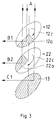
- FIG. 3 differs from that of FIGS. 1 and 2 essentially only in that the full beam is divided into three partial beams B1, B2, C1 by means of a third deflecting mirror 13.
- a first and a second deflecting mirror 12, 22 rotate synchronously and their mirror surfaces 12a, 22a and windows 12c, 22c are arranged in such a way that a partial beam through the window 12c of the first deflecting mirror 12 onto the mirror surface 22a of the second deflecting mirror 22 and A partial beam falls on the last deflecting mirror 13 both through the window 12c of the first deflecting mirror 12 and through the window 22c of the second deflecting mirror 22.
- last deflecting mirror 13 is formed over the entire surface and stationary or synchronously with the surface and with a full or partial surface on which the partial beam falling through the windows 12c and 22c of the first and second deflecting mirrors 12, 22 falls.
- the last deflecting mirror 13 ensures that the third partial beam C1 is also directed parallel to the other partial beams B1, B2.
Landscapes
- Physics & Mathematics (AREA)
- Optics & Photonics (AREA)
- General Physics & Mathematics (AREA)
- Engineering & Computer Science (AREA)
- Plasma & Fusion (AREA)
- Mechanical Engineering (AREA)
- Mechanical Light Control Or Optical Switches (AREA)
- Mounting And Adjusting Of Optical Elements (AREA)
- Lasers (AREA)
Applications Claiming Priority (2)
| Application Number | Priority Date | Filing Date | Title |
|---|---|---|---|
| DE4235165 | 1992-10-19 | ||
| DE4235165A DE4235165C2 (de) | 1992-10-19 | 1992-10-19 | Optischer Strahlteiler, insbesondere für einen Laserstrahl |
Publications (1)
| Publication Number | Publication Date |
|---|---|
| EP0593961A1 true EP0593961A1 (fr) | 1994-04-27 |
Family
ID=6470783
Family Applications (1)
| Application Number | Title | Priority Date | Filing Date |
|---|---|---|---|
| EP93115883A Withdrawn EP0593961A1 (fr) | 1992-10-19 | 1993-10-01 | Séparateur de faisceaux optique spécialement pour un faisceau laser |
Country Status (4)
| Country | Link |
|---|---|
| US (1) | US5394270A (fr) |
| EP (1) | EP0593961A1 (fr) |
| JP (1) | JPH06202038A (fr) |
| DE (1) | DE4235165C2 (fr) |
Families Citing this family (10)
| Publication number | Priority date | Publication date | Assignee | Title |
|---|---|---|---|---|
| DE4324938C2 (de) * | 1993-07-24 | 1997-02-06 | Thyssen Stahl Ag | Schneid- und Schweißvorrichtung zum stumpfen Aneinanderschweißen der Enden von vor- und nachlaufenden Metallbändern sowie Verfahren zum Schneiden und Stumpfschweißen von Bandenden unter Verwendung der Schneid- und Schweißvorrichtung |
| CA2135038C (fr) * | 1994-11-03 | 2002-01-22 | Bob Bishop | Methode et appareillage pour le traitement et la manipulation automatiques de feuilles de metal vierges, soudees a la molette par ecrasement |
| JP3468660B2 (ja) * | 1997-03-27 | 2003-11-17 | 三菱電機株式会社 | レーザビーム分岐装置 |
| US5948291A (en) * | 1997-04-29 | 1999-09-07 | General Scanning, Inc. | Laser beam distributor and computer program for controlling the same |
| DE19833368C1 (de) * | 1998-07-24 | 2000-02-17 | Schott Glas | Verfahren und Vorrichtung zur Bearbeitung von Bauteilen aus sprödbrüchigen Werkstoffen |
| US6542304B2 (en) | 1999-05-17 | 2003-04-01 | Toolz, Ltd. | Laser beam device with apertured reflective element |
| DE10043727C2 (de) * | 2000-09-05 | 2002-11-07 | Raylase Ag | Ablenkeinheit zur Lenkung eines Laserstrahls und Laserscanner |
| US6434284B1 (en) * | 2000-12-07 | 2002-08-13 | Corning Incorporated | Beam converter for enhancing brightness of polarized light sources |
| DE10128965A1 (de) * | 2001-06-15 | 2003-01-09 | Leica Microsystems | Präzisionsgehalterter Kippspiegel für optische Geräte |
| US8320426B2 (en) * | 2008-12-31 | 2012-11-27 | Ipg Photonics Corporation | Apparatus for selectively distributing energy from a laser beam |
Citations (4)
| Publication number | Priority date | Publication date | Assignee | Title |
|---|---|---|---|---|
| GB1593268A (en) * | 1977-10-03 | 1981-07-15 | Boc Ltd | Methods of and apparatus for effecting localised heating of a workpiece |
| JPS6167591A (ja) * | 1984-09-12 | 1986-04-07 | Toshiba Corp | レ−ザ加工機 |
| EP0229194A1 (fr) * | 1985-11-18 | 1987-07-22 | Matsushita Electric Industrial Co., Ltd. | Appareil de traitement au rayon laser |
| US5113055A (en) * | 1989-10-25 | 1992-05-12 | Matsushita Electric Industrial Co., Ltd. | Laser beam optical system and laser beam machining method using the same |
Family Cites Families (7)
| Publication number | Priority date | Publication date | Assignee | Title |
|---|---|---|---|---|
| CH237564A (fr) * | 1943-03-16 | 1945-04-30 | Genevoise Instr Physique | Miroir pour l'éclairage épiscopique d'une surface. |
| DE1291533B (de) * | 1966-02-25 | 1969-03-27 | Zeiss Carl Fa | Vorrichtung zur Trennung und Wiedervereinigung optischer Strahlung |
| US4087162A (en) * | 1974-12-18 | 1978-05-02 | General Dynamics Corporation | Full power optical system with displaced beam parts |
| FR2437008B1 (fr) * | 1978-09-20 | 1985-06-28 | Philip Morris Inc | Appareil de production de faisceaux lumineux pulses |
| EP0059025B1 (fr) * | 1981-02-24 | 1985-06-12 | The Commonwealth Of Australia | Système optique pour un spectrophotomètre |
| US4478477A (en) * | 1982-06-16 | 1984-10-23 | Minnesota Mining And Manufacturing Company | Electrical wire connector holder |
| US4878747A (en) * | 1985-03-01 | 1989-11-07 | Spectra-Tech, Inc. | Aperture image beam splitter |
-
1992
- 1992-10-19 DE DE4235165A patent/DE4235165C2/de not_active Expired - Fee Related
-
1993
- 1993-10-01 EP EP93115883A patent/EP0593961A1/fr not_active Withdrawn
- 1993-10-13 US US08/135,905 patent/US5394270A/en not_active Expired - Fee Related
- 1993-10-19 JP JP5260956A patent/JPH06202038A/ja active Pending
Patent Citations (4)
| Publication number | Priority date | Publication date | Assignee | Title |
|---|---|---|---|---|
| GB1593268A (en) * | 1977-10-03 | 1981-07-15 | Boc Ltd | Methods of and apparatus for effecting localised heating of a workpiece |
| JPS6167591A (ja) * | 1984-09-12 | 1986-04-07 | Toshiba Corp | レ−ザ加工機 |
| EP0229194A1 (fr) * | 1985-11-18 | 1987-07-22 | Matsushita Electric Industrial Co., Ltd. | Appareil de traitement au rayon laser |
| US5113055A (en) * | 1989-10-25 | 1992-05-12 | Matsushita Electric Industrial Co., Ltd. | Laser beam optical system and laser beam machining method using the same |
Non-Patent Citations (1)
| Title |
|---|
| PATENT ABSTRACTS OF JAPAN vol. 10, no. 234 (M - 507)<2290> 14 August 1986 (1986-08-14) * |
Also Published As
| Publication number | Publication date |
|---|---|
| JPH06202038A (ja) | 1994-07-22 |
| DE4235165C2 (de) | 1995-01-19 |
| DE4235165A1 (de) | 1994-04-21 |
| US5394270A (en) | 1995-02-28 |
Similar Documents
| Publication | Publication Date | Title |
|---|---|---|
| DE2918283C2 (de) | Gerät zur Substratbehandlung mit einem Drehspiegel od. dgl. | |
| DE2719275C2 (fr) | ||
| DE2446800A1 (de) | Niveliereinrichtung, insbesondere fuer bauzwecke | |
| EP0389033A2 (fr) | Dispositif pour la génération d'une radiation X ou gamma à faible section et position variable | |
| EP0593961A1 (fr) | Séparateur de faisceaux optique spécialement pour un faisceau laser | |
| DE3329040A1 (de) | Verfahren und einrichtung zur lichtstrahlabtastung | |
| EP1119437B1 (fr) | Dispositif pour traiter un substrat au moyen d'un rayonnement laser | |
| DE2922976C2 (de) | Vorrichtung zur Erzeugung einer Matrix von Perforationen in einer sich mit konstanter Geschwindigkeit bewegenden Materialbahn mittels einer Anzahl gepulster Laserstrahlen | |
| DE2264173A1 (de) | Lichtstrahl-ablenkungssystem | |
| WO2003039803A2 (fr) | Dispositif de traitement de substrat au moyen d'un rayonnement laser | |
| DE2835136A1 (de) | Solarelement sowie verfahren und vorrichtung zur herstellung desselben mittels ionenimplantation | |
| DE3431067C2 (fr) | ||
| EP1308235A1 (fr) | Méthode et dispositif de commande de l'énergie d'un faisceau laser | |
| DE3728660A1 (de) | Geraet zur substratbehandlung, insbesondere zum perforieren von papier | |
| DE4324938C2 (de) | Schneid- und Schweißvorrichtung zum stumpfen Aneinanderschweißen der Enden von vor- und nachlaufenden Metallbändern sowie Verfahren zum Schneiden und Stumpfschweißen von Bandenden unter Verwendung der Schneid- und Schweißvorrichtung | |
| DE3209879A1 (de) | Verfahren zur herstellung einer hochglaenzenden facette und fraeser zur durchfuehrung des verfahrens | |
| EP0536683B1 (fr) | Appareil de guidage d'un rayon laser | |
| DE2042229C3 (de) | Mehrstufige, steuerbare Lichtstrahlablenkvorrichtung | |
| DE4120905A1 (de) | Fokussier- und ablenkeinrichtung fuer einen laserstrahl zur bearbeitung von werkstuecken | |
| DE4219102C2 (de) | Strahlablenker | |
| DE1547344C3 (de) | Elektro-optische Abtastvorrichtung | |
| EP1008690A2 (fr) | Procédé et dispositif pour la fabrication d' une bande de papier | |
| DE2211597C3 (de) | Einrichtung zum Freihalten des Strahlwegs und der unmittelbaren Umgebung des Strahlwegs eines Strahls einer Energiestrahl-Materialbearbeitungsmaschine von störender Materie | |
| WO2003009047A2 (fr) | Dispositif de deflexion de faisceau laser | |
| DE10154363C1 (de) | Verfahren und Vorrichtung zur Steuerung der Laserstrahlenergie eines Laserstrahls |
Legal Events
| Date | Code | Title | Description |
|---|---|---|---|
| PUAI | Public reference made under article 153(3) epc to a published international application that has entered the european phase |
Free format text: ORIGINAL CODE: 0009012 |
|
| AK | Designated contracting states |
Kind code of ref document: A1 Designated state(s): AT BE CH DE ES FR GB GR IT LI LU NL SE |
|
| 17P | Request for examination filed |
Effective date: 19940707 |
|
| 17Q | First examination report despatched |
Effective date: 19941216 |
|
| STAA | Information on the status of an ep patent application or granted ep patent |
Free format text: STATUS: THE APPLICATION IS DEEMED TO BE WITHDRAWN |
|
| 18D | Application deemed to be withdrawn |
Effective date: 19950913 |