EP0064477A1 - Procédé et dispositif pour localiser des détonations - Google Patents
Procédé et dispositif pour localiser des détonations Download PDFInfo
- Publication number
- EP0064477A1 EP0064477A1 EP82810158A EP82810158A EP0064477A1 EP 0064477 A1 EP0064477 A1 EP 0064477A1 EP 82810158 A EP82810158 A EP 82810158A EP 82810158 A EP82810158 A EP 82810158A EP 0064477 A1 EP0064477 A1 EP 0064477A1
- Authority
- EP
- European Patent Office
- Prior art keywords
- sound
- measuring point
- time
- point
- data
- Prior art date
- Legal status (The legal status is an assumption and is not a legal conclusion. Google has not performed a legal analysis and makes no representation as to the accuracy of the status listed.)
- Granted
Links
Images

Classifications
-
- G—PHYSICS
- G01—MEASURING; TESTING
- G01S—RADIO DIRECTION-FINDING; RADIO NAVIGATION; DETERMINING DISTANCE OR VELOCITY BY USE OF RADIO WAVES; LOCATING OR PRESENCE-DETECTING BY USE OF THE REFLECTION OR RERADIATION OF RADIO WAVES; ANALOGOUS ARRANGEMENTS USING OTHER WAVES
- G01S5/00—Position-fixing by co-ordinating two or more direction or position line determinations; Position-fixing by co-ordinating two or more distance determinations
- G01S5/18—Position-fixing by co-ordinating two or more direction or position line determinations; Position-fixing by co-ordinating two or more distance determinations using ultrasonic, sonic, or infrasonic waves
- G01S5/20—Position of source determined by a plurality of spaced direction-finders
-
- F—MECHANICAL ENGINEERING; LIGHTING; HEATING; WEAPONS; BLASTING
- F41—WEAPONS
- F41G—WEAPON SIGHTS; AIMING
- F41G3/00—Aiming or laying means
- F41G3/14—Indirect aiming means
- F41G3/147—Indirect aiming means based on detection of a firing weapon
Definitions
- the invention relates to a method for locating bangs and to a system for performing this method.
- a number of microphones are arranged on a basis of 8 to 14 km in length, which is arranged as perpendicular to the expected direction of sound as possible, so that there is usually a distance of 1 to 3 km between the individual microphones.
- each microphone has to be measured very precisely in terms of coordinates, since direct mutual measurement is not possible and a coordinate-related error of at most +/- 1 meter may exist, so that there are intolerable evaluation errors.
- This means that one of the main problems with the construction of location systems is to measure the various measuring points quickly enough with the required accuracy. In very few cases, the topographically precisely measured points are available, and the personnel and time required are enormous.
- the present invention has for its object to simplify the formation of a geometric location for sound location without sacrificing accuracy and to solve the requirement that only a single or very few bangs or sound sources in the same period re registered sound pressure vibrations at the various measuring points.
- the invention also relates to a plant for carrying out this method.
- the system according to the invention has the features specified in claim 12.
- three microphones M1, M2 and M3 are arranged, in fact relatively, ie in comparison to the radius of sound propagation, close side by side in the corner points of a horizontal equilateral triangle, the side lengths of which are 5 to 30 m.
- the deviations from these target distances should be less than 1.5 cm.
- the orientation of this particular arrangement of the three microphones M1, M2, M3 with respect to the north direction should be accurate to at least 0.5 artillery per mille.
- the three microphones M1, M2, M3 are connected to an analog-to-digital converter AD, the digital output signals of which are fed to a microprocessor MP.
- the microprocessor MP is designed and programmed, regardless of the measured values, to a different one of several, preferably identical measuring points from the microphone signals generated by the incoming sound pressure vibrations of a bang or the output signals of the analog-digital converter AD for the bang in question and a direction of sound incidence determine.
- a data transmission device or a modem MD takes over the digital information of the microprocessor MP regarding sound incidence time and sound incidence direction and converts it into modulated AC signals. The latter are transmitted either via a radio device FK or via a wire line DR to an evaluation point AS to be explained with reference to FIG. 2.
- the signal from the microphone closest to the point of origin of the sound pressure oscillations activates the measuring point MS, ie a storage and computing process in the microprocessor MP.
- the sound pressure vibration signals arriving from the three microphones M1, M2, M3 are stored in the microprocessor MP, taking into account their temporal differences, the exact time of arrival of the sound pressure vibrations being recorded on the microphone causing the activation, for example the microphone M1.
- the microprocessor then creates a congruence with the measured value of the microphone Ml by shifting the measured values of the further microphones M2 and M3, so that the exact time differences of the arrival of the sound pressure vibrations of the bang on the microphones Ml, M2, M3 of the measuring point MS are determined.
- the microprocessor MP uses a simple, known trigonometric computing program to calculate the direction of sound r in the center or center of gravity S with the coordinates x and y of the measuring point MS and thus a geometric location.
- the direction of sound incidence r, the exact time of the sound incident on the microphone M1 and the designation of the measuring point MS, for example the coordinates x and y mentioned, are transmitted to the evaluation point AS as a data record either via the radio device FK or the wire line DR. Additional measurements can be added to this data record to be transmitted values are added, for example data on the wind strength and wind direction prevailing at the time of the arrival of the sound pressure oscillations at the measuring point MS.
- Corresponding measured values are obtained with the help of a weather station WS and fed to the microprocessor MP via a separation point IF (interface). Furthermore, information about the classification of the incoming sound pressure vibrations according to the presumed caliber of a gun producing the bang can be added to the data record to be transmitted in coded form, corresponding electronic devices for analyzing and classifying the sound vibrations not being shown in FIG. 1.
- the microphones M1, M2, M3 are arranged at short mutual distances of just a few meters means that an incoming sound pressure oscillation, such as that generated by a firing gun, is present in the same form on all these microphones . This makes it possible to determine the time differences of the arrival of the sound pressure vibrations at the various microphones with high accuracy, for which purpose the electronic circuits contained in a microprocessor in a known manner are the suitable means with regard to temporal resolution.
- a further microphone (not shown), which is also connected to the microprocessor MP, can be attached above the microphones M1, M2, M3 of the measuring point MS at a height of 2 to 10 m.
- the signal from this further microphone if it registers incoming sound pressure vibrations earlier than the other microphones M1, M2 and M3, causes an interruption in the evaluation of these sound pressure vibrations in the microprocessor MP and deletes the data stored in this regard.
- a system for locating bangs has several, ie at least two measuring points, as is shown, for example, by the 1 have been explained, as well as an evaluation point in which the data records transmitted by the measuring points are evaluated.
- Such a system with three measuring points MS1, MS2 and MS3 is shown schematically in FIG. 2, wherein each of these measuring points can be designed according to FIG. 1 and each contains three microphones M1, M2, M3.
- each measuring point MS1, MS2, MS3, which has a corresponding center of gravity S1, S2, S3 with the coordinates xl, yl or x2, y2 or x3, y3, a sound incidence direction rl or r2 or r3 and the corresponding sound incidence time are determined and transmitted as a data record by radio or wire to the evaluation point AS.
- the sound origin SO is determined in the first place from the intersection points of the sound incidence directions rl, r2 and r3, the correlated sound incidence times and the coordinates of the focus points S1, S2, S3.
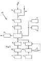
- the basic structure of an evaluation point for achieving different types of evaluation results is shown schematically in FIG. 3.
- the transmitted data sets are received by a radio device FK or via the wire line DR and fed to a data transmission device or a modem MD, which converts the received modulated AC signals into digital information signals.
- a separation place IF (interface) to the computer MD connected mini-computer MC automatically calculates all sound generation locations, e.g. their coordinates, based on the data records received and introduces them together with the associated, calculated times of sound generation, i.e. the bangs, in chronological order in a protocol unit PK, where these calculated pop-up data are stored, for example, in printed form.
- a classification of the registered bangs according to the nature of their course can be carried out and stored, for which purpose a schematically represented device KF is provided.
- a first screen unit BS1 which is provided with a keyboard T1 is connected to the mini computer MC via a corresponding separation point IF (interface).
- IF separation point
- the minicomputer MC is designed in such a way that the evaluation of the data received by the various measuring points MS1, MS2, MS3 takes place in an orderly manner according to overlapping time segments and adjacent fields of the area to be monitored.
- a time period can be 1 to 10 seconds, the overlap between two time periods being between 0.1 and 2 seconds.
- the terrain sections to be monitored are, for example, divided into 3 to 24 approximately rectangular fields.
- the minicomputer MC calculates whether there is approximately the same sound generation time in this field for more than one measuring point. If there is approximately the same time of sound generation, as already mentioned, the coordinates of the intersection of the relevant directions of incidence are fed together with the time of sound generation to the screen unit BS1 and also to the protocol unit PK.
- an IF interface
- the minicomputer MC connected and provided with a keyboard T2 screen unit BS2 is provided, on which not only sound generation locations can be displayed in certain terrain sections selected by means of the keyboard T2, but also specific sound generation locations on the screen of the display unit BS2 by means of a light pen LS in a manner known per se can be selected.
- the signal generated accordingly by the light pen LS is fed back to the minicomputer MC and, in particular, allows the calculated and sampled sound generation coordinates to be generated during a period of time previously determined by actuating the keyboard T2 and from a terrain section previously determined by actuating the keyboard T2, for example the effective range of own, far-reaching batteries can be located, transmitted directly via a target coordinate unit ZK to your own fire control system.
- the data records transmitted to the evaluation point are, if necessary, with additional information, e.g. regarding wind strength, wind direction and type of sound pressure vibrations.
- additional information e.g. regarding wind strength, wind direction and type of sound pressure vibrations.
Priority Applications (1)
| Application Number | Priority Date | Filing Date | Title |
|---|---|---|---|
| AT82810158T ATE24776T1 (de) | 1981-04-23 | 1982-04-14 | Verfahren und anlage zur ortung von knallen. |
Applications Claiming Priority (2)
| Application Number | Priority Date | Filing Date | Title |
|---|---|---|---|
| CH2666/81 | 1981-04-23 | ||
| CH266681 | 1981-04-23 |
Publications (2)
| Publication Number | Publication Date |
|---|---|
| EP0064477A1 true EP0064477A1 (fr) | 1982-11-10 |
| EP0064477B1 EP0064477B1 (fr) | 1987-01-07 |
Family
ID=4238840
Family Applications (1)
| Application Number | Title | Priority Date | Filing Date |
|---|---|---|---|
| EP82810158A Expired EP0064477B1 (fr) | 1981-04-23 | 1982-04-14 | Procédé et dispositif pour localiser des détonations |
Country Status (3)
| Country | Link |
|---|---|
| EP (1) | EP0064477B1 (fr) |
| AT (1) | ATE24776T1 (fr) |
| DE (1) | DE3275016D1 (fr) |
Cited By (12)
| Publication number | Priority date | Publication date | Assignee | Title |
|---|---|---|---|---|
| DE3524753A1 (de) * | 1985-07-11 | 1987-01-29 | Standard Elektrik Lorenz Ag | Schallmesssystem |
| WO1987002144A1 (fr) * | 1985-10-05 | 1987-04-09 | Plessey Overseas Limited | Procede et dispositif de localisation d'une source sonore |
| GB2181240A (en) * | 1985-10-05 | 1987-04-15 | Plessey Co Plc | A method of detecting sound impulses |
| GB2181239A (en) * | 1985-10-05 | 1987-04-15 | Plessey Co Plc | A method of detecting sound impulses |
| WO1987005706A1 (fr) * | 1986-03-12 | 1987-09-24 | Ms Instruments Plc | Appareil et procede de mesure de positions |
| EP0642032A2 (fr) * | 1993-09-08 | 1995-03-08 | ISHIKAWA MANUFACTURING CO., Ltd. | Système de détermination de source sonore |
| EP0778952A1 (fr) * | 1994-08-30 | 1997-06-18 | Aai Corporation | Determination de l'origine d'un projectile |
| DE19707651A1 (de) * | 1997-02-26 | 1998-08-27 | Itt Mfg Enterprises Inc | Ultraschall-Abstandsmeßsystem mit im Zeitmultiplex übertragenen digitalen Meßsignalen |
| US6563763B2 (en) | 2001-04-03 | 2003-05-13 | Aai Corporation | Method and system for correcting for curvature in determining the trajectory of a projectile |
| EP1318619A1 (fr) * | 2001-12-06 | 2003-06-11 | Didier Le Boulc'h | Marqueur temporel optique-radio et procédé de localisation de sources d'ondes optiques par des signaux radio |
| GB2399169A (en) * | 2003-02-06 | 2004-09-08 | Reef Man Internat Ltd | Detecting the location of an underwater explosion |
| WO2016087115A1 (fr) * | 2014-12-05 | 2016-06-09 | Thyssenkrupp Marine Systems Gmbh | Système et procédé de localisation et de lutte contre des menaces, notamment dans des positions de menace asymétriques |
Families Citing this family (1)
| Publication number | Priority date | Publication date | Assignee | Title |
|---|---|---|---|---|
| DE102012021053B4 (de) * | 2012-10-25 | 2014-12-04 | Iav Gmbh Ingenieurgesellschaft Auto Und Verkehr | Klopfortbestimmungsverfahren und Klopfortbestimmungsvorrichtung für Brennkraftmaschinen |
Citations (7)
| Publication number | Priority date | Publication date | Assignee | Title |
|---|---|---|---|---|
| FR2121450A7 (fr) * | 1969-05-30 | 1972-08-25 | Fiogere Marius | |
| US3707699A (en) * | 1970-08-07 | 1972-12-26 | Del Mar Eng Lab | Remote scoring system for bombing or rocket range |
| FR2231013A1 (en) * | 1973-05-22 | 1974-12-20 | Tech Radioelect Electro Fs | Identification of low flying aircraft by sound - involves eliminating doppler ambiguity by variable time sampling |
| US3984803A (en) * | 1967-09-06 | 1976-10-05 | The United States Of America As Represented By The United States Energy Research And Development Administration | Seismic intrusion detector system |
| EP0019428A1 (fr) * | 1979-05-10 | 1980-11-26 | Australasian Training Aids (Pty) Ltd. | Dispositif de localisation d'un projectile |
| DE2922429B2 (de) * | 1979-06-01 | 1981-03-26 | Messerschmitt-Bölkow-Blohm GmbH, 8000 München | Peilanordnung |
| US4305142A (en) * | 1980-01-18 | 1981-12-08 | Springer Barry R | Ballistic impact sensing and display system |
Family Cites Families (1)
| Publication number | Priority date | Publication date | Assignee | Title |
|---|---|---|---|---|
| DE703381C (de) * | 1935-03-14 | 1941-03-07 | Aeg | Verfahren zur Ermittlung der Richtung bzw. des Ortes einer Schallquelle, insbesondere eines Geschuetzes |
-
1982
- 1982-04-14 AT AT82810158T patent/ATE24776T1/de active
- 1982-04-14 DE DE8282810158T patent/DE3275016D1/de not_active Expired
- 1982-04-14 EP EP82810158A patent/EP0064477B1/fr not_active Expired
Patent Citations (7)
| Publication number | Priority date | Publication date | Assignee | Title |
|---|---|---|---|---|
| US3984803A (en) * | 1967-09-06 | 1976-10-05 | The United States Of America As Represented By The United States Energy Research And Development Administration | Seismic intrusion detector system |
| FR2121450A7 (fr) * | 1969-05-30 | 1972-08-25 | Fiogere Marius | |
| US3707699A (en) * | 1970-08-07 | 1972-12-26 | Del Mar Eng Lab | Remote scoring system for bombing or rocket range |
| FR2231013A1 (en) * | 1973-05-22 | 1974-12-20 | Tech Radioelect Electro Fs | Identification of low flying aircraft by sound - involves eliminating doppler ambiguity by variable time sampling |
| EP0019428A1 (fr) * | 1979-05-10 | 1980-11-26 | Australasian Training Aids (Pty) Ltd. | Dispositif de localisation d'un projectile |
| DE2922429B2 (de) * | 1979-06-01 | 1981-03-26 | Messerschmitt-Bölkow-Blohm GmbH, 8000 München | Peilanordnung |
| US4305142A (en) * | 1980-01-18 | 1981-12-08 | Springer Barry R | Ballistic impact sensing and display system |
Cited By (18)
| Publication number | Priority date | Publication date | Assignee | Title |
|---|---|---|---|---|
| DE3524753A1 (de) * | 1985-07-11 | 1987-01-29 | Standard Elektrik Lorenz Ag | Schallmesssystem |
| WO1987002144A1 (fr) * | 1985-10-05 | 1987-04-09 | Plessey Overseas Limited | Procede et dispositif de localisation d'une source sonore |
| GB2181240A (en) * | 1985-10-05 | 1987-04-15 | Plessey Co Plc | A method of detecting sound impulses |
| GB2181238A (en) * | 1985-10-05 | 1987-04-15 | Plessey Co Plc | Automatically locating the position of a sound source |
| GB2181239A (en) * | 1985-10-05 | 1987-04-15 | Plessey Co Plc | A method of detecting sound impulses |
| GB2181240B (en) * | 1985-10-05 | 1989-09-27 | Plessey Co Plc | Improvements in or relating to a method of detecting sound |
| WO1987005706A1 (fr) * | 1986-03-12 | 1987-09-24 | Ms Instruments Plc | Appareil et procede de mesure de positions |
| US4885725A (en) * | 1986-03-12 | 1989-12-05 | MS Instruments public limited company | Position measuring apparatus and method |
| EP0642032A2 (fr) * | 1993-09-08 | 1995-03-08 | ISHIKAWA MANUFACTURING CO., Ltd. | Système de détermination de source sonore |
| EP0642032A3 (fr) * | 1993-09-08 | 1995-11-22 | Ishikawa Manufacturing Co Ltd | Système de détermination de source sonore. |
| EP0778952A1 (fr) * | 1994-08-30 | 1997-06-18 | Aai Corporation | Determination de l'origine d'un projectile |
| EP0778952A4 (fr) * | 1994-08-30 | 1999-09-22 | Aai Corp | Determination de l'origine d'un projectile |
| DE19707651A1 (de) * | 1997-02-26 | 1998-08-27 | Itt Mfg Enterprises Inc | Ultraschall-Abstandsmeßsystem mit im Zeitmultiplex übertragenen digitalen Meßsignalen |
| US6326886B1 (en) | 1997-02-26 | 2001-12-04 | Itt Manufacturing Enterprises, Inc. | Ultrasound distance measuring system with digital measuring signals transmitted by time multiplexing |
| US6563763B2 (en) | 2001-04-03 | 2003-05-13 | Aai Corporation | Method and system for correcting for curvature in determining the trajectory of a projectile |
| EP1318619A1 (fr) * | 2001-12-06 | 2003-06-11 | Didier Le Boulc'h | Marqueur temporel optique-radio et procédé de localisation de sources d'ondes optiques par des signaux radio |
| GB2399169A (en) * | 2003-02-06 | 2004-09-08 | Reef Man Internat Ltd | Detecting the location of an underwater explosion |
| WO2016087115A1 (fr) * | 2014-12-05 | 2016-06-09 | Thyssenkrupp Marine Systems Gmbh | Système et procédé de localisation et de lutte contre des menaces, notamment dans des positions de menace asymétriques |
Also Published As
| Publication number | Publication date |
|---|---|
| ATE24776T1 (de) | 1987-01-15 |
| DE3275016D1 (en) | 1987-02-12 |
| EP0064477B1 (fr) | 1987-01-07 |
Similar Documents
| Publication | Publication Date | Title |
|---|---|---|
| DE2824800C2 (de) | Vorrichtung zum Bestimmen der Lage eines Ultraschallprüfkopfes | |
| DE2643255C2 (de) | Anordnung zur Feststellung von in einen Sicherheitsbereich gelangenden Eindringlingen | |
| DE3204874C2 (de) | Passives Verfahren zum Gewinnen von Zieldaten von einer Schallquelle | |
| EP0064477B1 (fr) | Procédé et dispositif pour localiser des détonations | |
| DE3012616C2 (de) | Flughafenüberwachungseinrichtung | |
| DE102011012601A1 (de) | Kraftmesssystem, Verfahren zum Erfassen von Kräften und Momenten an einem rotierenden Körper und Windkanal mit einem darin angeordneten und zumindest einen Propeller aufweisenden Modell mit einem Kraftmesssystem | |
| DE3000360A1 (de) | Anordnung zur ausbildung von schuetzen | |
| DE2440321C3 (de) | Vorrichtung zur automatischen Messung von Tunnel-Profilen | |
| DE2816332C3 (de) | Vorrichtung zur Identifizierung einer bewegten Schallquelle | |
| EP0268788B1 (fr) | Méthode et dispositif pour vérifier le fonctionnement d'un microphone | |
| DE2307722A1 (de) | Verfahren und geraet zur flaechenmessung ohne beruehrung | |
| EP1177438A2 (fr) | Dispositif pour essais de materiaux | |
| DE2757585B2 (de) | Einrichtung zum selbsttätigen Ausrichten eines Laserstrahls auf ein Ziel | |
| EP0232762A1 (fr) | Méthode pour déterminer acoustiquement les trajectoires de projectiles et détermination de la distance minimum projectile-cible | |
| DE3116586C2 (fr) | ||
| EP1039289A2 (fr) | Procédé et dispositif pour déterminer la vitesse et la taille des particules | |
| DE3808983A1 (de) | Vorrichtung zur erzeugung einer mehrzahl von akustischen energiespektren | |
| DE1703171A1 (de) | Treffbildanzeigegeraet fuer die Ermittlung der Durchschusspunktkoordinaten von Geschossen | |
| CH589835A5 (en) | Firing target with electronic hit evaluation - has several measuring sensors underneath target area and electronic computer for hit evaluation | |
| DE2942355A1 (de) | Vorrichtung zum erfassen des durchganges eines projektils | |
| EP0072770B1 (fr) | Procédé et dispositif pour la mesure des différences du temps de transit des impulsions ultrasonores pour la détermination des champs d'écoulement | |
| DE3517671A1 (de) | Vorrichtung zum bildpunktweisen erfassen der oberflaechengestalt eines entfernten objektes | |
| DE3702428A1 (de) | Verfahren und vorrichtung zum messtechnischen erfassen eines projektils oder teilen hiervon | |
| EP3396404A1 (fr) | Procédé de détection de la position d'objets | |
| DE3524753C2 (de) | Schallmeßsystem |
Legal Events
| Date | Code | Title | Description |
|---|---|---|---|
| PUAI | Public reference made under article 153(3) epc to a published international application that has entered the european phase |
Free format text: ORIGINAL CODE: 0009012 |
|
| AK | Designated contracting states |
Designated state(s): AT DE FR GB IT SE |
|
| 17P | Request for examination filed |
Effective date: 19830421 |
|
| ITF | It: translation for a ep patent filed |
Owner name: FUMERO BREVETTI S.N.C. |
|
| GRAA | (expected) grant |
Free format text: ORIGINAL CODE: 0009210 |
|
| AK | Designated contracting states |
Kind code of ref document: B1 Designated state(s): AT DE FR GB IT SE |
|
| REF | Corresponds to: |
Ref document number: 24776 Country of ref document: AT Date of ref document: 19870115 Kind code of ref document: T |
|
| REF | Corresponds to: |
Ref document number: 3275016 Country of ref document: DE Date of ref document: 19870212 |
|
| ET | Fr: translation filed | ||
| PLBI | Opposition filed |
Free format text: ORIGINAL CODE: 0009260 |
|
| PLBI | Opposition filed |
Free format text: ORIGINAL CODE: 0009260 |
|
| 26 | Opposition filed |
Opponent name: BUNDESREPUBLIK DEUTSCHLAND, DIESE VERTRETEN DURCH Effective date: 19871001 |
|
| 26 | Opposition filed |
Opponent name: STANDARD ELEKTRIK LORENZ AG Effective date: 19871006 |
|
| PLBN | Opposition rejected |
Free format text: ORIGINAL CODE: 0009273 |
|
| STAA | Information on the status of an ep patent application or granted ep patent |
Free format text: STATUS: OPPOSITION REJECTED |
|
| 27O | Opposition rejected |
Effective date: 19910110 |
|
| ITTA | It: last paid annual fee | ||
| EAL | Se: european patent in force in sweden |
Ref document number: 82810158.4 |
|
| PGFP | Annual fee paid to national office [announced via postgrant information from national office to epo] |
Ref country code: AT Payment date: 19960314 Year of fee payment: 15 |
|
| PG25 | Lapsed in a contracting state [announced via postgrant information from national office to epo] |
Ref country code: AT Effective date: 19970414 |
|
| REG | Reference to a national code |
Ref country code: FR Ref legal event code: TP |
|
| REG | Reference to a national code |
Ref country code: GB Ref legal event code: 732E |
|
| PGFP | Annual fee paid to national office [announced via postgrant information from national office to epo] |
Ref country code: FR Payment date: 20010312 Year of fee payment: 20 |
|
| PGFP | Annual fee paid to national office [announced via postgrant information from national office to epo] |
Ref country code: SE Payment date: 20010319 Year of fee payment: 20 Ref country code: GB Payment date: 20010319 Year of fee payment: 20 |
|
| PGFP | Annual fee paid to national office [announced via postgrant information from national office to epo] |
Ref country code: DE Payment date: 20010321 Year of fee payment: 20 |
|
| REG | Reference to a national code |
Ref country code: GB Ref legal event code: IF02 |
|
| PG25 | Lapsed in a contracting state [announced via postgrant information from national office to epo] |
Ref country code: GB Free format text: LAPSE BECAUSE OF EXPIRATION OF PROTECTION Effective date: 20020413 |
|
| REG | Reference to a national code |
Ref country code: GB Ref legal event code: PE20 Effective date: 20020413 |
|
| EUG | Se: european patent has lapsed |
Ref document number: 82810158.4 |
|
| APAH | Appeal reference modified |
Free format text: ORIGINAL CODE: EPIDOSCREFNO |