EP0064477A1 - Method and assembly to locate detonations - Google Patents
Method and assembly to locate detonations Download PDFInfo
- Publication number
- EP0064477A1 EP0064477A1 EP82810158A EP82810158A EP0064477A1 EP 0064477 A1 EP0064477 A1 EP 0064477A1 EP 82810158 A EP82810158 A EP 82810158A EP 82810158 A EP82810158 A EP 82810158A EP 0064477 A1 EP0064477 A1 EP 0064477A1
- Authority
- EP
- European Patent Office
- Prior art keywords
- sound
- measuring point
- time
- point
- data
- Prior art date
- Legal status (The legal status is an assumption and is not a legal conclusion. Google has not performed a legal analysis and makes no representation as to the accuracy of the status listed.)
- Granted
Links
Images

Classifications
-
- G—PHYSICS
- G01—MEASURING; TESTING
- G01S—RADIO DIRECTION-FINDING; RADIO NAVIGATION; DETERMINING DISTANCE OR VELOCITY BY USE OF RADIO WAVES; LOCATING OR PRESENCE-DETECTING BY USE OF THE REFLECTION OR RERADIATION OF RADIO WAVES; ANALOGOUS ARRANGEMENTS USING OTHER WAVES
- G01S5/00—Position-fixing by co-ordinating two or more direction or position line determinations; Position-fixing by co-ordinating two or more distance determinations
- G01S5/18—Position-fixing by co-ordinating two or more direction or position line determinations; Position-fixing by co-ordinating two or more distance determinations using ultrasonic, sonic, or infrasonic waves
- G01S5/20—Position of source determined by a plurality of spaced direction-finders
-
- F—MECHANICAL ENGINEERING; LIGHTING; HEATING; WEAPONS; BLASTING
- F41—WEAPONS
- F41G—WEAPON SIGHTS; AIMING
- F41G3/00—Aiming or laying means
- F41G3/14—Indirect aiming means
- F41G3/147—Indirect aiming means based on detection of a firing weapon
Definitions
- the invention relates to a method for locating bangs and to a system for performing this method.
- a number of microphones are arranged on a basis of 8 to 14 km in length, which is arranged as perpendicular to the expected direction of sound as possible, so that there is usually a distance of 1 to 3 km between the individual microphones.
- each microphone has to be measured very precisely in terms of coordinates, since direct mutual measurement is not possible and a coordinate-related error of at most +/- 1 meter may exist, so that there are intolerable evaluation errors.
- This means that one of the main problems with the construction of location systems is to measure the various measuring points quickly enough with the required accuracy. In very few cases, the topographically precisely measured points are available, and the personnel and time required are enormous.
- the present invention has for its object to simplify the formation of a geometric location for sound location without sacrificing accuracy and to solve the requirement that only a single or very few bangs or sound sources in the same period re registered sound pressure vibrations at the various measuring points.
- the invention also relates to a plant for carrying out this method.
- the system according to the invention has the features specified in claim 12.
- three microphones M1, M2 and M3 are arranged, in fact relatively, ie in comparison to the radius of sound propagation, close side by side in the corner points of a horizontal equilateral triangle, the side lengths of which are 5 to 30 m.
- the deviations from these target distances should be less than 1.5 cm.
- the orientation of this particular arrangement of the three microphones M1, M2, M3 with respect to the north direction should be accurate to at least 0.5 artillery per mille.
- the three microphones M1, M2, M3 are connected to an analog-to-digital converter AD, the digital output signals of which are fed to a microprocessor MP.
- the microprocessor MP is designed and programmed, regardless of the measured values, to a different one of several, preferably identical measuring points from the microphone signals generated by the incoming sound pressure vibrations of a bang or the output signals of the analog-digital converter AD for the bang in question and a direction of sound incidence determine.
- a data transmission device or a modem MD takes over the digital information of the microprocessor MP regarding sound incidence time and sound incidence direction and converts it into modulated AC signals. The latter are transmitted either via a radio device FK or via a wire line DR to an evaluation point AS to be explained with reference to FIG. 2.
- the signal from the microphone closest to the point of origin of the sound pressure oscillations activates the measuring point MS, ie a storage and computing process in the microprocessor MP.
- the sound pressure vibration signals arriving from the three microphones M1, M2, M3 are stored in the microprocessor MP, taking into account their temporal differences, the exact time of arrival of the sound pressure vibrations being recorded on the microphone causing the activation, for example the microphone M1.
- the microprocessor then creates a congruence with the measured value of the microphone Ml by shifting the measured values of the further microphones M2 and M3, so that the exact time differences of the arrival of the sound pressure vibrations of the bang on the microphones Ml, M2, M3 of the measuring point MS are determined.
- the microprocessor MP uses a simple, known trigonometric computing program to calculate the direction of sound r in the center or center of gravity S with the coordinates x and y of the measuring point MS and thus a geometric location.
- the direction of sound incidence r, the exact time of the sound incident on the microphone M1 and the designation of the measuring point MS, for example the coordinates x and y mentioned, are transmitted to the evaluation point AS as a data record either via the radio device FK or the wire line DR. Additional measurements can be added to this data record to be transmitted values are added, for example data on the wind strength and wind direction prevailing at the time of the arrival of the sound pressure oscillations at the measuring point MS.
- Corresponding measured values are obtained with the help of a weather station WS and fed to the microprocessor MP via a separation point IF (interface). Furthermore, information about the classification of the incoming sound pressure vibrations according to the presumed caliber of a gun producing the bang can be added to the data record to be transmitted in coded form, corresponding electronic devices for analyzing and classifying the sound vibrations not being shown in FIG. 1.
- the microphones M1, M2, M3 are arranged at short mutual distances of just a few meters means that an incoming sound pressure oscillation, such as that generated by a firing gun, is present in the same form on all these microphones . This makes it possible to determine the time differences of the arrival of the sound pressure vibrations at the various microphones with high accuracy, for which purpose the electronic circuits contained in a microprocessor in a known manner are the suitable means with regard to temporal resolution.
- a further microphone (not shown), which is also connected to the microprocessor MP, can be attached above the microphones M1, M2, M3 of the measuring point MS at a height of 2 to 10 m.
- the signal from this further microphone if it registers incoming sound pressure vibrations earlier than the other microphones M1, M2 and M3, causes an interruption in the evaluation of these sound pressure vibrations in the microprocessor MP and deletes the data stored in this regard.
- a system for locating bangs has several, ie at least two measuring points, as is shown, for example, by the 1 have been explained, as well as an evaluation point in which the data records transmitted by the measuring points are evaluated.
- Such a system with three measuring points MS1, MS2 and MS3 is shown schematically in FIG. 2, wherein each of these measuring points can be designed according to FIG. 1 and each contains three microphones M1, M2, M3.
- each measuring point MS1, MS2, MS3, which has a corresponding center of gravity S1, S2, S3 with the coordinates xl, yl or x2, y2 or x3, y3, a sound incidence direction rl or r2 or r3 and the corresponding sound incidence time are determined and transmitted as a data record by radio or wire to the evaluation point AS.
- the sound origin SO is determined in the first place from the intersection points of the sound incidence directions rl, r2 and r3, the correlated sound incidence times and the coordinates of the focus points S1, S2, S3.
- the basic structure of an evaluation point for achieving different types of evaluation results is shown schematically in FIG. 3.
- the transmitted data sets are received by a radio device FK or via the wire line DR and fed to a data transmission device or a modem MD, which converts the received modulated AC signals into digital information signals.
- a separation place IF (interface) to the computer MD connected mini-computer MC automatically calculates all sound generation locations, e.g. their coordinates, based on the data records received and introduces them together with the associated, calculated times of sound generation, i.e. the bangs, in chronological order in a protocol unit PK, where these calculated pop-up data are stored, for example, in printed form.
- a classification of the registered bangs according to the nature of their course can be carried out and stored, for which purpose a schematically represented device KF is provided.
- a first screen unit BS1 which is provided with a keyboard T1 is connected to the mini computer MC via a corresponding separation point IF (interface).
- IF separation point
- the minicomputer MC is designed in such a way that the evaluation of the data received by the various measuring points MS1, MS2, MS3 takes place in an orderly manner according to overlapping time segments and adjacent fields of the area to be monitored.
- a time period can be 1 to 10 seconds, the overlap between two time periods being between 0.1 and 2 seconds.
- the terrain sections to be monitored are, for example, divided into 3 to 24 approximately rectangular fields.
- the minicomputer MC calculates whether there is approximately the same sound generation time in this field for more than one measuring point. If there is approximately the same time of sound generation, as already mentioned, the coordinates of the intersection of the relevant directions of incidence are fed together with the time of sound generation to the screen unit BS1 and also to the protocol unit PK.
- an IF interface
- the minicomputer MC connected and provided with a keyboard T2 screen unit BS2 is provided, on which not only sound generation locations can be displayed in certain terrain sections selected by means of the keyboard T2, but also specific sound generation locations on the screen of the display unit BS2 by means of a light pen LS in a manner known per se can be selected.
- the signal generated accordingly by the light pen LS is fed back to the minicomputer MC and, in particular, allows the calculated and sampled sound generation coordinates to be generated during a period of time previously determined by actuating the keyboard T2 and from a terrain section previously determined by actuating the keyboard T2, for example the effective range of own, far-reaching batteries can be located, transmitted directly via a target coordinate unit ZK to your own fire control system.
- the data records transmitted to the evaluation point are, if necessary, with additional information, e.g. regarding wind strength, wind direction and type of sound pressure vibrations.
- additional information e.g. regarding wind strength, wind direction and type of sound pressure vibrations.
Abstract
Description
Die Erfindung bezieht sich auf ein Verfahren zur Ortung von Knallen sowie auf eine Anlage zur Ausführung dieses Verfahrens.The invention relates to a method for locating bangs and to a system for performing this method.
Schallortungssysteme dieser Art sind seit längerer Zeit bekannt und eingeführt. So sind insbesondere mit dem Aufkommen der elektrischen Messwertübertragung Systeme entstanden, die sich das Prinzip zu Nutze gemacht haben, dass aus Laufzeitdifferenzen des Schalles, gemessen an zwei relativ weit auseinanderliegenden Messpunkten, von diesen zwei Messpunkten aus der geometrische Ort konstruiert werden kann, auf welchem alle Punkte mit der gleichen Laufzeit-Differenz liegen. Dieser Ort ist ein Hyperbel. Gelingt es, für den gleichen Knall mindestens zwei derartige geometrische Orte aus mindestens drei Messpunkten zu konstruieren, so liegt der Knallentstehungsort auf dem Schnittpunkt dieser beiden geometrischen Orte.Sound locating systems of this type have been known and introduced for a long time. In particular, with the advent of electrical measured value transmission, systems have emerged that have taken advantage of the principle that, based on the transit time differences of the sound, measured at two relatively far apart measuring points, the geometric location on which all of these measuring points can be constructed can be constructed Points with the same transit time difference lie. This place is a hyperbole. If it is possible to construct at least two such geometric locations from at least three measuring points for the same bang, the location of the bang is at the intersection of these two geometric locations.
Viele bekannte Vorschläge, z.B. gemäss DE-PS 703381, beziehen sich darauf, die Auswertung bis zur Bildung dieses Schnittpunktes von zwei, drei oder mehreren geometrischen Orten mittels mechanischer oder elektrischer Hilfsmittel zu vereinfachen, ohne am Prinzip der Hyperbelbildung etwas zu verändern. Vereinzelt sind auch Bestrebungen ersichtlich, bei Dauergeräuschen mit spezieller Anordnung von mehreren Mikrophonen und Ausnützung der Phasenverschiebungen das Intensitätsmaximum und somit eine definierbare Schalleinfallsrichtung zu bestimmen. Dieses Verfahren ist aber nur bei Dauergeräuschen brauchbar, wie sie beispielsweise von Unterseebooten erzeugt werden.Many known proposals, for example according to DE-PS 703381, relate to the evaluation until this section is formed to simplify the point of two, three or more geometric locations by means of mechanical or electrical aids, without changing the principle of hyperbole formation. Efforts are also occasionally evident to determine the maximum intensity and thus a definable direction of sound incidence in the case of continuous noise with a special arrangement of several microphones and the use of phase shifts. However, this method can only be used for continuous noises, such as those generated by submarines.
Allen diesen Verfahren und Bestrebungen haftet der Nachteil an, dass die richtige Zuordnung der an verschiedenen Orten registrierten Druckschwingungen zum gleichen, einzumessenden Knall mit der notwendigen Sicherheit gegeben sein muss, um aus jeweils zwei weit auseinanderliegenden Messorten die entsprechenden geometrischen Orte konstruieren zu können. Diese Sicherheit ist dann nicht mehr gegeben, wenn Druckschwingungen von zwei oder mehr Entstehungsorten, welche weit auseinanderliegen können, gleichzeitig, das heisst innerhalb eines Zeitraumes von 0 bis 10 oder 20 Sekunden, an den verschiedenen Messpunkten eintreffen. Dies ist nicht nur häufig der Fall, sondern wird insbesondere bei der Artillerie und insbesondere zum Zwecke der Schalltarnung in vielen Armeen geschult und angewendet. Schalltarnung heisst in militärischen Fachkreisen dasjenige Abfeuern von Geschützen, welches es dem Gegner erschwert oder verunmöglicht, mit dem oben beschriebenen Verfahren die Feuerstellungen zu orten.All these methods and efforts have the disadvantage that the correct assignment of the pressure vibrations registered at different locations to the same bang to be measured must be given with the necessary certainty in order to be able to construct the corresponding geometric locations from two measuring locations that are far apart. This security is no longer given if pressure vibrations from two or more places of origin, which can be far apart, arrive at the different measuring points simultaneously, i.e. within a period of 0 to 10 or 20 seconds. This is not only often the case, but is also trained and used in many armies, particularly in artillery and especially for the purpose of sound camouflage. In military circles, sound camouflage means the firing of guns that it does to the enemy sword or impossible to locate the firing positions using the procedure described above.
Nach den zurzeit üblichen Verfahren werden auf einer Basis von 8 bis 14 km Länge, welche möglichst rechtwinklig zu der erwarteten Schalleinfallsrichtung angeordnet ist, eine Anzahl von Mikrophonen so angeordnet, dass üblicherweise ein Abstand von 1 bis 3 km zwischen den einzelnen Mikrophonen entsteht. Dadurch entsteht der weitere gravierende Nachteil, dass jedes Mikrophon für sich sehr genau koordinatenmässig vermessen werden muss, da ein direktes gegenseitiges Vermessen nicht möglich ist und dennoch ein koordinatenmässiger Fehler von höchstens +/- 1 Meter vorliegen darf, damit nicht untragbare Auswertefehler entstehen. Dies führt dazu, dass ein Hauptproblem beim Aufbau von Ortungssystemen darin liegt, rasch genug die verschiedenen Messpunkte mit der geforderten Genauigkeit zu vermessen. In den wenigsten Fällen sind die topographisch genau vermessenen Punkte zur Verfügung, und der personelle und der zeitliche Aufwand ist enorm.According to the currently customary methods, a number of microphones are arranged on a basis of 8 to 14 km in length, which is arranged as perpendicular to the expected direction of sound as possible, so that there is usually a distance of 1 to 3 km between the individual microphones. This creates the further serious disadvantage that each microphone has to be measured very precisely in terms of coordinates, since direct mutual measurement is not possible and a coordinate-related error of at most +/- 1 meter may exist, so that there are intolerable evaluation errors. This means that one of the main problems with the construction of location systems is to measure the various measuring points quickly enough with the required accuracy. In very few cases, the topographically precisely measured points are available, and the personnel and time required are enormous.
Der vorliegenden Erfindung liegt die Aufgabe zugrunde, die Bildung eines geometrischen Ortes für die Schallortung ohne Einbusse an Genauigkeit zu vereinfachen und von der Voraussetzung zu lösen, dass nur ein einziger oder ganz wenige Knalle bzw. Schallentstehungsorte im gleichen Zeitraum zu registrierten Schalldruckschwingungen an den verschiedenen Messstellen führen.The present invention has for its object to simplify the formation of a geometric location for sound location without sacrificing accuracy and to solve the requirement that only a single or very few bangs or sound sources in the same period re registered sound pressure vibrations at the various measuring points.
Erfindungsgemäss wird diese Aufgabe durch das Verfahren der eingangs genannten Art gelöst, das die im kennzeichnenden Teil des Patentanspruchs 1 angeführten Merkmale aufweist.According to the invention, this object is achieved by the method of the type mentioned at the outset, which has the features stated in the characterizing part of patent claim 1.
Die Erfindung bezieht sich auch auf eine Anlage zur Ausführung dieses Verfahrens. Die erfindungsgemässe Anlage weist die im Patentanspruch 12 angeführten Merkmale auf.The invention also relates to a plant for carrying out this method. The system according to the invention has the features specified in claim 12.
Ausführungsbeispiele der Erfindungsgegenstände werden nachfolgend anhand der Zeichnungen erläutert. Es zeigen:
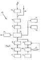
- Fig. 1 ein Blockschema einer Messstelle mit drei Mikrophonen,
- Fig. 2 eine schematische Darstellung einer Anlage mit drei Messstellen,
- Fig. 3 ein Blockschema einer Auswertestelle.
- 1 is a block diagram of a measuring point with three microphones,
- 2 shows a schematic representation of a system with three measuring points,
- 3 shows a block diagram of an evaluation point.
Bei der in Fig. 1 schematisch dargestellten Messstelle MS sind drei Mikrophone M1, M2 und M3 angeordnet, und zwar verhältnismässig, d.h. im Vergleich zum Schallausbreitungsradius, nahe beieinanderliegend in den Eckpunkten eines horizontalen gleichseitigen Dreiecks, dessen Seitenlängen 5 bis 30 m betragen. Die Abweichungen von diesen Sollabständen soll weniger als 1,5 cm betragen. Die Orientierung dieser bestimmten Anordnung der drei Mikrophone M1, M2, M3 in bezug auf die Nordrichtung soll auf mindestens 0,5 Artilleriepromille genau erfolgen. Die drei Mikrophone Ml, M2, M3 sind an einen Analog-Digitalumsetzer AD angeschlossen, dessen digitale Ausgangssignale einem Mikroprozessor MP zugeführt sind.At the measuring point MS shown schematically in FIG. 1, three microphones M1, M2 and M3 are arranged, in fact relatively, ie in comparison to the radius of sound propagation, close side by side in the corner points of a horizontal equilateral triangle, the side lengths of which are 5 to 30 m. The deviations from these target distances should be less than 1.5 cm. The orientation of this particular arrangement of the three microphones M1, M2, M3 with respect to the north direction should be accurate to at least 0.5 artillery per mille. The three microphones M1, M2, M3 are connected to an analog-to-digital converter AD, the digital output signals of which are fed to a microprocessor MP.
Der Mikroprozessor MP ist dazu ausgebildet und programmiert, unabhängig von den Messwerten einer anderen von mehreren, vorzugsweise gleichartigen Messstellen aus den durch die eintreffenden Schalldruckschwingungen eines Knalles erzeugten Mikrophonsignalen bzw. den Ausgangssignalen des Analog-Digitalumsetzers AD für den betreffenden Knall eine Schalleinfallszeit und eine Schalleinfallsrichtung zu bestimmen. Eine Datenübertragungseinrichtung oder ein Modem MD übernimmt die digitalen Informationen des Mikroprozessors MP betreffend Schalleinfallszeit und Schalleinfallsrichtung und wandelt sie in modulierte Wechselstromsignale um. Die letzteren werden entweder über ein Funkgerät FK oder über eine Drahtleitung DR an eine anhand der Fig. 2 noch zu erläuternde Auswertestelle AS übermittelt.For this purpose, the microprocessor MP is designed and programmed, regardless of the measured values, to a different one of several, preferably identical measuring points from the microphone signals generated by the incoming sound pressure vibrations of a bang or the output signals of the analog-digital converter AD for the bang in question and a direction of sound incidence determine. A data transmission device or a modem MD takes over the digital information of the microprocessor MP regarding sound incidence time and sound incidence direction and converts it into modulated AC signals. The latter are transmitted either via a radio device FK or via a wire line DR to an evaluation point AS to be explained with reference to FIG. 2.
Im Mikroprozessor MP aktiviert das Signal des dem Entstehungsort der Schalldruckschwingungen nächstgelegenen Mikrophons die Messstelle MS, d.h. einen Speicher- und Rechenvorgang im Mikroprozessor MP. Im Mikroprozessor MP werden nach dieser Aktivierung die von den drei Mikrophonen M1, M2, M3 eintreffenden Schalldruckschwingungssignale unter Berücksichtigung ihrer zeitlichen Differenzen gespeichert, wobei die genaue Uhrzeit des Eintreffens der Schalldruckschwingungen an dem die Aktivierung bewirkenden Mikrophon, z.B. dem Mikrophon M1, festgehalten wird. Im Mikroprozessor wird hierauf durch zeitliche Verschiebung der Messwerte der weiteren Mikrophone M2 und M3 Kongruenz mit dem Messwert des Mikrophons Ml erzeugt, so dass die genauen Zeitdifferenzen des Eintreffens der Schalldruckschwingungen des Knalls an den Mikrophonen Ml, M2, M3 der Messstelle MS ermittelt werden. Der Mikroprozessor MP errechnet aus diesen Zeitdifferenzen aufgrund eines einfachen, an sich bekannten trigonometrischen Rechenprogramms die Schalleinfallsrichtung r im Mittel- oder Schwerpunkt S mit den Koordinaten x und y der Messstelle MS und somit einen geometrischen Ort. Die Schalleinfallsrichtung r, die genaue Uhrzeit des Schalleinfalls am Mikrophon M1 und die Bezeichnung der Messstelle MS, z.B. die genannten Koordinaten x und y, werden als Datensatz entweder über das Funkgerät FK oder die Drahtleitung DR an die Auswertestelle AS übermittelt. Zu diesem zu übermittelnden Datensatz können noch weitere Messwerte beigefügt werden, z.B. Daten über die im Zeitpunkt des Eintreffens der Schalldruckschwingungen an der Messstelle MS herrschende Windstärke und Windrichtung. Entsprechende Messwerte werden mit Hilfe einer Wetterstation WS gewonnen und über eine Trennstelle IF (Interface) dem Mikroprozessor MP zugeführt. Ferner können dem zu übermittelnden Datensatz in kodierter Form z.B. Informationen über die Klassifikation der eingetroffenen Schalldruckschwingungen nach vermutlichem Kaliber eines den Knall erzeugenden Geschützes beigefügt werden, wobei entsprechende elektronische Einrichtungen zur Analyse und Klassifikation der Schallschwingungen in Fig. 1 nicht dargestellt sind.In the microprocessor MP, the signal from the microphone closest to the point of origin of the sound pressure oscillations activates the measuring point MS, ie a storage and computing process in the microprocessor MP. After this activation, the sound pressure vibration signals arriving from the three microphones M1, M2, M3 are stored in the microprocessor MP, taking into account their temporal differences, the exact time of arrival of the sound pressure vibrations being recorded on the microphone causing the activation, for example the microphone M1. The microprocessor then creates a congruence with the measured value of the microphone Ml by shifting the measured values of the further microphones M2 and M3, so that the exact time differences of the arrival of the sound pressure vibrations of the bang on the microphones Ml, M2, M3 of the measuring point MS are determined. From these time differences, the microprocessor MP uses a simple, known trigonometric computing program to calculate the direction of sound r in the center or center of gravity S with the coordinates x and y of the measuring point MS and thus a geometric location. The direction of sound incidence r, the exact time of the sound incident on the microphone M1 and the designation of the measuring point MS, for example the coordinates x and y mentioned, are transmitted to the evaluation point AS as a data record either via the radio device FK or the wire line DR. Additional measurements can be added to this data record to be transmitted values are added, for example data on the wind strength and wind direction prevailing at the time of the arrival of the sound pressure oscillations at the measuring point MS. Corresponding measured values are obtained with the help of a weather station WS and fed to the microprocessor MP via a separation point IF (interface). Furthermore, information about the classification of the incoming sound pressure vibrations according to the presumed caliber of a gun producing the bang can be added to the data record to be transmitted in coded form, corresponding electronic devices for analyzing and classifying the sound vibrations not being shown in FIG. 1.
Der Umstand, dass die Mikrophone M1, M2, M3 in geringen gegenseitigen Abständen von bloss einigen Metern angeordnet sind, hat zur Folge, dass eine eintreffende Schalldruckschwingung, wie sie beispielsweise von einem feuernden Geschütz erzeugt wird, an allen diesen Mikrophonen in der gleichen Form vorliegt. Dies ermöglicht es, die Zeitdifferenzen des Eintreffens der Schalldruckschwingungen an den verschiedenen Mikrophonen mit hoher Genauigkeit zu ermitteln, wozu die in einem Mikroprozessor in bekannter Weise enthaltenen elektronischen Schaltungen die bezüglich zeitlicher Auflösung geeigneten Mittel sind. Somit lassen sich zeitliche Verschiebungen der eintreffenden Schalldruckschwingungen in der Grössenordnung von Tausendstel- bis Hundertstelsekunden ohne Fehler zufolge unterschiedlicher Schaltdruckschwingungsformen oder mangelnder Auflösung von Zeitmesseinrichtungen erfassen und bestimmen, was bei den bekannten Verfahren und Anlagen wegen der bis zu Tausenden von Metern betragenden Abständen der Mikrophone und wegen der unzulänglichen Zeiterfassungsmittel nicht möglich ist. Die vorliegende Ausbildung der Messstelle MS erlaubt es zufolge ihres zeitlichen Auflösevermögens auch, Schalldruckschwingungen auszuwerten, die von mehreren Knallen herrühren, welche mit einem zeitlichen Abstand von bloss einer Hundertstelssekunde an der Messstelle MS ein- treffen.The fact that the microphones M1, M2, M3 are arranged at short mutual distances of just a few meters means that an incoming sound pressure oscillation, such as that generated by a firing gun, is present in the same form on all these microphones . This makes it possible to determine the time differences of the arrival of the sound pressure vibrations at the various microphones with high accuracy, for which purpose the electronic circuits contained in a microprocessor in a known manner are the suitable means with regard to temporal resolution. This means that temporal shifts in the incoming sound pressure oscillations in the size can be achieved Detect and determine the order of thousandths to hundredths of a second without errors due to different switching pressure waveforms or insufficient resolution of timing devices, which is not possible with the known methods and systems because of the distances of the microphones of up to thousands of meters and because of the inadequate time recording means. The present design of the measuring point MS also makes it possible, due to its temporal resolving power, to evaluate sound pressure vibrations which result from several bangs which arrive at the measuring point MS with a time interval of just a hundredth of a second.
In einer Ausführungsform kann über den Mikrophonen Ml, M2, M3 der Messstelle MS in einer Höhe von 2 bis 10 m ein weiteres, nicht dargestelltes Mikrophon angebracht werden, welches ebenfalls mit dem Mikroprozessor MP in Verbindung-steht. Das Signal dieses weiteren Mikrophons bewirkt dann, wenn es eintreffende Schalldruckschwingungen früher registriert als die anderen Mikrophone Ml, M2 und M3, eine Unterbrechung der Auswertung dieser Schalldruckschwingungen im Mikroprozessor MP und eine Löschung der diesbezüglich gespeicherten Daten.In one embodiment, a further microphone (not shown), which is also connected to the microprocessor MP, can be attached above the microphones M1, M2, M3 of the measuring point MS at a height of 2 to 10 m. The signal from this further microphone, if it registers incoming sound pressure vibrations earlier than the other microphones M1, M2 and M3, causes an interruption in the evaluation of these sound pressure vibrations in the microprocessor MP and deletes the data stored in this regard.
Eine Anlage zur Ortung von Knallen weist mehrere, d.h. mindestens zwei Messstellen auf, wie sie beispielsweise anhand der Fig. 1 erläutert worden sind, sowie eine Auswertestelle, in welcher die von den Messstellen übermittelten Datensätze ausgewertet werden. In Fig. 2 ist eine derartige Anlage mit drei Messstellen MS1, MS2 und MS3 schematisch dargestellt, wobei jede dieser Messstellen entsprechend Fig. 1 ausgebildet sein kann und jeweils drei Mikrophone Ml, M2, M3 enthält. Durch jede Messstelle MS1, MS2, MS3, welche einen entsprechenden Schwerpunkt S1, S2, S3 mit den Koordinaten xl, yl bzw. x2, y2 bzw. x3, y3 hat, werden in der erläuterten Weise für jeden festgestellten Knall eine Schalleinfallsrichtung rl bzw. r2 bzw. r3 sowie die entsprechende Schalleinfallszeit ermittelt und als Datensatz mittels Funk oder drahtgebunden an die Auswertestelle AS übermittelt. In der Auswertestelle AS wird an erster Stelle aus den Schnittpunkten der Schalleinfallsrichtungen rl, r2 und r3, den korrelierten Schalleinfallszeiten und den Koordinaten der Schwerpunkte Sl, S2, S3 der Schallentstehungsort SO ermittelt. Der prinzipielle Aufbau einer Auswertestelle zur Erzielung verschiedenartiger Auswerteresultate ist in Fig. 3 schematisch dargestellt.A system for locating bangs has several, ie at least two measuring points, as is shown, for example, by the 1 have been explained, as well as an evaluation point in which the data records transmitted by the measuring points are evaluated. Such a system with three measuring points MS1, MS2 and MS3 is shown schematically in FIG. 2, wherein each of these measuring points can be designed according to FIG. 1 and each contains three microphones M1, M2, M3. Through each measuring point MS1, MS2, MS3, which has a corresponding center of gravity S1, S2, S3 with the coordinates xl, yl or x2, y2 or x3, y3, a sound incidence direction rl or r2 or r3 and the corresponding sound incidence time are determined and transmitted as a data record by radio or wire to the evaluation point AS. In the evaluation point AS, the sound origin SO is determined in the first place from the intersection points of the sound incidence directions rl, r2 and r3, the correlated sound incidence times and the coordinates of the focus points S1, S2, S3. The basic structure of an evaluation point for achieving different types of evaluation results is shown schematically in FIG. 3.
Gemäss Fig. 3 werden die übermittelten Datensätze von einem Funkgerät FK bzw. über die Drahtleitung DR empfangen und einer Datenübertragungseinrichtung oder einem Modem MD zugeführt, welches die empfangenen modulierten Wechselstromsignale in digitale Informationssignale umwandelt. Ein über eine Trennstelle IF (Interface) an das Modem MD angeschlossener Minicomputer MC errechnet aufgrund der erhaltenen Datensätze selbsttätig alle Schallentstehungsorte, z.B. deren Koordinaten und führt sie samt den zugehörigen, errechneten Uhrzeiten der Schallentstehung, d.h. der Knalle, in chronologischer Reihenfolge in einer Protokolleinheit PK ein, wo diese errechneten Knallentstehungsdaten z.B. in gedruckter Form gespeichert werden. Gleichzeitig kann aufgrund von in den Messstellen durch die erwähnte Analyse der Schalldruckschwingungen ermittelten und an die Auswertestelle übertragenen Klassifikationsdaten eine Klassifikation der registrierten Knalle nach der Art ihres Verlaufs vorgenommen und gespeichert werden, wozu eine schematisch dargestellte Einrichtung KF vorgesehen ist.3, the transmitted data sets are received by a radio device FK or via the wire line DR and fed to a data transmission device or a modem MD, which converts the received modulated AC signals into digital information signals. One about a separation place IF (interface) to the computer MD connected mini-computer MC automatically calculates all sound generation locations, e.g. their coordinates, based on the data records received and introduces them together with the associated, calculated times of sound generation, i.e. the bangs, in chronological order in a protocol unit PK, where these calculated pop-up data are stored, for example, in printed form. At the same time, based on the classification data determined in the measuring points by the aforementioned analysis of the sound pressure vibrations and transmitted to the evaluation point, a classification of the registered bangs according to the nature of their course can be carried out and stored, for which purpose a schematically represented device KF is provided.
Da der von den Messstellen erfasste Ortungsbereich praktisch 3600 umfasst, kann nicht nur der ganze Ortungsbereich auf einem Bildschirm visuell dargestellt werden, sondern es können auch einzelne Geländeabschnitte oder auch einzelne Schallentstehungsorte, also die Feuertätigkeit einer gegnerischen Feuereinheit, ausgewählt werden. Hierzu ist über eine entsprechende Trennstelle IF (Interface) eine erste Bildschirmeinheit BS1, die mit einer Tastatur Tl versehen ist, an den Minicomputer MC angeschlossen. Mittels der Tastatur Tl können auf dem Bildschirm der Einheit BS1 Uebersichtsdarstellungen der Schallentstehungsorte, geordnet einerseits in bestimmte Zeitabschnitte und andererseits nach Geländeabschnitten, ausgewählt werden.Since the value detected by the measuring points locating region comprises virtually 360 0, not only can the whole location area will be displayed visually on a screen, but it can also individual terrain sections or individual sound generation places, so the firing activity of an enemy fire unit may be selected. For this purpose, a first screen unit BS1, which is provided with a keyboard T1, is connected to the mini computer MC via a corresponding separation point IF (interface). By means of the keyboard T1, overview displays of the Locations of sound generation, sorted on the one hand into certain time periods and on the other hand according to terrain sections.
Hierzu ist der Minicomputer MC derart ausgebildet, dass der Auswertung der von den verschiedenen Messstellen MS1, MS2, MS3 empfangenen Daten geordnet nach einander überlappenden Zeitabschnitten und nach aneinander angrenzenden Feldern des zu überwachenden Geländes erfolgt. Ein derartiger Zeitabschnitt kann 1 bis 10 Sekunden betragen, wobei die Ueberlappung zwischen je zwei Zeitabschnitten zwischen 0,1 und 2 Sekunden liegt. Die zu überwachenden Geländeabschnitte sind beispielsweise in 3 bis 24 angenähert rechteckige Felder eingeteilt. Für alle ein bestimmtes, durch die Tastatur Tl ausgewähltes Feld berührenden Einfallsrichtungen wird im Minicomputer MC errechnet, ob ein annähernd gleicher Schallentstehungszeitpunkt in diesem Feld für mehr als eine Messstelle vorliegt. Bei Vorliegen eines annähernd gleichen Schallentstehungszeitpunktes werden, wie bereits erwähnt, die Koordinaten des Schnittpunktes der betreffenden Einfallsrichtungen zusamme- mit der Uhrzeit der Schallentstehung der Bildschirmeinheit BS1 und auch der Protokolleinheit PK zugeführt.For this purpose, the minicomputer MC is designed in such a way that the evaluation of the data received by the various measuring points MS1, MS2, MS3 takes place in an orderly manner according to overlapping time segments and adjacent fields of the area to be monitored. Such a time period can be 1 to 10 seconds, the overlap between two time periods being between 0.1 and 2 seconds. The terrain sections to be monitored are, for example, divided into 3 to 24 approximately rectangular fields. For all directions of incidence touching a certain field selected by the keyboard T1, the minicomputer MC calculates whether there is approximately the same sound generation time in this field for more than one measuring point. If there is approximately the same time of sound generation, as already mentioned, the coordinates of the intersection of the relevant directions of incidence are fed together with the time of sound generation to the screen unit BS1 and also to the protocol unit PK.
Zur visuellen Darstellung der Schallentstehungsorte kann auch eine über eine Trennstelle IF (Interface) an den Minicomputer MC angeschlossene und mit einer Tastatur T2 versehene Bildschirmeinheit BS2 vorgesehen, auf welcher nicht nur Schallentstehungsorte in bestimmten, mittels der Tastatur T2 ausgewählte Geländeabschnitten dargestellt werden können, sondern darüber hinaus bestimmte Schallentstehungsorte auf dem Bildschirm der Bildschirmeinheit BS2 mittels eines Leuchtstifts LS in an sich bekannter Weise ausgewählt werden können. Das vom Leuchtstift LS entsprechend erzeugte Signal ist zum Minicomputer MC zurückgeführt und erlaubt es insbesonders, die errechneten und abgetasteten Schallentstehungskoordinaten, die während einer vorher durch Betätigung der Tastatur T2 bestimmten Zeitdauer und aus einem vorher durch Betätigung der Tastatur T2 bestimmten Geländeabschnitt, beispielsweise dem Wirkungsbereich der eigenen, weittragenden Batterien, geortet werden, unmittelbar über eine Zielkoordinateneinheit ZK der eigenen Feuerleitung zu übermitteln.For visual representation of the sound generation locations, an IF (interface) can be connected to the minicomputer MC connected and provided with a keyboard T2 screen unit BS2 is provided, on which not only sound generation locations can be displayed in certain terrain sections selected by means of the keyboard T2, but also specific sound generation locations on the screen of the display unit BS2 by means of a light pen LS in a manner known per se can be selected. The signal generated accordingly by the light pen LS is fed back to the minicomputer MC and, in particular, allows the calculated and sampled sound generation coordinates to be generated during a period of time previously determined by actuating the keyboard T2 and from a terrain section previously determined by actuating the keyboard T2, for example the effective range of own, far-reaching batteries can be located, transmitted directly via a target coordinate unit ZK to your own fire control system.
Wie bereits erwähnt, werden in den Messstellen die an-die Auswertestelle übermittelten Datensätze nötigenfalls mit Zusatzinformationen, z.B. bezüglich Windstärke, Windrichtung und Art der Schalldruckschwingungen versehen. Dadurch kann bei der nachfolgenden Auswertung im Minicomputer der Auswertestelle die Einbeziehung solcher Zusatzinformationen eine Erhöhung der Sicherheit bei annähernd gleich Koordinaten der Schallentstehungsorte zeitlich aufeinanderfolgender Knalle erzielt werden.As already mentioned, the data records transmitted to the evaluation point are, if necessary, with additional information, e.g. regarding wind strength, wind direction and type of sound pressure vibrations. As a result, during the subsequent evaluation in the minicomputer of the evaluation point, the inclusion of such additional information can be achieved with an increase in security with approximately identical coordinates of the sound generation locations of successive bangs.
Claims (11)
Priority Applications (1)
| Application Number | Priority Date | Filing Date | Title |
|---|---|---|---|
| AT82810158T ATE24776T1 (en) | 1981-04-23 | 1982-04-14 | METHOD AND EQUIPMENT FOR DETECTING BANGS. |
Applications Claiming Priority (2)
| Application Number | Priority Date | Filing Date | Title |
|---|---|---|---|
| CH2666/81 | 1981-04-23 | ||
| CH266681 | 1981-04-23 |
Publications (2)
| Publication Number | Publication Date |
|---|---|
| EP0064477A1 true EP0064477A1 (en) | 1982-11-10 |
| EP0064477B1 EP0064477B1 (en) | 1987-01-07 |
Family
ID=4238840
Family Applications (1)
| Application Number | Title | Priority Date | Filing Date |
|---|---|---|---|
| EP82810158A Expired EP0064477B1 (en) | 1981-04-23 | 1982-04-14 | Method and assembly to locate detonations |
Country Status (3)
| Country | Link |
|---|---|
| EP (1) | EP0064477B1 (en) |
| AT (1) | ATE24776T1 (en) |
| DE (1) | DE3275016D1 (en) |
Cited By (12)
| Publication number | Priority date | Publication date | Assignee | Title |
|---|---|---|---|---|
| DE3524753A1 (en) * | 1985-07-11 | 1987-01-29 | Standard Elektrik Lorenz Ag | Sound measuring system |
| WO1987002144A1 (en) * | 1985-10-05 | 1987-04-09 | Plessey Overseas Limited | Method and device for locating the position of a sound source |
| GB2181239A (en) * | 1985-10-05 | 1987-04-15 | Plessey Co Plc | A method of detecting sound impulses |
| GB2181240A (en) * | 1985-10-05 | 1987-04-15 | Plessey Co Plc | A method of detecting sound impulses |
| WO1987005706A1 (en) * | 1986-03-12 | 1987-09-24 | Ms Instruments Plc | Position measuring apparatus and method |
| EP0642032A2 (en) * | 1993-09-08 | 1995-03-08 | ISHIKAWA MANUFACTURING CO., Ltd. | Sound source determining system |
| EP0778952A1 (en) * | 1994-08-30 | 1997-06-18 | Aai Corporation | Determining the origin of a projectile |
| DE19707651A1 (en) * | 1997-02-26 | 1998-08-27 | Itt Mfg Enterprises Inc | Ultrasonic distance measuring system with digital measuring signals transmitted in time-division multiplex |
| US6563763B2 (en) | 2001-04-03 | 2003-05-13 | Aai Corporation | Method and system for correcting for curvature in determining the trajectory of a projectile |
| EP1318619A1 (en) * | 2001-12-06 | 2003-06-11 | Didier Le Boulc'h | Optical-radio time stamping, and localisation process of optical sources by radio signals |
| GB2399169A (en) * | 2003-02-06 | 2004-09-08 | Reef Man Internat Ltd | Detecting the location of an underwater explosion |
| WO2016087115A1 (en) * | 2014-12-05 | 2016-06-09 | Thyssenkrupp Marine Systems Gmbh | System and a method for locating and combatting threats, in particular in asymmetric threat situations |
Families Citing this family (1)
| Publication number | Priority date | Publication date | Assignee | Title |
|---|---|---|---|---|
| DE102012021053B4 (en) * | 2012-10-25 | 2014-12-04 | Iav Gmbh Ingenieurgesellschaft Auto Und Verkehr | Knock location determination method and knock location determination device for internal combustion engines |
Citations (7)
| Publication number | Priority date | Publication date | Assignee | Title |
|---|---|---|---|---|
| FR2121450A7 (en) * | 1969-05-30 | 1972-08-25 | Fiogere Marius | |
| US3707699A (en) * | 1970-08-07 | 1972-12-26 | Del Mar Eng Lab | Remote scoring system for bombing or rocket range |
| FR2231013A1 (en) * | 1973-05-22 | 1974-12-20 | Tech Radioelect Electro Fs | Identification of low flying aircraft by sound - involves eliminating doppler ambiguity by variable time sampling |
| US3984803A (en) * | 1967-09-06 | 1976-10-05 | The United States Of America As Represented By The United States Energy Research And Development Administration | Seismic intrusion detector system |
| EP0019428A1 (en) * | 1979-05-10 | 1980-11-26 | Australasian Training Aids (Pty) Ltd. | Projectile locating apparatus |
| DE2922429B2 (en) * | 1979-06-01 | 1981-03-26 | Messerschmitt-Bölkow-Blohm GmbH, 8000 München | Bearing arrangement |
| US4305142A (en) * | 1980-01-18 | 1981-12-08 | Springer Barry R | Ballistic impact sensing and display system |
Family Cites Families (1)
| Publication number | Priority date | Publication date | Assignee | Title |
|---|---|---|---|---|
| DE703381C (en) * | 1935-03-14 | 1941-03-07 | Aeg | Method for determining the direction or the location of a sound source, in particular a gun |
-
1982
- 1982-04-14 AT AT82810158T patent/ATE24776T1/en active
- 1982-04-14 DE DE8282810158T patent/DE3275016D1/en not_active Expired
- 1982-04-14 EP EP82810158A patent/EP0064477B1/en not_active Expired
Patent Citations (7)
| Publication number | Priority date | Publication date | Assignee | Title |
|---|---|---|---|---|
| US3984803A (en) * | 1967-09-06 | 1976-10-05 | The United States Of America As Represented By The United States Energy Research And Development Administration | Seismic intrusion detector system |
| FR2121450A7 (en) * | 1969-05-30 | 1972-08-25 | Fiogere Marius | |
| US3707699A (en) * | 1970-08-07 | 1972-12-26 | Del Mar Eng Lab | Remote scoring system for bombing or rocket range |
| FR2231013A1 (en) * | 1973-05-22 | 1974-12-20 | Tech Radioelect Electro Fs | Identification of low flying aircraft by sound - involves eliminating doppler ambiguity by variable time sampling |
| EP0019428A1 (en) * | 1979-05-10 | 1980-11-26 | Australasian Training Aids (Pty) Ltd. | Projectile locating apparatus |
| DE2922429B2 (en) * | 1979-06-01 | 1981-03-26 | Messerschmitt-Bölkow-Blohm GmbH, 8000 München | Bearing arrangement |
| US4305142A (en) * | 1980-01-18 | 1981-12-08 | Springer Barry R | Ballistic impact sensing and display system |
Cited By (18)
| Publication number | Priority date | Publication date | Assignee | Title |
|---|---|---|---|---|
| DE3524753A1 (en) * | 1985-07-11 | 1987-01-29 | Standard Elektrik Lorenz Ag | Sound measuring system |
| WO1987002144A1 (en) * | 1985-10-05 | 1987-04-09 | Plessey Overseas Limited | Method and device for locating the position of a sound source |
| GB2181239A (en) * | 1985-10-05 | 1987-04-15 | Plessey Co Plc | A method of detecting sound impulses |
| GB2181240A (en) * | 1985-10-05 | 1987-04-15 | Plessey Co Plc | A method of detecting sound impulses |
| GB2181238A (en) * | 1985-10-05 | 1987-04-15 | Plessey Co Plc | Automatically locating the position of a sound source |
| GB2181240B (en) * | 1985-10-05 | 1989-09-27 | Plessey Co Plc | Improvements in or relating to a method of detecting sound |
| WO1987005706A1 (en) * | 1986-03-12 | 1987-09-24 | Ms Instruments Plc | Position measuring apparatus and method |
| US4885725A (en) * | 1986-03-12 | 1989-12-05 | MS Instruments public limited company | Position measuring apparatus and method |
| EP0642032A2 (en) * | 1993-09-08 | 1995-03-08 | ISHIKAWA MANUFACTURING CO., Ltd. | Sound source determining system |
| EP0642032A3 (en) * | 1993-09-08 | 1995-11-22 | Ishikawa Manufacturing Co Ltd | Sound source determining system. |
| EP0778952A1 (en) * | 1994-08-30 | 1997-06-18 | Aai Corporation | Determining the origin of a projectile |
| EP0778952A4 (en) * | 1994-08-30 | 1999-09-22 | Aai Corp | Determining the origin of a projectile |
| DE19707651A1 (en) * | 1997-02-26 | 1998-08-27 | Itt Mfg Enterprises Inc | Ultrasonic distance measuring system with digital measuring signals transmitted in time-division multiplex |
| US6326886B1 (en) | 1997-02-26 | 2001-12-04 | Itt Manufacturing Enterprises, Inc. | Ultrasound distance measuring system with digital measuring signals transmitted by time multiplexing |
| US6563763B2 (en) | 2001-04-03 | 2003-05-13 | Aai Corporation | Method and system for correcting for curvature in determining the trajectory of a projectile |
| EP1318619A1 (en) * | 2001-12-06 | 2003-06-11 | Didier Le Boulc'h | Optical-radio time stamping, and localisation process of optical sources by radio signals |
| GB2399169A (en) * | 2003-02-06 | 2004-09-08 | Reef Man Internat Ltd | Detecting the location of an underwater explosion |
| WO2016087115A1 (en) * | 2014-12-05 | 2016-06-09 | Thyssenkrupp Marine Systems Gmbh | System and a method for locating and combatting threats, in particular in asymmetric threat situations |
Also Published As
| Publication number | Publication date |
|---|---|
| EP0064477B1 (en) | 1987-01-07 |
| DE3275016D1 (en) | 1987-02-12 |
| ATE24776T1 (en) | 1987-01-15 |
Similar Documents
| Publication | Publication Date | Title |
|---|---|---|
| DE2824800C2 (en) | Device for determining the position of an ultrasonic probe | |
| DE2643255C2 (en) | Arrangement for the detection of intruders entering a security area | |
| DE3204874C2 (en) | Passive method for obtaining target data from a sound source | |
| EP0064477B1 (en) | Method and assembly to locate detonations | |
| DE3012616C2 (en) | Airport surveillance facility | |
| DE102011012601A1 (en) | Force measuring system, method for detecting forces and moments on a rotating body and wind tunnel with a arranged therein and at least one propeller having model with a force measuring system | |
| DE3000360A1 (en) | ARRANGEMENT FOR TRAINING SHOOTERS | |
| DE2440321C3 (en) | Device for the automatic measurement of tunnel profiles | |
| DE2816332C3 (en) | Device for identifying a moving sound source | |
| EP1177438B1 (en) | Device for investigating materials | |
| EP0268788B1 (en) | Method and device for testing the operation of a microphone | |
| DE2757585B2 (en) | Device for the automatic alignment of a laser beam on a target | |
| EP0232762A1 (en) | Method for acoustically determining the trajectory of projectiles and for the determination of the shortest distance projectile/target | |
| DE3116586C2 (en) | ||
| DE102010051213A1 (en) | Measurement device for determining distance of e.g. defective high voltage insulator in high-voltage transmission line at electricity pylon, has unit for determining distance of location of interference source from measurement device | |
| DE3808983A1 (en) | DEVICE FOR GENERATING A MULTIPLE OF ACOUSTIC ENERGY SPECTRA | |
| DE1703171A1 (en) | Hit image display device for determining the penetration point coordinates of projectiles | |
| CH589835A5 (en) | Firing target with electronic hit evaluation - has several measuring sensors underneath target area and electronic computer for hit evaluation | |
| DE2942355A1 (en) | DEVICE FOR DETECTING THE CONTINUITY OF A PROJECTILE | |
| EP0072770B1 (en) | Method and apparatus for measuring transit time differences of ultrasonic pulses for determining flow patterns | |
| DE3517671A1 (en) | DEVICE FOR IMAGING POINTS DETECTING THE SURFACE FORM OF A REMOTE OBJECT | |
| DE3702428A1 (en) | Method and device for detecting, in terms of metrology, a projectile or parts thereof | |
| DE2937709C2 (en) | Device for acoustic emission testing | |
| EP3396404A1 (en) | Method for locating objects | |
| DE3524753C2 (en) | Sound measurement system |
Legal Events
| Date | Code | Title | Description |
|---|---|---|---|
| PUAI | Public reference made under article 153(3) epc to a published international application that has entered the european phase |
Free format text: ORIGINAL CODE: 0009012 |
|
| AK | Designated contracting states |
Designated state(s): AT DE FR GB IT SE |
|
| 17P | Request for examination filed |
Effective date: 19830421 |
|
| ITF | It: translation for a ep patent filed |
Owner name: FUMERO BREVETTI S.N.C. |
|
| GRAA | (expected) grant |
Free format text: ORIGINAL CODE: 0009210 |
|
| AK | Designated contracting states |
Kind code of ref document: B1 Designated state(s): AT DE FR GB IT SE |
|
| REF | Corresponds to: |
Ref document number: 24776 Country of ref document: AT Date of ref document: 19870115 Kind code of ref document: T |
|
| REF | Corresponds to: |
Ref document number: 3275016 Country of ref document: DE Date of ref document: 19870212 |
|
| ET | Fr: translation filed | ||
| PLBI | Opposition filed |
Free format text: ORIGINAL CODE: 0009260 |
|
| PLBI | Opposition filed |
Free format text: ORIGINAL CODE: 0009260 |
|
| 26 | Opposition filed |
Opponent name: BUNDESREPUBLIK DEUTSCHLAND, DIESE VERTRETEN DURCH Effective date: 19871001 |
|
| 26 | Opposition filed |
Opponent name: STANDARD ELEKTRIK LORENZ AG Effective date: 19871006 |
|
| PLBN | Opposition rejected |
Free format text: ORIGINAL CODE: 0009273 |
|
| STAA | Information on the status of an ep patent application or granted ep patent |
Free format text: STATUS: OPPOSITION REJECTED |
|
| 27O | Opposition rejected |
Effective date: 19910110 |
|
| ITTA | It: last paid annual fee | ||
| EAL | Se: european patent in force in sweden |
Ref document number: 82810158.4 |
|
| PGFP | Annual fee paid to national office [announced via postgrant information from national office to epo] |
Ref country code: AT Payment date: 19960314 Year of fee payment: 15 |
|
| PG25 | Lapsed in a contracting state [announced via postgrant information from national office to epo] |
Ref country code: AT Effective date: 19970414 |
|
| REG | Reference to a national code |
Ref country code: FR Ref legal event code: TP |
|
| REG | Reference to a national code |
Ref country code: GB Ref legal event code: 732E |
|
| PGFP | Annual fee paid to national office [announced via postgrant information from national office to epo] |
Ref country code: FR Payment date: 20010312 Year of fee payment: 20 |
|
| PGFP | Annual fee paid to national office [announced via postgrant information from national office to epo] |
Ref country code: SE Payment date: 20010319 Year of fee payment: 20 Ref country code: GB Payment date: 20010319 Year of fee payment: 20 |
|
| PGFP | Annual fee paid to national office [announced via postgrant information from national office to epo] |
Ref country code: DE Payment date: 20010321 Year of fee payment: 20 |
|
| REG | Reference to a national code |
Ref country code: GB Ref legal event code: IF02 |
|
| PG25 | Lapsed in a contracting state [announced via postgrant information from national office to epo] |
Ref country code: GB Free format text: LAPSE BECAUSE OF EXPIRATION OF PROTECTION Effective date: 20020413 |
|
| REG | Reference to a national code |
Ref country code: GB Ref legal event code: PE20 Effective date: 20020413 |
|
| EUG | Se: european patent has lapsed |
Ref document number: 82810158.4 |
|
| APAH | Appeal reference modified |
Free format text: ORIGINAL CODE: EPIDOSCREFNO |