EP0062726A2 - Dispositif d'actionnement des deux portes coulissantes d'une cabine de téléphérique à blocage ou accrochage automatique - Google Patents
Dispositif d'actionnement des deux portes coulissantes d'une cabine de téléphérique à blocage ou accrochage automatique Download PDFInfo
- Publication number
- EP0062726A2 EP0062726A2 EP81830215A EP81830215A EP0062726A2 EP 0062726 A2 EP0062726 A2 EP 0062726A2 EP 81830215 A EP81830215 A EP 81830215A EP 81830215 A EP81830215 A EP 81830215A EP 0062726 A2 EP0062726 A2 EP 0062726A2
- Authority
- EP
- European Patent Office
- Prior art keywords
- car
- support structure
- cable
- nut
- doorway
- Prior art date
- Legal status (The legal status is an assumption and is not a legal conclusion. Google has not performed a legal analysis and makes no representation as to the accuracy of the status listed.)
- Granted
Links
- 238000006073 displacement reaction Methods 0.000 claims description 6
- 239000000725 suspension Substances 0.000 claims description 5
- 230000005611 electricity Effects 0.000 claims description 2
- 230000001133 acceleration Effects 0.000 description 2
- 230000000694 effects Effects 0.000 description 2
- 230000015556 catabolic process Effects 0.000 description 1
- 238000010276 construction Methods 0.000 description 1
Images

Classifications
-
- B—PERFORMING OPERATIONS; TRANSPORTING
- B61—RAILWAYS
- B61B—RAILWAY SYSTEMS; EQUIPMENT THEREFOR NOT OTHERWISE PROVIDED FOR
- B61B12/00—Component parts, details or accessories not provided for in groups B61B7/00 - B61B11/00
- B61B12/002—Cabins; Ski-lift seats
-
- E—FIXED CONSTRUCTIONS
- E05—LOCKS; KEYS; WINDOW OR DOOR FITTINGS; SAFES
- E05F—DEVICES FOR MOVING WINGS INTO OPEN OR CLOSED POSITION; CHECKS FOR WINGS; WING FITTINGS NOT OTHERWISE PROVIDED FOR, CONCERNED WITH THE FUNCTIONING OF THE WING
- E05F15/00—Power-operated mechanisms for wings
- E05F15/60—Power-operated mechanisms for wings using electrical actuators
- E05F15/603—Power-operated mechanisms for wings using electrical actuators using rotary electromotors
- E05F15/632—Power-operated mechanisms for wings using electrical actuators using rotary electromotors for horizontally-sliding wings
- E05F15/652—Power-operated mechanisms for wings using electrical actuators using rotary electromotors for horizontally-sliding wings operated by screw-and-nut mechanisms
-
- E—FIXED CONSTRUCTIONS
- E05—LOCKS; KEYS; WINDOW OR DOOR FITTINGS; SAFES
- E05Y—INDEXING SCHEME ASSOCIATED WITH SUBCLASSES E05D AND E05F, RELATING TO CONSTRUCTION ELEMENTS, ELECTRIC CONTROL, POWER SUPPLY, POWER SIGNAL OR TRANSMISSION, USER INTERFACES, MOUNTING OR COUPLING, DETAILS, ACCESSORIES, AUXILIARY OPERATIONS NOT OTHERWISE PROVIDED FOR, APPLICATION THEREOF
- E05Y2201/00—Constructional elements; Accessories therefor
- E05Y2201/20—Brakes; Disengaging means; Holders; Stops; Valves; Accessories therefor
- E05Y2201/214—Disengaging means
-
- E—FIXED CONSTRUCTIONS
- E05—LOCKS; KEYS; WINDOW OR DOOR FITTINGS; SAFES
- E05Y—INDEXING SCHEME ASSOCIATED WITH SUBCLASSES E05D AND E05F, RELATING TO CONSTRUCTION ELEMENTS, ELECTRIC CONTROL, POWER SUPPLY, POWER SIGNAL OR TRANSMISSION, USER INTERFACES, MOUNTING OR COUPLING, DETAILS, ACCESSORIES, AUXILIARY OPERATIONS NOT OTHERWISE PROVIDED FOR, APPLICATION THEREOF
- E05Y2201/00—Constructional elements; Accessories therefor
- E05Y2201/20—Brakes; Disengaging means; Holders; Stops; Valves; Accessories therefor
- E05Y2201/23—Actuation thereof
- E05Y2201/244—Actuation thereof by manual operation
-
- E—FIXED CONSTRUCTIONS
- E05—LOCKS; KEYS; WINDOW OR DOOR FITTINGS; SAFES
- E05Y—INDEXING SCHEME ASSOCIATED WITH SUBCLASSES E05D AND E05F, RELATING TO CONSTRUCTION ELEMENTS, ELECTRIC CONTROL, POWER SUPPLY, POWER SIGNAL OR TRANSMISSION, USER INTERFACES, MOUNTING OR COUPLING, DETAILS, ACCESSORIES, AUXILIARY OPERATIONS NOT OTHERWISE PROVIDED FOR, APPLICATION THEREOF
- E05Y2201/00—Constructional elements; Accessories therefor
- E05Y2201/60—Suspension or transmission members; Accessories therefor
- E05Y2201/622—Suspension or transmission members elements
- E05Y2201/696—Screw mechanisms
-
- E—FIXED CONSTRUCTIONS
- E05—LOCKS; KEYS; WINDOW OR DOOR FITTINGS; SAFES
- E05Y—INDEXING SCHEME ASSOCIATED WITH SUBCLASSES E05D AND E05F, RELATING TO CONSTRUCTION ELEMENTS, ELECTRIC CONTROL, POWER SUPPLY, POWER SIGNAL OR TRANSMISSION, USER INTERFACES, MOUNTING OR COUPLING, DETAILS, ACCESSORIES, AUXILIARY OPERATIONS NOT OTHERWISE PROVIDED FOR, APPLICATION THEREOF
- E05Y2900/00—Application of doors, windows, wings or fittings thereof
- E05Y2900/50—Application of doors, windows, wings or fittings thereof for vehicles
- E05Y2900/51—Application of doors, windows, wings or fittings thereof for vehicles for railway cars or mass transit vehicles
Definitions
- the present invention relates to a device for moving the two sliding doors of a car of a continuous cable-way with automatic clamping or catching.
- this type of cable-way is a unidirectional cable-way in which the cars are connected to a continuously driven traction or supporting-traction cable by automatic clamping or catching.
- each car When each car arrives at a station, it is released automatically from the cable and is supported by an overhead rail while it passes through a deceleration zone which enables the car to stop so that the passengers can alight. Continuing along the rail, the car is carried to a zone where the passengers board and, after this, there is an acceleration zone at the end of which the car automatically clamps or catches onto the cable and leaves the rail.
- the devices used for controlling the opening of the doors at the zone where the passengers alight and the closing of the doors at the zone where the passengers board are based on the use of mechanical levers which are not very reliable, particularly with a build-up of ice.
- the problem which is at the basis of the present invention is that of providing a device for moving the doors of a cable-car, which has a high degree of reliability even under unfavourable atmospheric conditions, and, particularly in the presence of ice, has a much reduced weight and size and allows station personnel to open the doors extremely simply and rapidly in an emergency.
- the device according to the invention comprises:
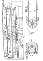
- the car 1 has a doorway with two sliding doors 3a, 3b.
- the tile-shaped support 5 has two end walls 6, the edges 6a of which match the profile of the car.
- the tile-shaped support 5 also carries a central resilient gripper member 34 which engages a catch member 35 carried by the car in the lowered working position of the support 5 shown in Figures 1 and 2.
- An electric motor with two end plates 8 is fixed by screws 9 to the inside of the central part of the tile-shaped support 5.
- the electric motor 7 which may operate, for example, with a variable current of between 12 and 24 volts, rotates two oppositely-threaded worm-screws 12a, 12b respectively, which extend coaxially on opposite sides of the motor 7.
- the outer ends of the screws 12a, 12b are supported by bearings 13 carried by the end walls 6 of the tile-shaped support 5.
- a nut 14 in the form of a parallelepiped block is engaged on each of the screws 12a, 12b, and has a fork-shaped end with two wall portions 15 disposed transverse the common axis of the two screws 12a, 12b.
- each nut has a flat face 15a situated immediately adjacent a corresponding flat zone of the tile-shaped support 5.
- the nuts 14 are prevented from rotating and are therefore displaced axially in opposite directions by the rotation of the rotor of the motor 7.
- the motor 7 is supplied in such a way as to be rotatable in opposite senses, to effect displacement of the two nuts 14 towards the motor 7 in one case, and displacement of the two nuts 14 towards the end walls. 6 of the tile-shaped structure 5 in the other case.
- each fork 15 engages a draw-bolt 16 connected to a support plate 17.
- Each support plate 17 is fixed by a screw 18, with the interpositioning of a rubber plate 19, to a carriage 20 which, with the interpositioning of a sliding device 21, is slidable longitudinally in a guide channel 22.
- Each of the support plates 17 is fixed to a respective sliding door 3a, 3b of the doorway.
- a pair of microswitches 23, 24 are fixed within the tile-shaped support structure 5 and cooperate with one of the nuts 14 to cut off the supply to the motor 7 at the end of the opening and closing strokes, respectively, of the two doors 3a, 3b, which are controlled by the axial displacement of the nuts 14 through the respective draw-bolts 16.
- the microswitches 23, 24 may also supply signals to the effect that the opening or closing of the door has occurred, in order to ensure the correct operation of the system.
- the doors In an emergency (a breakdown of the electric motor 7, an interruption of the current supply to the motor or to rescue passengers in transit) the doors may be opened manually, and extremely simply, by service personnel.
- the entire moving mechanism described above is effectively protected from the weather by the tile-shaped support 5 which has gaskets 10 at the edges 6a and a gasket 11 at the edge which rests on the roof la, thereby preventing the build-up of ice on the moving part of the mechanism itself when it is snowing.
- the suspension arm 25 of the car 1 carries at its upper end a device 26 for automatically clamping onto the cable 27, and a small wheel 28 for supporting the car on the overhead rail of a station.
- Figure 7 shows the path 29 of the car while it is supported by the overhead rail (not shown) between the deceleration zone 30 and the acceleration zone 31.
- each station has three fixed conducting bars 32 which are supported resiliently and connected.
- the bus-bars 32 supply the electric motor 7 through spring contacts 33 carried by the suspension arm 25.
- the polarities of the bus-bars are chosen so as to cause rotation of the motor 7 in the sense corresponding to opening of the doors 3a, 3b in the zone where the passengers alight, and rotation of the motor 7 in the sense corresponding to closing of the doors in the zone where the passengers board.
Landscapes
- Engineering & Computer Science (AREA)
- Transportation (AREA)
- Mechanical Engineering (AREA)
- Power-Operated Mechanisms For Wings (AREA)
Priority Applications (1)
| Application Number | Priority Date | Filing Date | Title |
|---|---|---|---|
| AT81830215T ATE14034T1 (de) | 1981-03-20 | 1981-10-29 | Einrichtung zum bewegen der zwei schiebetueren eines wagens einer seilbahn, mit automatischer blockier- oder fangeinrichtung. |
Applications Claiming Priority (2)
| Application Number | Priority Date | Filing Date | Title |
|---|---|---|---|
| IT6738781 | 1981-03-20 | ||
| IT67387/81A IT1148041B (it) | 1981-03-20 | 1981-03-20 | Dispositivo per la movimentazione della porta a due ante scorrevoli in una cabina di una funivia a moto continuo con ammorsamento od agganciamento automatico telecabina |
Publications (3)
| Publication Number | Publication Date |
|---|---|
| EP0062726A2 true EP0062726A2 (fr) | 1982-10-20 |
| EP0062726A3 EP0062726A3 (en) | 1983-02-23 |
| EP0062726B1 EP0062726B1 (fr) | 1985-06-26 |
Family
ID=11301969
Family Applications (1)
| Application Number | Title | Priority Date | Filing Date |
|---|---|---|---|
| EP81830215A Expired EP0062726B1 (fr) | 1981-03-20 | 1981-10-29 | Dispositif d'actionnement des deux portes coulissantes d'une cabine de téléphérique à blocage ou accrochage automatique |
Country Status (5)
| Country | Link |
|---|---|
| US (1) | US4409905A (fr) |
| EP (1) | EP0062726B1 (fr) |
| AT (1) | ATE14034T1 (fr) |
| DE (2) | DE3171144D1 (fr) |
| IT (1) | IT1148041B (fr) |
Cited By (3)
| Publication number | Priority date | Publication date | Assignee | Title |
|---|---|---|---|---|
| WO1984004283A1 (fr) * | 1983-04-20 | 1984-11-08 | Cwa Const Sa | Caisse pour passagers |
| FR2757205A1 (fr) * | 1996-12-13 | 1998-06-19 | Adronit Verwaltungs Gmbh Co | Porte coulissante pour entrees carrossables |
| EP1632634A2 (fr) * | 2004-09-02 | 2006-03-08 | Vukv A.S. | Une porte actionnée directement par un moteur linéaire destinée au transport public, notamment aux véhicules ferroviaires |
Families Citing this family (8)
| Publication number | Priority date | Publication date | Assignee | Title |
|---|---|---|---|---|
| DE4000555A1 (de) * | 1990-01-10 | 1991-07-11 | Walter Dipl Ing Dr Ing Mehnert | Getriebeanordnung |
| US4977704A (en) * | 1990-04-23 | 1990-12-18 | Koenig Gordon K | Machine shed sliding door operator |
| NL9100951A (nl) * | 1991-06-03 | 1993-01-04 | Tbl Beheer Bv | Zwenkschuifdeurstelsel voor een voertuig. |
| FR2688020B1 (fr) * | 1992-02-28 | 1997-04-11 | Rene Ruchat | Dispositif commandant l'ouverture et la fermeture d'une porte coulissant horizontalement dans un vehicule. |
| DE4446403A1 (de) * | 1994-12-23 | 1996-06-27 | Apprich Secur 2000 Gmbh | Gepanzerte Schiebetür für gegen Einbruch, Beschuß, Aufbruch und unbefugten Zugang zu sichernde Räume |
| US5826377A (en) * | 1996-08-29 | 1998-10-27 | Simson; Anton K. | Remotely-driven power window |
| US9382745B2 (en) * | 2013-12-03 | 2016-07-05 | Andersen Corporation | Powered sash driving apparatus having a connection block |
| EP2889200B1 (fr) * | 2013-12-30 | 2019-07-31 | Vapor Europe S.r.l. A Wabtec Company | Dispositif d'entraînement de porte pour porte de wagon |
Citations (3)
| Publication number | Priority date | Publication date | Assignee | Title |
|---|---|---|---|---|
| DE283831C (fr) * | ||||
| GB421433A (en) * | 1934-03-27 | 1934-12-20 | Fritz Kiekert | Improvements in or relating to opening and closing devices for sliding doors and the like |
| AU446684B2 (en) * | 1971-06-21 | 1974-03-11 | Chubb Australia Limited | A motor actuated door |
Family Cites Families (4)
| Publication number | Priority date | Publication date | Assignee | Title |
|---|---|---|---|---|
| US1215573A (en) * | 1916-12-19 | 1917-02-13 | Arthur H Otis | Door-operating device. |
| GB1104057A (en) * | 1966-04-21 | 1968-02-21 | G D Peters & Co Engineering Lt | Improvements relating to power operated sliding door gear |
| FR2240133B1 (fr) * | 1973-08-07 | 1976-04-30 | Pomagalski Sa | |
| CH611679A5 (en) * | 1976-11-01 | 1979-06-15 | Degiorgi Ag | Device for actuating a door on a cable car or cabin |
-
1981
- 1981-03-20 IT IT67387/81A patent/IT1148041B/it active
- 1981-10-29 DE DE8181830215T patent/DE3171144D1/de not_active Expired
- 1981-10-29 EP EP81830215A patent/EP0062726B1/fr not_active Expired
- 1981-10-29 AT AT81830215T patent/ATE14034T1/de not_active IP Right Cessation
- 1981-10-29 DE DE198181830215T patent/DE62726T1/de active Pending
- 1981-11-27 US US06/325,475 patent/US4409905A/en not_active Expired - Fee Related
Patent Citations (3)
| Publication number | Priority date | Publication date | Assignee | Title |
|---|---|---|---|---|
| DE283831C (fr) * | ||||
| GB421433A (en) * | 1934-03-27 | 1934-12-20 | Fritz Kiekert | Improvements in or relating to opening and closing devices for sliding doors and the like |
| AU446684B2 (en) * | 1971-06-21 | 1974-03-11 | Chubb Australia Limited | A motor actuated door |
Cited By (5)
| Publication number | Priority date | Publication date | Assignee | Title |
|---|---|---|---|---|
| WO1984004283A1 (fr) * | 1983-04-20 | 1984-11-08 | Cwa Const Sa | Caisse pour passagers |
| US4655144A (en) * | 1983-04-20 | 1987-04-07 | Cwa Constructions Sa | Cabin for accommodating passengers |
| FR2757205A1 (fr) * | 1996-12-13 | 1998-06-19 | Adronit Verwaltungs Gmbh Co | Porte coulissante pour entrees carrossables |
| EP1632634A2 (fr) * | 2004-09-02 | 2006-03-08 | Vukv A.S. | Une porte actionnée directement par un moteur linéaire destinée au transport public, notamment aux véhicules ferroviaires |
| EP1632634A3 (fr) * | 2004-09-02 | 2010-02-17 | Vukv A.S. | Une porte actionnée directement par un moteur linéaire destinée au transport public, notamment aux véhicules ferroviaires |
Also Published As
| Publication number | Publication date |
|---|---|
| DE62726T1 (de) | 1983-05-11 |
| EP0062726A3 (en) | 1983-02-23 |
| ATE14034T1 (de) | 1985-07-15 |
| DE3171144D1 (en) | 1985-08-01 |
| IT1148041B (it) | 1986-11-26 |
| US4409905A (en) | 1983-10-18 |
| EP0062726B1 (fr) | 1985-06-26 |
| IT8167387A0 (it) | 1981-03-20 |
Similar Documents
| Publication | Publication Date | Title |
|---|---|---|
| EP0062726B1 (fr) | Dispositif d'actionnement des deux portes coulissantes d'une cabine de téléphérique à blocage ou accrochage automatique | |
| CA2252640C (fr) | Cloison amovible | |
| EP0996802A1 (fr) | Systeme de porte ou de fenetre automatique | |
| EP3581456B1 (fr) | Système de transport par câble | |
| US4712486A (en) | Aerial ropeway transport installation with the rope stopping to detach the cars in the terminal | |
| CA2067594A1 (fr) | Systeme et dispositif de detection d'obstruction pour porte motorisee de vehicule de transport en commun | |
| DE19913996A1 (de) | Antrieb für eine Tür | |
| AU2010206300A1 (en) | Drive system for a door | |
| CA3147486A1 (fr) | Unite de positionnement et procede de mise en contact | |
| CN114069534A (zh) | 一种高压线巡检除冰机器人 | |
| CN109678028A (zh) | 一种同步轮驱动的电梯减震夹轨器 | |
| CN106476648B (zh) | 上下式移动供电系统 | |
| US3115847A (en) | Aerial tramways | |
| DE19902559A1 (de) | Stromzuführung für einen Türflügel | |
| CN112320535A (zh) | 一种电梯用安全轿厢装置 | |
| DE60202141T2 (de) | Automatische transport- und personenführungsanlage und steuerung von transportmodulen in einer solchen anlage | |
| FR2536707B1 (fr) | Dispositif de descente automatique rapide pour pantographe | |
| WO2011078598A2 (fr) | Appareil d'ouverture/fermeture d'une porte coulissante | |
| US4479037A (en) | Trolley bridge | |
| CN211217944U (zh) | 一种用于地铁车站主体结构的除尘装置 | |
| US4020300A (en) | Sectionalized crane collector systems | |
| CN1144927C (zh) | 由多个侧翼组成的滑动间墙系统用的滑轨 | |
| CN217783238U (zh) | 屏蔽门组件 | |
| GB1353155A (en) | Conveyor systems | |
| CN212502497U (zh) | 一种侧挂式轨道小车运输系统及其载物箱 |
Legal Events
| Date | Code | Title | Description |
|---|---|---|---|
| PUAI | Public reference made under article 153(3) epc to a published international application that has entered the european phase |
Free format text: ORIGINAL CODE: 0009012 |
|
| AK | Designated contracting states |
Designated state(s): AT CH DE FR LI |
|
| PUAL | Search report despatched |
Free format text: ORIGINAL CODE: 0009013 |
|
| RAP1 | Party data changed (applicant data changed or rights of an application transferred) |
Owner name: FATA INDUSTRIALE S.P.A. |
|
| AK | Designated contracting states |
Designated state(s): AT CH DE FR LI |
|
| EL | Fr: translation of claims filed | ||
| TCAT | At: translation of patent claims filed | ||
| DET | De: translation of patent claims | ||
| 17P | Request for examination filed |
Effective date: 19830407 |
|
| RAP1 | Party data changed (applicant data changed or rights of an application transferred) |
Owner name: AGUDIO S.P.A. |
|
| GRAA | (expected) grant |
Free format text: ORIGINAL CODE: 0009210 |
|
| AK | Designated contracting states |
Designated state(s): AT CH DE FR LI |
|
| REF | Corresponds to: |
Ref document number: 14034 Country of ref document: AT Date of ref document: 19850715 Kind code of ref document: T |
|
| REF | Corresponds to: |
Ref document number: 3171144 Country of ref document: DE Date of ref document: 19850801 |
|
| ET | Fr: translation filed | ||
| PLBE | No opposition filed within time limit |
Free format text: ORIGINAL CODE: 0009261 |
|
| STAA | Information on the status of an ep patent application or granted ep patent |
Free format text: STATUS: NO OPPOSITION FILED WITHIN TIME LIMIT |
|
| 26N | No opposition filed | ||
| PGFP | Annual fee paid to national office [announced via postgrant information from national office to epo] |
Ref country code: AT Payment date: 19900910 Year of fee payment: 10 |
|
| PGFP | Annual fee paid to national office [announced via postgrant information from national office to epo] |
Ref country code: CH Payment date: 19900925 Year of fee payment: 10 |
|
| PGFP | Annual fee paid to national office [announced via postgrant information from national office to epo] |
Ref country code: DE Payment date: 19900928 Year of fee payment: 10 |
|
| PG25 | Lapsed in a contracting state [announced via postgrant information from national office to epo] |
Ref country code: AT Effective date: 19911029 |
|
| PG25 | Lapsed in a contracting state [announced via postgrant information from national office to epo] |
Ref country code: LI Effective date: 19911031 Ref country code: CH Effective date: 19911031 |
|
| REG | Reference to a national code |
Ref country code: FR Ref legal event code: TP Ref country code: FR Ref legal event code: CD Ref country code: FR Ref legal event code: CA |
|
| REG | Reference to a national code |
Ref country code: CH Ref legal event code: PL |
|
| PG25 | Lapsed in a contracting state [announced via postgrant information from national office to epo] |
Ref country code: DE Effective date: 19920701 |
|
| PGFP | Annual fee paid to national office [announced via postgrant information from national office to epo] |
Ref country code: FR Payment date: 19931029 Year of fee payment: 13 |
|
| PG25 | Lapsed in a contracting state [announced via postgrant information from national office to epo] |
Ref country code: FR Effective date: 19950630 |
|
| REG | Reference to a national code |
Ref country code: FR Ref legal event code: ST |