EP0062484A1 - Verfahren zum Schneiden von Glas mittels eines Lasers - Google Patents
Verfahren zum Schneiden von Glas mittels eines Lasers Download PDFInfo
- Publication number
- EP0062484A1 EP0062484A1 EP82301675A EP82301675A EP0062484A1 EP 0062484 A1 EP0062484 A1 EP 0062484A1 EP 82301675 A EP82301675 A EP 82301675A EP 82301675 A EP82301675 A EP 82301675A EP 0062484 A1 EP0062484 A1 EP 0062484A1
- Authority
- EP
- European Patent Office
- Prior art keywords
- glass
- laser
- focal point
- sheet
- thickness
- Prior art date
- Legal status (The legal status is an assumption and is not a legal conclusion. Google has not performed a legal analysis and makes no representation as to the accuracy of the status listed.)
- Ceased
Links
- 239000011521 glass Substances 0.000 title claims abstract description 214
- 238000005520 cutting process Methods 0.000 title claims abstract description 32
- 238000000034 method Methods 0.000 title claims abstract description 31
- 230000033001 locomotion Effects 0.000 claims abstract description 16
- 238000000137 annealing Methods 0.000 claims abstract description 6
- 239000000463 material Substances 0.000 claims description 13
- 230000008016 vaporization Effects 0.000 claims description 9
- 238000009826 distribution Methods 0.000 claims description 6
- 238000010438 heat treatment Methods 0.000 claims description 6
- 238000004519 manufacturing process Methods 0.000 claims description 6
- 238000005530 etching Methods 0.000 claims description 3
- 239000007789 gas Substances 0.000 description 21
- 230000008859 change Effects 0.000 description 6
- 230000007246 mechanism Effects 0.000 description 6
- 230000008569 process Effects 0.000 description 5
- 239000007787 solid Substances 0.000 description 4
- 230000008901 benefit Effects 0.000 description 3
- 238000005336 cracking Methods 0.000 description 3
- 238000013461 design Methods 0.000 description 3
- 239000007788 liquid Substances 0.000 description 3
- 230000003287 optical effect Effects 0.000 description 3
- 238000009834 vaporization Methods 0.000 description 3
- IJGRMHOSHXDMSA-UHFFFAOYSA-N Atomic nitrogen Chemical compound N#N IJGRMHOSHXDMSA-UHFFFAOYSA-N 0.000 description 2
- CURLTUGMZLYLDI-UHFFFAOYSA-N Carbon dioxide Chemical compound O=C=O CURLTUGMZLYLDI-UHFFFAOYSA-N 0.000 description 2
- VYPSYNLAJGMNEJ-UHFFFAOYSA-N Silicium dioxide Chemical compound O=[Si]=O VYPSYNLAJGMNEJ-UHFFFAOYSA-N 0.000 description 2
- 239000000853 adhesive Substances 0.000 description 2
- 230000001070 adhesive effect Effects 0.000 description 2
- 230000004075 alteration Effects 0.000 description 2
- 229910052782 aluminium Inorganic materials 0.000 description 2
- XAGFODPZIPBFFR-UHFFFAOYSA-N aluminium Chemical compound [Al] XAGFODPZIPBFFR-UHFFFAOYSA-N 0.000 description 2
- 239000000919 ceramic Substances 0.000 description 2
- 239000002178 crystalline material Substances 0.000 description 2
- 238000000354 decomposition reaction Methods 0.000 description 2
- 239000012535 impurity Substances 0.000 description 2
- 238000003754 machining Methods 0.000 description 2
- 229910052751 metal Inorganic materials 0.000 description 2
- 239000002184 metal Substances 0.000 description 2
- 239000000203 mixture Substances 0.000 description 2
- 238000012986 modification Methods 0.000 description 2
- 230000004048 modification Effects 0.000 description 2
- 230000035882 stress Effects 0.000 description 2
- 239000002699 waste material Substances 0.000 description 2
- RYGMFSIKBFXOCR-UHFFFAOYSA-N Copper Chemical compound [Cu] RYGMFSIKBFXOCR-UHFFFAOYSA-N 0.000 description 1
- 239000004593 Epoxy Substances 0.000 description 1
- 230000003190 augmentative effect Effects 0.000 description 1
- 229910002092 carbon dioxide Inorganic materials 0.000 description 1
- 239000001569 carbon dioxide Substances 0.000 description 1
- 239000002131 composite material Substances 0.000 description 1
- 238000011109 contamination Methods 0.000 description 1
- 239000002826 coolant Substances 0.000 description 1
- 238000001816 cooling Methods 0.000 description 1
- 239000011889 copper foil Substances 0.000 description 1
- 238000005553 drilling Methods 0.000 description 1
- 239000000428 dust Substances 0.000 description 1
- 230000000694 effects Effects 0.000 description 1
- 238000005516 engineering process Methods 0.000 description 1
- 238000002474 experimental method Methods 0.000 description 1
- 229910052734 helium Inorganic materials 0.000 description 1
- 239000001307 helium Substances 0.000 description 1
- SWQJXJOGLNCZEY-UHFFFAOYSA-N helium atom Chemical compound [He] SWQJXJOGLNCZEY-UHFFFAOYSA-N 0.000 description 1
- 238000003698 laser cutting Methods 0.000 description 1
- 238000012423 maintenance Methods 0.000 description 1
- 239000011159 matrix material Substances 0.000 description 1
- 239000006060 molten glass Substances 0.000 description 1
- 229910052757 nitrogen Inorganic materials 0.000 description 1
- 230000009467 reduction Effects 0.000 description 1
- 230000008439 repair process Effects 0.000 description 1
- 230000033458 reproduction Effects 0.000 description 1
- 238000007790 scraping Methods 0.000 description 1
- 238000000926 separation method Methods 0.000 description 1
- 238000007493 shaping process Methods 0.000 description 1
- 239000000377 silicon dioxide Substances 0.000 description 1
- 229910000679 solder Inorganic materials 0.000 description 1
- 230000002459 sustained effect Effects 0.000 description 1
- 230000008646 thermal stress Effects 0.000 description 1
- 230000001052 transient effect Effects 0.000 description 1
Images

Classifications
-
- C—CHEMISTRY; METALLURGY
- C03—GLASS; MINERAL OR SLAG WOOL
- C03B—MANUFACTURE, SHAPING, OR SUPPLEMENTARY PROCESSES
- C03B33/00—Severing cooled glass
- C03B33/08—Severing cooled glass by fusing, i.e. by melting through the glass
- C03B33/082—Severing cooled glass by fusing, i.e. by melting through the glass using a focussed radiation beam, e.g. laser
-
- C—CHEMISTRY; METALLURGY
- C03—GLASS; MINERAL OR SLAG WOOL
- C03B—MANUFACTURE, SHAPING, OR SUPPLEMENTARY PROCESSES
- C03B33/00—Severing cooled glass
- C03B33/02—Cutting or splitting sheet glass or ribbons; Apparatus or machines therefor
- C03B33/023—Cutting or splitting sheet glass or ribbons; Apparatus or machines therefor the sheet or ribbon being in a horizontal position
- C03B33/027—Scoring tool holders; Driving mechanisms therefor
-
- C—CHEMISTRY; METALLURGY
- C03—GLASS; MINERAL OR SLAG WOOL
- C03B—MANUFACTURE, SHAPING, OR SUPPLEMENTARY PROCESSES
- C03B33/00—Severing cooled glass
- C03B33/02—Cutting or splitting sheet glass or ribbons; Apparatus or machines therefor
- C03B33/04—Cutting or splitting in curves, especially for making spectacle lenses
Definitions
- This invention relates to the cutting of glass with a laser beam focused upon the glass to be cut, and items made of glass cut with a laser beam.
- One of the more common problems encountered is cutting or shaping the material into pieces having predetermined shapes and sizes, especially shapes with non-linear edges, inside corners, and accurate reproductions of a given shape.
- glass was broken by scribing it on the surface along a line with a diamond-tipped scribe or diamond-tipped saw. This weakened the crystalline structure and, hopefully, the glass would break along the scribe line when an appropriate pressure was exerted to create a force at the scribe line.
- These breaks extended from edge to edge because it is extremely difficult, almost impossible, to control the length of a break or fracture or to terminate it at a predetermined location.
- a still further drawback to the scribing and breaking technique that is of at least equal severity is the limitation to makingS linear edge to edge cuts.
- the positioning accuracy of the scribe line is as good as that of the positioning mechanism, and maintenance of this accuracy is augmented by the almost non-existent tooling forces exerted by a laser.
- the glass is subjected only to the forces of the positioning mechanism for the glass.
- changes or alterations in the cutting pattern may be effected with a simple change in the positioning mechanism, or if the position of the glass or the laser beam is numerically controlled, a change in the controlling program. Such changes may affect the glass position and velocity, laser beam power output, laser beam wave output, width of the scribe line, etc.
- line scribing one may drill a series of closely spaced holes that generally extend vertically downward through the material.
- This process involved vaporization of the entire glass thickness, which refers to decomposition of the glass rather than the usual meaning of phase change from a liquid or solid to a gas.
- the drawbacks of this process include a change of the color of the glass, a change in transparency in a region on each side of the cut, creation of a zone of gas bubbles trapped within the glass on each side of the cut, and an uncut transient section at the beginning of the laser path.
- Still further drawbacks include a high power requirement, not only for operation of the laser to achieve total vaporization, but also for preheating the glass and controlling the rate of cooling after the cut is made.
- the invention includes a method of cutting or etching glass having a predetermined thickness with laser means having a laser beam output, said method comprising positioning the glass in predetermined spaced relationship with respect to the laser means so that a laser beam generated thereby is incident upon said glass, said laser means having a predetermined energy output; focusing said laser beam to a focal point disposed at or about the surface of said glass to locally heat said glass proximate said focal point; vaporizing a first thickness of said glass proximate said laser focal point, said first thickness being less than the total glass thickness; directing a jet of gas so that it is incident upon the proximity of said laser focal point, said jet cooperating with said beam to remove said vaporized glass proximate said laser focal point; and effecting movement between said glass and said laser focal point and gas jet along a predetermined path at a predetermined rate, maintaining said focal point at or about the surface of said glass during any movement, thereby defining said cut or etch.
- the glass does not require any preheating, yet the problem of undesirable crack propagation is eleminated; complicated shapes can be cut; exact and accurate shapes may be repeated in small or large quantities; and an interior portion may be removed from a sheet of glass and replaced with one or more shapes accurately sized to fit that opening.
- a method of cutting glass with a laser beam is disclosed.
- a laser with a predetermined energy output and waveform is provided for directing a laser beam onto glass that is superposed a support means.
- the laser beam is focused to a predetermined configuration and the focal point is disposed at or about the surface of the glass.
- the laser beam When energized, the laser beam, proximate the focal point, vaporizes a portion of the glass thickness and heats the remaining thickness above its annealing temperature.
- a jet of gas is directed at the laser beam focal point and removes the vaporized and heated glass. Movement is effected between the glass and the laser beam and gas jet at predetermined rates, maintaining the laser focal point at or about the surface of the glass, to define a cut through the entire glass thickness.
- the invention also includes articles of manufacture made of a sheet of glass having a cut of predetermined configuration made by a laser.
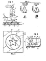
- Fig. 1 illustrates generally the apparatus used to practice the present invention.
- a laser means 1 is optically and mechanically connected to a focusing head 2 by a traverse casing 3.
- the focusing head includes a collar 4 that forms a nozzle or gas jet.
- the focusing head 2 and gas jet assembly is superposed a table 6 having a moveable platen 7.
- the platen has attached thereto a predetermined number of arms 8 that support a sheet of glass 9 above the platen 7.
- the platen, with the attached arms 8 and supported sheet of glass 9 is moved in two dimensions (i.e. within the plane of the glass) so that the laser beam traces a predetermined path, thereby cutting the glass. Further details of the invention and apparatus used are disclosed in subsequent paragraphs herein.
- the laser means 1 includes a housing 5 that encases and suitably supports a laser source 10, including all of the elements to generate a laser beam 11 when the source 10 is suitably energized.
- the direction of beam propagation may be altered and controlled as desired with suitable mirrors 12.
- a control cable 13 connects the laser source to a laser control means 14.
- the laser control means energizes, alters, and otherwise controls the laser beam output of the laser source 10. This control may govern, among other things, the power output of the laser, usually measured in watts, and the waveform or duty cycle of the laser beam by varying it between continuous and intermittent operation.
- a mechanical shutter 15 may be interposed in the path of the laser beam 11 to provide additional beam control and for safety reasons.
- laser source 10 and its control means 14 is not a part of nor necessary for an understanding of the present invention, beyond the information disclosed herein.
- a variety of lasers within the parameters disclosed herein, may be compatible for cutting glass, including but not limited to gas lasers, such as ones having a mixture of carbon dioxide, nitrogen, and helium.
- the laser means 1 is rigidly attached to a solid ground or other base of support 17 at its lower end lA.
- the upper portion 1B is typically attached to a hollow traverse casing 3 that supports the focusing head 2 by suspending it over the sheet of glass 9..
- the configuration of the traverse casing 3 and support 17 may be varied or added to as necessary or desireable, provided that they maintain the focusing head 2 in a predetermined position and isolate it from vibrations or other insults which might result in unwanted movement of the laser beam 11.
- the traverse casing 3 may also support or guide any gas lines.
- the focusing head 2 includes a housing 20 depending from or attached to the traverse casing 3.
- the housing 20 is generally opaque, except for an optional exit window 21, and may be made of metal, plastic, or the like. It is desireable to have the housing 20 sealed shut to eliminate the intrusion of non-transparent impurities, including dust and the like, and for safety reasons, to prevent unwanted emissions of laser energy.
- the exit window preferably has a high efficiency ratio in transferring the laser energy and is of very good optical quality.
- Downstream of the optional exit window 21 is a focusing lens 22 which is also disposed and removably secured within the housing 20. The focusing lens converges the laser beam to a focal point 23.
- the focusing lens 22 should have a high efficiency ratio and be of very good optical quality so that energy losses, beam divergance, and other optical aberrations are minimized.
- this lens may be changed to vary the focal length and beam power to create a focal point having the necessary or desireable energy density.
- Lenses of 5 inches and 3 3/4 inches focal length with a diameter of approximately 1 1/2 inches have been found satisfactory when used with a laser having a power output in excess of approximately 600 to 700 watts.
- This combination results in a laser beam focal point having sufficient energy to vaporize and heat glass in accordance with the present invention.
- Vaporization refers to decomposition of the glass rather than to the traditional phase change from a solid or liquid to a gas.
- a collar 4 may be attached to the housing 20, or may be an integral part thereof, and forms a generally gas tight cavity 26 that is connected to a pressurized supply of gas 27 by a suitable line 27A.
- the collar 4 also defines a nozzle 28 that is generally concentric with the axis of the laser beam and may be an integral part.of the housing.
- the nozzle directs a jet of pressurized gas at the focal point 23 of the laser beam.
- the gas may be atmospheric air or otherwise, provided it is transparent to the laser beam.
- the volume, pressure, and flow rate of the gas may be monitored and controlled by conventional means.
- a sheet of glass 9, shown in a cross-sectional view in Fig. 2 is positioned beneath the laser means 1, with the focused laser beam 11A incident thereon and generally perpendicular thereto.
- the sheet of glass is supported above the platen 7 about one inch or more by a predetermined number of arms 8 and other supports 33.
- An aluminum platen has been found satisfactory because it has high thermal conductivity characteristics and is therefore relatively insensitive to localized heating. This minimizes heat distortion.
- the arms 8 may be of any desired length or dimension, provided they supply adequate support to the sheet of glass.
- Rectangular aluminum bars one by one/half inch have been found satisfactory, and may include a predetermined number of vertically drilled and conveniently spaced holes 34 (not shown in all arms) to aid in securing or positioning the glass sheet 9.
- Auxilliary supports 33 are recommended to insure adequate support along a proposed cutting path and to insure that the sheet of glass remains as nearly flat as possible.
- Upwardly protruding rods with flat or pointed ends or short sections of channel shaped material have been found satisfactory.
- the specific configuration of the supports, the material they are made of, and their position on the platen may be altered as necessary or desireable.
- the moveable platen 7 is attached to a table 6, such as a machining table or the like, and the platen may be moved along X-Y coordinates in a plane parallel to the plane of the sheet of glass 9.
- a table 6 such as a machining table or the like
- the motors are connected to a table control means 40 by suitable control cables 41 and 42 that energize the motors in the proper sequence and at the proper time and rate to effect the desired platen motion.
- the table control means may be digital . or analog and responsive to any variety of inputs well known in the art. This type of table and control mechanism are typical of those used for machining metal. They provide accurate and repeatable motion for both curved and linear motion at preselected rates of movement.
- the preferred embodiment discloses a laser means 1 that is stationary and a sheet of glass that is moved by the controllable table platen 7, this may be reversed as desireable. For instance, with heavier sheets of glass, awkwardly sized sheets, or non-planar glass, it may be desireable to move the focusing head 2 while the glass remains stationary.
- a table or other apparatus that moves in three dimensions, or has a rotational axis like a lathe, may be used to cut irregularly shaped or tubular glass objects.
- the table control means 40 is programmed in a conventional manner to move the sheet of glass in a predetermined direction at a predetermined rate. If the table is numerically or digitally controlled, designs may be digitized, for instance on a digitizer or graphics tablet, such as one manufactured by Talos Systems Inc., Computervision Inc., or the like, and interfaced with the table control 40 in any conventional manner. When so programmed, the table moves the sheeet of glass beneath the focusing head 2.
- The'sheet of glass 9 is placed onto the platen 7, supported by arms 8 and any necessary or desireable other supports 33.
- the supports 33 are generally positioned on opposite sides of the proposed cut at a distance of 1/8 to 1/2 inch from the cut, and the arms 8 preferably extend at least to the edge of the sheet 9.
- the focusing head 2 is positioned above the sheet of glass 9 so that the laser beam is generally vertical with respect to the plane of the sheet.
- the vertical distance above the sheet is adjusted so that the focal point 23 is disposed at or about the surface of the glass.
- the distance from the tip of the air jet nozzle to the glass is generally less than an inch, and usually in the range of one-eighth to one-fourth of an inch. However, this distance may vary according to the type of nozzle used and the desired characteristics of the gas jet.
- the laser means 1 and gas jet 28 are energized.
- most lasers produce a TEMO1 or multi-mode standing wave double peaked beam intensity that focuses to a ring profile.
- This energy distribution is the sum of all of the standing waves created by the laser and is a function of the dimensions of the laser cavity and laser mirrors.
- a multi-mode laser provides a sufficiently dense energy distribution for the present invention to cut glass one-eighth of an inch thick when the laser means 1 is energized to produce a beam 11 having a power output of about 1.2 kilowatts. It has been determined that the energy output may be varied, but energy levels below approximately 600 to 700 watts should be avoided for cutting according to the present invention. These lower power settings result in undesireable cracking, incomplete cutting, and ragged edges.
- the laser beam causes rapid localized heating of the glass in a small vertical heat affected zone 43 (see Fig. 2) that extends through the entire thickness of the glass and is proximate the laser focal point 23.
- a small vertical heat affected zone 43 see Fig. 2
- approximately the top five to thirty percent of the glass adjacent the laser focal point is vaporized.
- the remaining portion of the zone 43 is heated by the focused beam above its annealing range (approximately 950°-1100° F.), at which temperature the glass becomes viscous.
- the space between the glass 9 and the platen 7 allows the air to escape.
- the glass is cut entirely through. Due to the quantum-mechanical nature of the laser beam, only the small cross-section of glass in the heat affected zone 43 is exposed to the high temperature differential, and experiments have demonstrated that the glass, at room temperature, does not crack. Rather, it is cleanly cut with smooth edges, similar to a fire polished edge, producing a kerf of uniform width.
- Figs. 4 and 5 are illustrative.
- a single unitary background sheet of glass 50 was cut to remove an inner circular shape 51, creating a kerf 52.
- a star shape 53 was cut, creating a kerf 54. All three pieces are unbroken and may be lifted out, and the kerfs 52, 54 have smooth edges. Also, none of the cuts extend to the edge of their respective background pieces.
- Pieces of glass may be used individually, or complimentary shaped pieces of glass cut by the same method and by the same or a similar program for the machine table may be inserted into the corresponding openings. For instance, one or more pieces of glass having a composite shape complimentary to one of the openings but having a different color or texture may be placed coplanar to the background piece 50 and secured in edge to edge relation therewith. The edges of the glass are cleaned by scraping, as with the blade of a putty knife, to remove any refused silica, and the glass shapes are reassembled into their desired final configuration. The reassembled pieces of glass may be secured with the traditional copper foil, solder, or lead, or an adhesive, such as one that is a clear, colorless liquid photopolymer consisting of 100% solids.
- Adhesives such as those manufactured by Norland Products, Inc., Epoxy Technology Incorporated, or Tra-Con, Inc. have been found satisfactory. Due to the precision cutting of the laser process, the various interchange pieces fit together precisely to create a kerf of uniform width, facilitating the edge to edge securing of the pieces of glass.
- the uncut unitary background sheet provides structural support for the entire assembly, permitting the assembly to be used as a room divider or the like.
- the interior portions 64, 65 and 66 created by such laser cutting are supported by webs 67.
- the cut is clean, with smooth edges, and no debris attaches on the bottom side of the cut.
- the sheet of glass 59 may be cut to any desired shape.
- one having the benefit of the foregoing may design decorative and functional items of any shape, color or texture of glass.
- the power output should be reduced to approximately 40 watts average power. This reduction in power may be accomplished, for example, by energizing a laser to provide a pulsed output or reduced duty cycle. With a feedrate of approximately 75 inches per minute and an air pressure of approximately 75 p.s.i., a continuous and readily visible etching or scribe line is created that penetrates approximately 2 to 5% into the depth of the glass. There is no damage to or cracking of the underlying glass.
- the same techniques and methods disclosed herein are also suitable for cutting a variety of thicknesses of glass, and it is not limited to the thicknesses disclosed herein.
- the laser energy settings and glass feedrates vary depending upon the type, thickness, color and composition of the glass; the mode output, energy capabilities and power factor of the laser means; the capabilities of the mechanical support table; and the shape of the cut. For instance a sheet of glass 0.128 inches thick may be cut in a circular or contouring shape with a 1.2 kilowatt continuous wave laser beam at speeds from 30 to 100 inches per minute. Speeds for straight cuts are somewhat higher.
- the values provided herein are exemplary only.
Landscapes
- Chemical & Material Sciences (AREA)
- Engineering & Computer Science (AREA)
- Materials Engineering (AREA)
- Organic Chemistry (AREA)
- Physics & Mathematics (AREA)
- Health & Medical Sciences (AREA)
- Optics & Photonics (AREA)
- Toxicology (AREA)
- Re-Forming, After-Treatment, Cutting And Transporting Of Glass Products (AREA)
- Laser Beam Processing (AREA)
- Perforating, Stamping-Out Or Severing By Means Other Than Cutting (AREA)
Applications Claiming Priority (2)
| Application Number | Priority Date | Filing Date | Title |
|---|---|---|---|
| US249854 | 1981-04-01 | ||
| US06/249,854 US4467168A (en) | 1981-04-01 | 1981-04-01 | Method of cutting glass with a laser and an article made therewith |
Publications (1)
| Publication Number | Publication Date |
|---|---|
| EP0062484A1 true EP0062484A1 (de) | 1982-10-13 |
Family
ID=22945290
Family Applications (1)
| Application Number | Title | Priority Date | Filing Date |
|---|---|---|---|
| EP82301675A Ceased EP0062484A1 (de) | 1981-04-01 | 1982-03-30 | Verfahren zum Schneiden von Glas mittels eines Lasers |
Country Status (4)
| Country | Link |
|---|---|
| US (1) | US4467168A (de) |
| EP (1) | EP0062484A1 (de) |
| JP (1) | JPS57209838A (de) |
| CA (1) | CA1188747A (de) |
Cited By (25)
| Publication number | Priority date | Publication date | Assignee | Title |
|---|---|---|---|---|
| FR2543433A1 (fr) * | 1983-03-31 | 1984-10-05 | Cofrec | Procede et dispositif pour tracer une amorce de rupture sur des pointes d'ampoules en verre |
| FR2579974A1 (de) * | 1985-04-03 | 1986-10-10 | Sasaki Glass Kk | |
| DE4214159C1 (de) * | 1992-04-30 | 1993-11-18 | Schott Glaswerke | Verfahren zum Erzeugen von Bruchspannungen in Glas |
| DE19715537A1 (de) * | 1997-04-14 | 1997-10-09 | Schott Glaswerke | Verfahren und Vorrichtung zum Durchtrennen von flachen Werkstücken aus sprödem Material, insbesondere aus Glas |
| DE19616327A1 (de) * | 1996-04-24 | 1997-11-13 | Schott Rohrglas Gmbh | Verfahren und Vorrichtung zum Trennen von dünnwandigen Glasrohren |
| EP0794031A3 (de) * | 1996-03-09 | 1998-01-28 | Arzneimittel GmbH Apotheker Vetter & Co. Ravensburg | Verfahren und Vorrichtung zur Bearbeitung von Werkstücken aus festen Materialien |
| US5984159A (en) * | 1997-04-14 | 1999-11-16 | Schott Glas | Method and apparatus for cutting through a flat workpiece made of brittle material, especially glass |
| US6252197B1 (en) | 1998-12-01 | 2001-06-26 | Accudyne Display And Semiconductor Systems, Inc. | Method and apparatus for separating non-metallic substrates utilizing a supplemental mechanical force applicator |
| EP1112974A2 (de) * | 1999-12-30 | 2001-07-04 | Schott Desag AG | Verfahren zum Herstellen vorgespannter oder gebogener Gläser |
| US6259058B1 (en) | 1998-12-01 | 2001-07-10 | Accudyne Display And Semiconductor Systems, Inc. | Apparatus for separating non-metallic substrates |
| WO2001074726A1 (de) * | 2000-04-04 | 2001-10-11 | Schott Glas | Verfahren zum herstellen von kleinen dünnglasscheiben und grössere dünnglasscheibe als halbfabrikat für dieses herstellen |
| WO2001098015A2 (de) * | 2000-06-21 | 2001-12-27 | Schott Glas | Verfahren zur herstellung von glassubstraten für elektronische speichermedien |
| WO2002008131A1 (de) * | 2000-07-25 | 2002-01-31 | Optische Werke G. Rodenstock | Verfahren zur herstellung eines brillenglases |
| DE10065688A1 (de) * | 2000-12-29 | 2002-07-11 | Schott Glas | Verfahren und Vorrichtung zum Schneiden eines Werkstückes aus sprödbrüchigem Werkstoff |
| US6420678B1 (en) | 1998-12-01 | 2002-07-16 | Brian L. Hoekstra | Method for separating non-metallic substrates |
| US6489588B1 (en) | 1999-11-24 | 2002-12-03 | Applied Photonics, Inc. | Method and apparatus for separating non-metallic materials |
| DE19856347C2 (de) * | 1998-12-07 | 2002-12-19 | Schott Spezialglas Gmbh | Verfahren und Vorrichtung zum Schneiden eines dünnen Werkstücks aus sprödbrüchigem Werkstoff |
| DE10164579C1 (de) * | 2001-12-28 | 2003-08-21 | Jenoptik Automatisierungstech | Verfahren zum Trennen von Lichtleitfasern mittels CO¶2¶-Laserstrahlung |
| WO2004083133A2 (en) * | 2003-03-21 | 2004-09-30 | Rorze Systems Corporation | Apparatus for cutting glass plate |
| DE102005024497A1 (de) * | 2005-05-27 | 2006-11-30 | Schott Ag | Verfahren zum mechanischen Brechen von geritzten flachen Werkstücken aus sprödbrüchigem Material |
| CN1325406C (zh) * | 2003-03-21 | 2007-07-11 | 罗兹系统公司 | 用于切割玻璃板的装置 |
| DE102006029073B4 (de) * | 2005-07-06 | 2009-07-16 | Schott Ag | Verfahren zum Durchtrennen eines Flachglases unter Verwendung eines Lasertrennstrahls und alkalifreies Flachglas mit besonderer Eignung hierfür |
| WO2014059108A1 (en) * | 2012-10-12 | 2014-04-17 | Go!Foton Holdings, Inc. | Method of manufacture of a concave lens assembly, and a concave lense assembly |
| CN104692638A (zh) * | 2015-02-02 | 2015-06-10 | 北京工业大学 | 一种激光切割玻璃的方法 |
| US10631733B2 (en) | 2017-03-13 | 2020-04-28 | Go!Foton Holdings, Inc. | Lens combination for an optical probe and assembly thereof |
Families Citing this family (103)
| Publication number | Priority date | Publication date | Assignee | Title |
|---|---|---|---|---|
| US4530061A (en) * | 1982-10-15 | 1985-07-16 | Wood-Tics Inc. | Method of producing stencils |
| JPS61189890A (ja) * | 1985-02-18 | 1986-08-23 | Matsushita Electric Ind Co Ltd | レ−ザ加工装置 |
| US4678422A (en) * | 1985-11-12 | 1987-07-07 | York Kenneth K | Systems and methods for precise, accurate formation of products by photoablation |
| US4636608A (en) * | 1985-11-15 | 1987-01-13 | Benteler Corporation | Laser contour cut door beams |
| US4644128A (en) * | 1986-01-21 | 1987-02-17 | Benteler Corporation | Laser contour cut manifolds |
| US4865919A (en) * | 1987-01-02 | 1989-09-12 | Ppg Industries, Inc. | Method of fabricating a curved glass panel having a removable section and glass panel with a removable section |
| NZ224424A (en) * | 1987-11-06 | 1990-12-21 | Ian Robert Edmonds | Light deflecting window panel: parallel cuts in transparent material by laser |
| US5352495A (en) * | 1989-02-16 | 1994-10-04 | The Wiggins Teape Group Limited | Treatment of a surface by laser energy |
| EP0397236B1 (de) * | 1989-05-08 | 1994-10-05 | Koninklijke Philips Electronics N.V. | Verfahren zum Spalten einer Platte aus sprödem Werkstoff |
| JPH03216287A (ja) * | 1990-01-19 | 1991-09-24 | Fanuc Ltd | レーザ切断加工方法 |
| JPH04182090A (ja) * | 1990-11-19 | 1992-06-29 | Koike Sanso Kogyo Co Ltd | レーザー加工装置 |
| RU2024441C1 (ru) * | 1992-04-02 | 1994-12-15 | Владимир Степанович Кондратенко | Способ резки неметаллических материалов |
| US5369553A (en) * | 1992-04-24 | 1994-11-29 | Trusiani; Paul J. | Illuminated panel device and method of manufacture |
| US5636914A (en) * | 1992-04-24 | 1997-06-10 | Trusiani; Paul J. | Illuminated panel device |
| JP2658809B2 (ja) * | 1992-08-27 | 1997-09-30 | 三菱電機株式会社 | レーザ加工装置 |
| US5653627A (en) * | 1992-08-28 | 1997-08-05 | Central Glass Company Limited | Flat diamond drill |
| DE4411037C2 (de) * | 1993-04-02 | 1995-07-20 | Fraunhofer Ges Forschung | Verfahren zum Schneiden von Hohlglas |
| US5387776A (en) * | 1993-05-11 | 1995-02-07 | General Electric Company | Method of separation of pieces from super hard material by partial laser cut and pressure cleavage |
| US5504301A (en) * | 1994-03-21 | 1996-04-02 | Laser Cut Images International, Inc. | Apparatus and method for laser engraving thin sheet-like materials |
| US5581971A (en) * | 1994-09-16 | 1996-12-10 | Alumet Manufacturing, Inc. | Glass spacer bar for use in multipane window construction and method of making the same |
| US5776220A (en) * | 1994-09-19 | 1998-07-07 | Corning Incorporated | Method and apparatus for breaking brittle materials |
| US5871134A (en) * | 1994-12-27 | 1999-02-16 | Asahi Glass Company Ltd. | Method and apparatus for breaking and cutting a glass ribbon |
| KR970008386A (ko) * | 1995-07-07 | 1997-02-24 | 하라 세이지 | 기판의 할단(割斷)방법 및 그 할단장치 |
| KR100447786B1 (ko) * | 1995-08-31 | 2004-11-06 | 코닝 인코포레이티드 | 취성물질절단방법및그장치 |
| US6163010A (en) * | 1996-10-25 | 2000-12-19 | E. I. Du Pont De Nemours And Company | Method and apparatus for laser cutting materials |
| IT1284082B1 (it) * | 1996-06-27 | 1998-05-08 | Calp Spa | Metodo e dispositivo per il taglio mediante un raggio laser di articoli cavi in vetro |
| US5816897A (en) * | 1996-09-16 | 1998-10-06 | Corning Incorporated | Method and apparatus for edge finishing glass |
| DE19735356A1 (de) * | 1997-08-14 | 1999-02-18 | Linde Ag | Verfahren zum Laserschneiden von Glas |
| DE19735357A1 (de) * | 1997-08-14 | 1999-02-18 | Linde Ag | Verfahren zum Laserschneiden von Glas |
| US6211488B1 (en) | 1998-12-01 | 2001-04-03 | Accudyne Display And Semiconductor Systems, Inc. | Method and apparatus for separating non-metallic substrates utilizing a laser initiated scribe |
| KR100300416B1 (ko) * | 1999-01-18 | 2001-09-22 | 김순택 | 비금속 재료의 절단방법 및 그 장치 |
| DE19904978A1 (de) * | 1999-02-06 | 2000-08-10 | Vetter & Co Apotheker | Verfahren zur Herstellung von Zylinderrohrabschnitten aus vorzugsweise aus Glas bestehenden Rohren und Vorrichtung zur Durchführung des Verfahrens |
| US6325704B1 (en) * | 1999-06-14 | 2001-12-04 | Corning Incorporated | Method for finishing edges of glass sheets |
| KR100606955B1 (ko) * | 1999-09-21 | 2006-07-31 | 엘지.필립스 엘시디 주식회사 | 레이저 절단장치 및 그것에 의한 유리기판 절단방법 |
| DE19952331C1 (de) * | 1999-10-29 | 2001-08-30 | Schott Spezialglas Gmbh | Verfahren und Vorrichtung zum schnellen Schneiden eines Werkstücks aus sprödbrüchigem Werkstoff mittels Laserstrahlen |
| DE10000469C2 (de) * | 2000-01-07 | 2003-07-03 | Schott Spezialglas Gmbh | Verfahren zum fortlaufenden Ablängen von Zuschnitten aus einem kontinuierlich bewegten Endlosmaterial und zugehörige Vorrichtung |
| US6829910B1 (en) * | 2000-04-25 | 2004-12-14 | Asahi Glass Company, Ltd. | Removal of enclosed glass parts after cutting using heating and cooling techniques |
| CA2314763A1 (en) * | 2000-07-28 | 2002-01-28 | John Ross Campbell | Laminated glass panels |
| DE10047850A1 (de) * | 2000-09-27 | 2002-04-25 | Schott Rohrglas Gmbh | Verfahren und Vorrichtung zum Ablängen von Glasrohren |
| US20020170318A1 (en) * | 2001-04-02 | 2002-11-21 | Andreas Gartner | Brief summary of the invention |
| KR100701013B1 (ko) * | 2001-05-21 | 2007-03-29 | 삼성전자주식회사 | 레이저 빔을 이용한 비금속 기판의 절단방법 및 장치 |
| US6844537B2 (en) | 2001-12-31 | 2005-01-18 | Honeywell International Inc. | Method and device for measuring the velocity of a moving surface |
| US20030155328A1 (en) * | 2002-02-15 | 2003-08-21 | Huth Mark C. | Laser micromachining and methods and systems of same |
| WO2003076150A1 (fr) * | 2002-03-12 | 2003-09-18 | Mitsuboshi Diamond Industrial Co., Ltd. | Procede et systeme d'usinage d'un materiau fragile |
| US6919531B2 (en) * | 2002-03-25 | 2005-07-19 | Agilent Technologies, Inc. | Methods for producing glass substrates for use in biopolymeric microarrays |
| US20050155956A1 (en) * | 2002-08-30 | 2005-07-21 | Sumitomo Heavy Industries, Ltd. | Laser processing method and processing device |
| US6969822B2 (en) * | 2003-05-13 | 2005-11-29 | Hewlett-Packard Development Company, L.P. | Laser micromachining systems |
| US7754999B2 (en) | 2003-05-13 | 2010-07-13 | Hewlett-Packard Development Company, L.P. | Laser micromachining and methods of same |
| GB0328370D0 (en) * | 2003-12-05 | 2004-01-14 | Southampton Photonics Ltd | Apparatus for providing optical radiation |
| US20060021977A1 (en) * | 2004-07-30 | 2006-02-02 | Menegus Harry E | Process and apparatus for scoring a brittle material incorporating moving optical assembly |
| US7820941B2 (en) * | 2004-07-30 | 2010-10-26 | Corning Incorporated | Process and apparatus for scoring a brittle material |
| US20090078370A1 (en) * | 2004-08-31 | 2009-03-26 | Vladislav Sklyarevich | Method of separating non-metallic material using microwave radiation |
| FR2885071B1 (fr) * | 2005-04-28 | 2010-02-12 | Becton Dickinson France | Procede d'identification d'un contenant et/ou d'un article fini obtenu a partir dudit contenant, en particulier a usage medical |
| US20080236199A1 (en) * | 2005-07-28 | 2008-10-02 | Vladislav Sklyarevich | Method of Separating Non-Metallic Material Using Microwave Radiation |
| US20080047940A1 (en) * | 2006-08-28 | 2008-02-28 | Xinghua Li | Article with multiple surface depressions and method for making the same |
| WO2008033948A2 (en) * | 2006-09-12 | 2008-03-20 | Pittsburgh Corning Corporation | Architectural glass block with a formed slot and method of making same |
| US20080206509A1 (en) * | 2006-11-02 | 2008-08-28 | Richard Kent | Inlaid Decorative Panels |
| KR101303542B1 (ko) * | 2008-02-11 | 2013-09-03 | 엘지디스플레이 주식회사 | 평판표시패널 절단장치 |
| US8051679B2 (en) * | 2008-09-29 | 2011-11-08 | Corning Incorporated | Laser separation of glass sheets |
| US8895892B2 (en) * | 2008-10-23 | 2014-11-25 | Corning Incorporated | Non-contact glass shearing device and method for scribing or cutting a moving glass sheet |
| TWI490176B (zh) * | 2009-03-20 | 2015-07-01 | Corning Inc | 分離玻璃板材的製程與設備 |
| US8132427B2 (en) * | 2009-05-15 | 2012-03-13 | Corning Incorporated | Preventing gas from occupying a spray nozzle used in a process of scoring a hot glass sheet |
| US8857128B2 (en) * | 2009-05-18 | 2014-10-14 | Apple Inc. | Reinforced device housing |
| JP5609870B2 (ja) * | 2009-07-03 | 2014-10-22 | 旭硝子株式会社 | 脆性材料基板の割断方法及び割断装置並びにその割断方法により得られる車両用窓ガラス |
| US8932510B2 (en) | 2009-08-28 | 2015-01-13 | Corning Incorporated | Methods for laser cutting glass substrates |
| US8946590B2 (en) * | 2009-11-30 | 2015-02-03 | Corning Incorporated | Methods for laser scribing and separating glass substrates |
| KR101097327B1 (ko) * | 2010-01-07 | 2011-12-23 | 삼성모바일디스플레이주식회사 | 기판 밀봉에 사용되는 레이저 빔 조사 장치 및 이를 이용한 유기 발광 디스플레이 장치의 제조 방법 |
| US8408972B2 (en) * | 2010-01-25 | 2013-04-02 | Apple Inc. | Apparatus and method for intricate cuts |
| DE102010012265B4 (de) * | 2010-03-22 | 2012-09-06 | Fraunhofer-Gesellschaft zur Förderung der angewandten Forschung e.V. | Verfahren zum Heraustrennen von Einzelscheiben aus einer Verbundglastafel und Verwendung einer Vorrichtung dafür |
| US8372495B2 (en) | 2010-05-26 | 2013-02-12 | Apple Inc. | Electronic device enclosure using sandwich construction |
| US9120272B2 (en) | 2010-07-22 | 2015-09-01 | Apple Inc. | Smooth composite structure |
| US8720228B2 (en) * | 2010-08-31 | 2014-05-13 | Corning Incorporated | Methods of separating strengthened glass substrates |
| US9011623B2 (en) | 2011-03-03 | 2015-04-21 | Apple Inc. | Composite enclosure |
| CN104691058B (zh) * | 2011-05-13 | 2016-09-28 | 日本电气硝子株式会社 | 层叠体、层叠体的切断方法和层叠体的加工方法、以及脆性板状物的切断装置和切断方法 |
| US8721392B2 (en) | 2011-06-28 | 2014-05-13 | Corning Incorporated | Glass edge finishing method |
| EP2990389B1 (de) * | 2011-09-15 | 2019-02-27 | Nippon Electric Glass Co., Ltd | Verfahren zum schneiden von glasscheiben |
| CN103212856B (zh) * | 2012-01-19 | 2016-02-24 | 昆山思拓机器有限公司 | 一种用紫外激光加工较厚材料的工艺方法 |
| US9938180B2 (en) | 2012-06-05 | 2018-04-10 | Corning Incorporated | Methods of cutting glass using a laser |
| CN102749746B (zh) * | 2012-06-21 | 2015-02-18 | 深圳市华星光电技术有限公司 | 液晶基板切割装置及液晶基板切割方法 |
| KR20150035577A (ko) * | 2012-06-28 | 2015-04-06 | 아사히 가라스 가부시키가이샤 | 유리 기판의 절단 방법 및 유리 기판의 제조 방법 |
| US9120179B2 (en) * | 2012-09-20 | 2015-09-01 | Apple Inc. | Multi-step cutting process |
| US9610653B2 (en) | 2012-09-21 | 2017-04-04 | Electro Scientific Industries, Inc. | Method and apparatus for separation of workpieces and articles produced thereby |
| WO2014077117A1 (ja) * | 2012-11-13 | 2014-05-22 | 日本電気硝子株式会社 | 板ガラスの製造方法、及び製造装置 |
| JP6378696B2 (ja) | 2013-01-30 | 2018-08-22 | コーニング インコーポレイテッド | フレキシブルガラスの連続レーザ切断装置および方法 |
| US9919380B2 (en) * | 2013-02-23 | 2018-03-20 | Coherent, Inc. | Shaping of brittle materials with controlled surface and bulk properties |
| US10407955B2 (en) | 2013-03-13 | 2019-09-10 | Apple Inc. | Stiff fabric |
| US9360284B1 (en) * | 2013-03-15 | 2016-06-07 | Vista Outdoor Operations Llc | Manufacturing process to produce metalurgically programmed terminal performance projectiles |
| WO2014192482A1 (ja) * | 2013-05-28 | 2014-12-04 | 旭硝子株式会社 | ガラス基板の切断方法及びガラス基板の製造方法 |
| TWI626345B (zh) | 2013-12-20 | 2018-06-11 | 蘋果公司 | 編織物條帶、產生用於一編織物條帶之一固定機構的方法及用於產生用於固定至一物件之一編織物條帶的方法 |
| US9260337B2 (en) | 2014-01-09 | 2016-02-16 | Corning Incorporated | Methods and apparatus for free-shape cutting of flexible thin glass |
| US9844833B2 (en) | 2014-01-30 | 2017-12-19 | Apple Inc. | System and method for laser cutting sapphire using multiple gas media |
| JP6262039B2 (ja) * | 2014-03-17 | 2018-01-17 | 株式会社ディスコ | 板状物の加工方法 |
| JP6301203B2 (ja) | 2014-06-02 | 2018-03-28 | 株式会社ディスコ | チップの製造方法 |
| US10639746B1 (en) | 2014-06-20 | 2020-05-05 | Apple Inc. | Ceramic-based components having laser-etched markings |
| CN104310779A (zh) * | 2014-09-29 | 2015-01-28 | 合肥鑫晟光电科技有限公司 | 一种激光切割基板的方法及激光切割设备 |
| US10576651B2 (en) * | 2015-02-03 | 2020-03-03 | Central Glass Co., Ltd. | Method of cutting brittle material, device for cutting brittle material, method of manufacturing cut brittle material and cut brittle material |
| DE102015111490A1 (de) * | 2015-07-15 | 2017-01-19 | Schott Ag | Verfahren und Vorrichtung zum lasergestützten Abtrennen eines Teilstücks von einem flächigen Glaselement |
| US10144107B2 (en) | 2015-09-30 | 2018-12-04 | Apple Inc. | Ultrasonic polishing systems and methods of polishing brittle components for electronic devices |
| US10864686B2 (en) | 2017-09-25 | 2020-12-15 | Apple Inc. | Continuous carbon fiber winding for thin structural ribs |
| US11454480B1 (en) | 2019-06-12 | 2022-09-27 | Corvid Technologies LLC | Methods for forming munitions casings and casings and munitions formed thereby |
| CN112783264A (zh) | 2019-11-11 | 2021-05-11 | 苹果公司 | 包括纹理化陶瓷盖的生物识别按键 |
| US11113494B2 (en) | 2019-11-11 | 2021-09-07 | Apple Inc. | Biometric key including a textured ceramic cover |
| CN114804609A (zh) * | 2022-04-14 | 2022-07-29 | 济南金威刻科技发展有限公司 | 应用于厚玻璃纵向多焦点激光隐形加工装置 |
Citations (4)
| Publication number | Priority date | Publication date | Assignee | Title |
|---|---|---|---|---|
| US3453097A (en) * | 1964-10-19 | 1969-07-01 | Gerhard Mensel Glasbearbeitung | Method of working glass with absorbent by a laser beam |
| US3597578A (en) * | 1967-03-16 | 1971-08-03 | Nat Res Dev | Thermal cutting apparatus and method |
| GB1367767A (en) * | 1970-12-31 | 1974-09-25 | Secr Defence | Laser machining of oxide materials |
| GB1433563A (en) * | 1973-05-04 | 1976-04-28 | Commissariat Energie Atomique | Method of and apparatus for cutting glass |
Family Cites Families (1)
| Publication number | Priority date | Publication date | Assignee | Title |
|---|---|---|---|---|
| US3930825A (en) * | 1974-11-29 | 1976-01-06 | Ford Motor Company | Method of laser beam cutting of a ribbon of hot glass |
-
1981
- 1981-04-01 US US06/249,854 patent/US4467168A/en not_active Expired - Fee Related
-
1982
- 1982-03-30 EP EP82301675A patent/EP0062484A1/de not_active Ceased
- 1982-03-31 CA CA000400032A patent/CA1188747A/en not_active Expired
- 1982-04-01 JP JP57052375A patent/JPS57209838A/ja active Pending
Patent Citations (5)
| Publication number | Priority date | Publication date | Assignee | Title |
|---|---|---|---|---|
| US3453097A (en) * | 1964-10-19 | 1969-07-01 | Gerhard Mensel Glasbearbeitung | Method of working glass with absorbent by a laser beam |
| US3597578A (en) * | 1967-03-16 | 1971-08-03 | Nat Res Dev | Thermal cutting apparatus and method |
| US3749878A (en) * | 1967-03-16 | 1973-07-31 | Nat Res Dev | Gas assisted laser cutting apparatus |
| GB1367767A (en) * | 1970-12-31 | 1974-09-25 | Secr Defence | Laser machining of oxide materials |
| GB1433563A (en) * | 1973-05-04 | 1976-04-28 | Commissariat Energie Atomique | Method of and apparatus for cutting glass |
Non-Patent Citations (1)
| Title |
|---|
| AMERICAN REVIEW: "Glass and Ceramics", no. 29, 1972, pages 642-644; * |
Cited By (39)
| Publication number | Priority date | Publication date | Assignee | Title |
|---|---|---|---|---|
| FR2543433A1 (fr) * | 1983-03-31 | 1984-10-05 | Cofrec | Procede et dispositif pour tracer une amorce de rupture sur des pointes d'ampoules en verre |
| FR2579974A1 (de) * | 1985-04-03 | 1986-10-10 | Sasaki Glass Kk | |
| DE4214159C1 (de) * | 1992-04-30 | 1993-11-18 | Schott Glaswerke | Verfahren zum Erzeugen von Bruchspannungen in Glas |
| EP0794031A3 (de) * | 1996-03-09 | 1998-01-28 | Arzneimittel GmbH Apotheker Vetter & Co. Ravensburg | Verfahren und Vorrichtung zur Bearbeitung von Werkstücken aus festen Materialien |
| DE19616327A1 (de) * | 1996-04-24 | 1997-11-13 | Schott Rohrglas Gmbh | Verfahren und Vorrichtung zum Trennen von dünnwandigen Glasrohren |
| DE19616327C2 (de) * | 1996-04-24 | 1999-07-22 | Schott Rohrglas Gmbh | Verfahren und Vorrichtung zum Trennen von dünnwandigen Glasrohren |
| DE19715537A1 (de) * | 1997-04-14 | 1997-10-09 | Schott Glaswerke | Verfahren und Vorrichtung zum Durchtrennen von flachen Werkstücken aus sprödem Material, insbesondere aus Glas |
| DE19715537C2 (de) * | 1997-04-14 | 1999-08-05 | Schott Glas | Verfahren und Vorrichtung zum Durchtrennen von flachen Werkstücken aus sprödem Material, insbesondere aus Glas |
| US5984159A (en) * | 1997-04-14 | 1999-11-16 | Schott Glas | Method and apparatus for cutting through a flat workpiece made of brittle material, especially glass |
| US6420678B1 (en) | 1998-12-01 | 2002-07-16 | Brian L. Hoekstra | Method for separating non-metallic substrates |
| US6252197B1 (en) | 1998-12-01 | 2001-06-26 | Accudyne Display And Semiconductor Systems, Inc. | Method and apparatus for separating non-metallic substrates utilizing a supplemental mechanical force applicator |
| US6259058B1 (en) | 1998-12-01 | 2001-07-10 | Accudyne Display And Semiconductor Systems, Inc. | Apparatus for separating non-metallic substrates |
| DE19856347C2 (de) * | 1998-12-07 | 2002-12-19 | Schott Spezialglas Gmbh | Verfahren und Vorrichtung zum Schneiden eines dünnen Werkstücks aus sprödbrüchigem Werkstoff |
| US6660963B2 (en) | 1999-11-24 | 2003-12-09 | Applied Photonics, Inc. | Method and apparatus for separating non-metallic materials |
| US6489588B1 (en) | 1999-11-24 | 2002-12-03 | Applied Photonics, Inc. | Method and apparatus for separating non-metallic materials |
| EP1112974A3 (de) * | 1999-12-30 | 2001-11-28 | Schott Desag AG | Verfahren zum Herstellen vorgespannter oder gebogener Gläser |
| EP1112974A2 (de) * | 1999-12-30 | 2001-07-04 | Schott Desag AG | Verfahren zum Herstellen vorgespannter oder gebogener Gläser |
| WO2001074726A1 (de) * | 2000-04-04 | 2001-10-11 | Schott Glas | Verfahren zum herstellen von kleinen dünnglasscheiben und grössere dünnglasscheibe als halbfabrikat für dieses herstellen |
| US7371431B2 (en) | 2000-04-04 | 2008-05-13 | Schott Ag | Method for producing small, sheet glass plates and larger sheet glass plates as semifinished products for producing the former |
| WO2001098015A2 (de) * | 2000-06-21 | 2001-12-27 | Schott Glas | Verfahren zur herstellung von glassubstraten für elektronische speichermedien |
| WO2001098015A3 (de) * | 2000-06-21 | 2002-04-18 | Schott Glas | Verfahren zur herstellung von glassubstraten für elektronische speichermedien |
| WO2002008131A1 (de) * | 2000-07-25 | 2002-01-31 | Optische Werke G. Rodenstock | Verfahren zur herstellung eines brillenglases |
| US6857743B2 (en) | 2000-07-25 | 2005-02-22 | Rodenstock Gmbh | Method of manufacturing a spectacle lens |
| DE10065688A1 (de) * | 2000-12-29 | 2002-07-11 | Schott Glas | Verfahren und Vorrichtung zum Schneiden eines Werkstückes aus sprödbrüchigem Werkstoff |
| DE10065688B4 (de) * | 2000-12-29 | 2004-05-06 | Schott Glas | Verfahren und Vorrichtung zum Schneiden eines Werkstückes aus sprödbrüchigem Werkstoff |
| DE10164579C1 (de) * | 2001-12-28 | 2003-08-21 | Jenoptik Automatisierungstech | Verfahren zum Trennen von Lichtleitfasern mittels CO¶2¶-Laserstrahlung |
| WO2004083133A2 (en) * | 2003-03-21 | 2004-09-30 | Rorze Systems Corporation | Apparatus for cutting glass plate |
| CN1325406C (zh) * | 2003-03-21 | 2007-07-11 | 罗兹系统公司 | 用于切割玻璃板的装置 |
| WO2004083133A3 (en) * | 2003-03-21 | 2004-12-16 | Rorze Systems Corp | Apparatus for cutting glass plate |
| US7638730B2 (en) | 2003-03-21 | 2009-12-29 | Rorze Systems Corporation | Apparatus for cutting glass plate |
| DE102005024497A1 (de) * | 2005-05-27 | 2006-11-30 | Schott Ag | Verfahren zum mechanischen Brechen von geritzten flachen Werkstücken aus sprödbrüchigem Material |
| DE102005024497B4 (de) * | 2005-05-27 | 2008-06-19 | Schott Ag | Verfahren zum mechanischen Brechen von geritzten flachen Werkstücken aus sprödbrüchigem Material |
| US7628303B2 (en) | 2005-05-27 | 2009-12-08 | Schott Ag | Method of mechanically breaking a scribed workpiece of brittle fracturing material |
| DE102006029073B4 (de) * | 2005-07-06 | 2009-07-16 | Schott Ag | Verfahren zum Durchtrennen eines Flachglases unter Verwendung eines Lasertrennstrahls und alkalifreies Flachglas mit besonderer Eignung hierfür |
| WO2014059108A1 (en) * | 2012-10-12 | 2014-04-17 | Go!Foton Holdings, Inc. | Method of manufacture of a concave lens assembly, and a concave lense assembly |
| US9069122B2 (en) | 2012-10-12 | 2015-06-30 | Go!Foton Holdings, Inc. | Concave lens assembly |
| CN104692638A (zh) * | 2015-02-02 | 2015-06-10 | 北京工业大学 | 一种激光切割玻璃的方法 |
| US10631733B2 (en) | 2017-03-13 | 2020-04-28 | Go!Foton Holdings, Inc. | Lens combination for an optical probe and assembly thereof |
| US11432725B2 (en) | 2017-03-13 | 2022-09-06 | Go!Foton Holdings, Inc. | Optical probe and assembly thereof having specific optical component adhesive configuration |
Also Published As
| Publication number | Publication date |
|---|---|
| CA1188747A (en) | 1985-06-11 |
| US4467168A (en) | 1984-08-21 |
| JPS57209838A (en) | 1982-12-23 |
Similar Documents
| Publication | Publication Date | Title |
|---|---|---|
| US4467168A (en) | Method of cutting glass with a laser and an article made therewith | |
| US6870129B2 (en) | Method and device for cutting a flat glass plate into a number of rectangular plates | |
| US6800831B1 (en) | Method and device for rapid cutting of a workpiece from a brittle material | |
| CN109926584B (zh) | 一种增材制造和表面抛光同步加工方法及装置 | |
| US6787732B1 (en) | Method for laser-scribing brittle substrates and apparatus therefor | |
| EP3363771B1 (de) | Verfahren zum bearbeiten und entlösen von geschlossenen formen aus einem transparenten material unter verwendung von gruppen von ultrakurzlaserpulsen | |
| JP6416901B2 (ja) | 平坦なワークピースを複数の部分に分割する方法及び装置 | |
| US6811069B2 (en) | Method and device for the separation of flat workpieces made from a brittle material | |
| TWI460044B (zh) | Thermal Stress Cutting Method for Brittle Materials | |
| US6259058B1 (en) | Apparatus for separating non-metallic substrates | |
| JP5432285B2 (ja) | 面取りした端部を有する形状にガラスをレーザ加工する方法 | |
| KR20060043352A (ko) | 취성 재료로 이루어진 곡선형 기판을 자유로운 형태로 절단하는 방법 | |
| CN104972226A (zh) | 一种双头激光加工装置及加工方法 | |
| KR101200789B1 (ko) | 취성 재료 기판의 할단 방법 | |
| KR20110006678A (ko) | 취성 재료 기판의 가공 방법 | |
| KR20160093593A (ko) | 거친 표면을 가진 기판을 내부적으로 마킹하는 방법 및 장치 | |
| JP2005212364A (ja) | 脆性材料の割断加工システム及びその方法 | |
| Hermanns | Laser cutting of glass | |
| US6635848B2 (en) | Method and device for cutting flat work pieces of a brittle material | |
| JP2007301672A (ja) | 透明材料の加工方法及び加工装置 | |
| RU209801U1 (ru) | Устройство лазерной резки образца из хрупкого неметаллического материала | |
| Toenshoff et al. | High-quality laser cutting of ceramics through adapted process techniques | |
| Tönshoff et al. | Ceramics processing with laser radiation | |
| RU211415U1 (ru) | Устройство лазерной резки образца из хрупкого неметаллического материала | |
| Harry et al. | Electrothermal cutting processes using a CO 2 laser |
Legal Events
| Date | Code | Title | Description |
|---|---|---|---|
| PUAI | Public reference made under article 153(3) epc to a published international application that has entered the european phase |
Free format text: ORIGINAL CODE: 0009012 |
|
| AK | Designated contracting states |
Designated state(s): AT BE CH DE FR GB IT LU NL SE |
|
| 17P | Request for examination filed |
Effective date: 19830411 |
|
| STAA | Information on the status of an ep patent application or granted ep patent |
Free format text: STATUS: THE APPLICATION HAS BEEN REFUSED |
|
| 18R | Application refused |
Effective date: 19860420 |
|
| RIN1 | Information on inventor provided before grant (corrected) |
Inventor name: MORGAN, GEORGE M. Inventor name: HINKENS, DALE R. |