EP0060973A1 - Spreizdübel für die Verankerung in konisch nach innen erweitert hergestellten Bohrlöchern - Google Patents
Spreizdübel für die Verankerung in konisch nach innen erweitert hergestellten Bohrlöchern Download PDFInfo
- Publication number
- EP0060973A1 EP0060973A1 EP82100464A EP82100464A EP0060973A1 EP 0060973 A1 EP0060973 A1 EP 0060973A1 EP 82100464 A EP82100464 A EP 82100464A EP 82100464 A EP82100464 A EP 82100464A EP 0060973 A1 EP0060973 A1 EP 0060973A1
- Authority
- EP
- European Patent Office
- Prior art keywords
- external thread
- adapter piece
- expanding sleeve
- expansion
- boreholes
- Prior art date
- Legal status (The legal status is an assumption and is not a legal conclusion. Google has not performed a legal analysis and makes no representation as to the accuracy of the status listed.)
- Granted
Links
- 238000004873 anchoring Methods 0.000 claims abstract description 4
- 238000005553 drilling Methods 0.000 description 3
- 230000006978 adaptation Effects 0.000 description 2
- 230000014759 maintenance of location Effects 0.000 description 1
Images
Classifications
-
- F—MECHANICAL ENGINEERING; LIGHTING; HEATING; WEAPONS; BLASTING
- F16—ENGINEERING ELEMENTS AND UNITS; GENERAL MEASURES FOR PRODUCING AND MAINTAINING EFFECTIVE FUNCTIONING OF MACHINES OR INSTALLATIONS; THERMAL INSULATION IN GENERAL
- F16B—DEVICES FOR FASTENING OR SECURING CONSTRUCTIONAL ELEMENTS OR MACHINE PARTS TOGETHER, e.g. NAILS, BOLTS, CIRCLIPS, CLAMPS, CLIPS OR WEDGES; JOINTS OR JOINTING
- F16B13/00—Dowels or other devices fastened in walls or the like by inserting them in holes made therein for that purpose
Definitions
- the invention relates to an expansion dowel for anchoring in tapered bore holes, consisting of a stud bolt which is supported on the bottom of the borehole and has an expansion cone with an external thread, on the expansion cone of which an expansion sleeve provided with longitudinal slots over part of its length can be driven.
- the invention is therefore based on the object of providing a fastening element which, with the same holding values and the same borehole contour, always offers the possibility of varying the connecting part in adaptation to the objects to be fastened.
- this is achieved in that the stud ends within the unslotted part of the expansion sleeve and an adapter piece provided with a connection part projecting beyond the surface of the masonry can be screwed onto its external thread, the diameter of the inner bore of the expansion sleeve at least in the region of the slotted part of the shaft of the stud and then the shaft of the adapter piece is adapted up to the end face of the expansion sleeve.
- the solution according to the invention results in a thicker wall thickness in the area of the slotted part of the expansion sleeve, which enables the undercut of the borehole to be completely filled and thus high holding values.
- the drilling in the area of the unslotted part of the expansion sleeve results in a gap between the shaft of the stud and the wall of the inner bore of the expansion sleeve, so that it is possible to screw an adapter piece onto the external thread of the stud which ends within the unslotted part of the expansion sleeve.
- the connection part of the adapter piece protruding beyond the end face of the expansion sleeve and the surface of the masonry can be varied in adaptation to the object to be fastened.
- connection part can be designed, for example, as an external thread, the external diameter of which is larger than the external thread diameter of the stud. Furthermore, there is also the possibility of allowing the internal thread necessary for screwing onto the external thread of the stud to pass through the adapter piece, so that a fastening is carried out from the opposite side of the adapter piece . screw, threaded rod or the like.
- the connecting part can be designed as a tab to hang wires, perforated strips or the like.
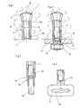
- the expansion anchor according to Figure 1 consists of the stud bolt 1 with a conical expansion cone 2, and the expansion sleeve 4 provided with longitudinal slots 3 over part of its length.
- the inner bore of the expansion sleeve 4 has two sections, the section 5 a in the area of the slotted part the expansion sleeve corresponds in diameter to the shaft 6 of the stud 1. This section 5 a is followed by an enlarged section 5 b extending to the front end of the expansion sleeve 4.
- the expansible plug the latter is in the with an undercut 7 prepared 'drilling. Hole 8 used in the masonry 9 and spread by expanding the expansion sleeve 4 on the stud bolt 1 supported on the bottom of the borehole. Then, according to FIG.
- the adapter piece 11 is screwed onto the thread 10 of the stud bolt 1 ending within the expansion sleeve 4, which has an internal thread 12 for this purpose.
- the larger cross section of the adapter piece 11 compared to the stud bolt 1 results in a.
- the adapter piece 11 a according to FIG. 3 has a continuous internal thread 12 which is adapted to the thread 10 of the stud bolt 1.
- the expansion anchor is therefore also suitable for fastening threaded rods 16 or fastening screws.
- FIG. 4 shows an adapter piece 11b, the connecting part of which is designed as a tab 17, in which an opening 18 suitable for hanging tapes or wires is arranged.
Abstract
Description
- Die Erfindung betrifft einen Spreizdübel für die Verankerung in konisch nach innen erweitert hergestellten Bohrlö- _ehern, bestehend aus einem am Bohrlochgrund sich abstützenden, einen Spreizkonus aufweisenden Stehbolzen mit Außengewinde, auf dessen Spreizkonus eine über einen Teil ihrer Länge mit Längsschlitzen versehene Spreizhülse auftreibbar ist.
- Durch konisch erweiterte Bohrlöcher ist es möglich, nahezu spreizdruckfreie Verankerungen durchzuführen, die aufgrund der erhöhten Aufspreizung des Befestigungselementes zusätzlich noch höhere Haltewerte erbringen. Allerdings sind zur Herstellung der konischen Bohrlöcher aufwendige Bohrvorrichtungen erforderlich, die die Befestigung mit höheren Kosten belasten.
- Der Erfindung liegt daher die Aufgabe zugrunde, ein Befestigungselement zu schaffen, das bei stets gleichen Haltewerten und gleicher Bohrlochkontur die Möglichkeit bietet, das Anschlußteil in Anpassung an die zu befestigenden Gegenständen zu variieren.
- Erfindungsgemäß wird dies dadurch erreicht, daß der Stehbolzen innerhalb des ungeschlitzten Teils der Spreizhülse endet und auf sein Außengewinde ein mit einem über die Oberfläche des Mauerwerks überragenden Anschlußteil versehenes Adapterstück aufschraubbar ist, wobei der Durchmesser der Innenbohrung der Spreizhülse zumindest im Bereich des geschlitzten Teils dem Schaft des Stehbolzens und im Anschluß daran bis zur Stirnseite der Spreizhülse dem Schaft des Adapterstückes angepaßt ist.
- Durch die erfindungsgemäße Lösung ergibt sich im Bereich des geschlitzten Teils der Spreizhülse eine dickere Wandungsstärke, die eine vollständige Ausfüllung der Hinterschneidung des Bohrloches und damit hohe Haltewerte ermöglicht. Die Aufbohrung im Bereich des ungeschlitzten Teils der Spreizhülse ergibt einen Spalt zwischen dem Schaft des Stehbolzens und der Wandung der Innenbohrung der Spreizhülse, so daß das Aufschrauben eines Adapterstückes auf das Außengewinde des innerhalb des ungeschlitzten Teils der Spreizhülse endenden Stehbolzens möglich ist. Das über die Stirnseite der Spreizhülse und der Oberfläche des Mauerwerks hinausragende Anschlußteil des Adapterstückes kann in Anpassung an den zu befestigenden Gegenstand variiert werden.
- In Ergänzung der Erfindung kann dieses Anschlußteil bspw. als Außengewinde ausgebildet sein, dessen Außendurchmesser größer ist als der Gewindeaußendurchmesser des Stehbolzens. Ferner besteht auch die Möglichkeit, das zum Aufschrauben auf das Außengewinde des Stehbolzens notwendige Innengewinde durch das Adapterstück durchgehen zu lassen, so daß von der gegenüberliegenden Seite des Adapterstückes eine Befe- .stigungsschraube, Gewindestange oder dgl. einschraubbar ist. Ebenso kann das Anschlußteil als Lasche ausgebildet sein, um Drähte, Lochbänder oder dgl. einzuhängen.
- In der Zeichnung sind Ausführungsbeispiele der Erfindung dargestellt. Es zeigen:
- Figur 1 das Befestigungselement in verankertem Zustand
- Figur 2 das Befestigungselement mit aufgeschraubtem Adapterstück
- Figur 3 ein Adapterstück mit Innengewinde
- Figur 4 ein Adapterstück mit Lasche.
- Der Spreizdübel nach Figur 1 besteht aus dem Stehbolzen 1 mit kegelförmigem Spreizkonus 2, und der über einen Teil ihrer Länge mit Längsschlitzen 3 versehenen Spreizhülse 4. Die Innenbohrung der Spreizhülse 4 weist zwei Abschnitte auf, wobei der Abschnitt 5 a im Bereich des geschlitzten.Teils der Spreizhülse im Durchmesser dem Schaft 6 des Stehbolzens 1 entspricht. An diesen Abschnitt 5 a schließt sich ein bis zum Stirnende der Spreizhülse 4 sich erstreckender erweiterter Abschnitt 5 b an. Zur Verankerung des Spreizdübels wird dieser in das mit einer Hinterschneidung 7 vorbereitete'Bohr- . loch 8 im Mauerwerk 9 eingesetzt und durch Auftreiben der Spreizhülse 4 auf den am Bohrlochgrund sich abstützenden Stehbolzen 1 aufgespreizt. Danach wird gemäß Figur 2 auf das Gewinde 10 des innerhalb der Spreizhülse 4 endenden Stehbolzens 1 das Adapterstück 11 aufgeschraubt, das zu diesem Zweck ein Innengewinde 12 aufweist. Das als Außengewinde 13 ausgebildete, die Oberfläche des Mauerwerks überragende Anschlußteil des Adapterstückes 11 dient zur Befestigung eines Gegenstandes 14 mittels einer Mutter 15. Durch den gegenüber dem Stehbolzen 1 größeren Querschnitt des Adapterstückes 11 ergibt sich eine .höhere Querkraftaufnahme für den zu befestigenden Gegenstand.
- Das Adapterstück 11 a gemäß Figur 3 weist ein durchgehendes, dem Gewinde 10 des Stehbolzens 1 angepaßtes Innengewinde 12 auf. Damit ist der Spreizdübel auch für die Befestigung von Gewindestangen 16 oder Befestigungsschrauben geeignet.
- Figur 4 zeigt ein Adapterstück 11 b, dessen Anschlußteil als Lasche 17 ausgebildet ist, in der ein zum Einhängen von Bändern oder Drähten geeigneter Durchbruch 18 angeordnet ist.
Claims (2)
Priority Applications (1)
| Application Number | Priority Date | Filing Date | Title |
|---|---|---|---|
| AT82100464T ATE13337T1 (de) | 1981-03-24 | 1982-01-23 | Spreizduebel fuer die verankerung in konisch nach innen erweitert hergestellten bohrloechern. |
Applications Claiming Priority (2)
| Application Number | Priority Date | Filing Date | Title |
|---|---|---|---|
| DE19813111504 DE3111504A1 (de) | 1981-03-24 | 1981-03-24 | Spreizduebel fuer die verankerung in konisch nach innen erweitert hergestellten bohrloechern |
| DE3111504 | 1981-03-24 |
Publications (2)
| Publication Number | Publication Date |
|---|---|
| EP0060973A1 true EP0060973A1 (de) | 1982-09-29 |
| EP0060973B1 EP0060973B1 (de) | 1985-05-15 |
Family
ID=6128137
Family Applications (1)
| Application Number | Title | Priority Date | Filing Date |
|---|---|---|---|
| EP82100464A Expired EP0060973B1 (de) | 1981-03-24 | 1982-01-23 | Spreizdübel für die Verankerung in konisch nach innen erweitert hergestellten Bohrlöchern |
Country Status (9)
| Country | Link |
|---|---|
| EP (1) | EP0060973B1 (de) |
| JP (1) | JPS57171106A (de) |
| AT (1) | ATE13337T1 (de) |
| BR (1) | BR8201517A (de) |
| DE (1) | DE3111504A1 (de) |
| DK (1) | DK126582A (de) |
| ES (1) | ES263924Y (de) |
| GR (1) | GR76334B (de) |
| HU (1) | HU186916B (de) |
Cited By (1)
| Publication number | Priority date | Publication date | Assignee | Title |
|---|---|---|---|---|
| US4943195A (en) * | 1987-06-13 | 1990-07-24 | Fischerwerke Artur Fischer Gmbh & Co. Kg | Expansible anchoring plug assembly |
Families Citing this family (10)
| Publication number | Priority date | Publication date | Assignee | Title |
|---|---|---|---|---|
| DE3134876A1 (de) * | 1981-09-03 | 1983-03-17 | Artur Dr.H.C. 7244 Waldachtal Fischer | Spreizduebel fuer die verankerung in konisch nach innen erweitert hergestellten bohrloechern |
| EP0163120B1 (de) * | 1984-05-29 | 1988-06-08 | Fischerwerke Arthur Fischer GmbH & Co. KG | Spreizdübel |
| DE3921697A1 (de) * | 1989-07-01 | 1991-01-10 | Fischer Artur Werke Gmbh | Verankerung eines gewindebolzens mittels einer verbundmasse |
| DE3926229A1 (de) * | 1989-08-09 | 1991-02-14 | Fischer Artur Werke Gmbh | Spreizduebel |
| DE3930789A1 (de) * | 1989-09-14 | 1991-03-28 | Fischer Artur Werke Gmbh | Spreizduebel |
| DE3933694A1 (de) * | 1989-09-14 | 1991-06-06 | Fischer Artur Werke Gmbh | Spreizduebel |
| DE4400895A1 (de) * | 1994-01-14 | 1995-07-20 | Fischer Artur Werke Gmbh | Spreizdübel sowie Montageverfahren und Setzeinrichtung zu dessen Verankerung in einem Mauerwerk |
| DE19507058A1 (de) * | 1995-01-28 | 1996-08-01 | Heinrich Liebig | Formschlüssig setzbarer Hinterschnitt-Anker |
| DE10308807A1 (de) * | 2003-02-27 | 2004-09-09 | Janicon Ag | Versenkbarer Multifunktionsanker |
| CN102168707A (zh) * | 2011-04-25 | 2011-08-31 | 济南纳诺精密机械有限公司 | 一种内置螺栓式膨胀螺丝 |
Citations (6)
| Publication number | Priority date | Publication date | Assignee | Title |
|---|---|---|---|---|
| GB866258A (en) * | 1956-06-07 | 1961-04-26 | Seetru Ltd | Improvements in anchorage plug appliances |
| CH353879A (fr) * | 1958-07-11 | 1961-04-30 | Seetru Ltd | Dispositif d'ancrage et procédé de mise en action de ce dispositif |
| FR2085076A5 (de) * | 1970-03-26 | 1971-12-17 | Celmac Ag | |
| DE7125107U (de) * | 1972-01-27 | Langensiepen M Kg | Befestigungsvorrichtung mit einem Halteelement und einem Dübel | |
| DE2437308A1 (de) * | 1974-08-02 | 1976-02-12 | Upat Max Langensiepen Kg | Befestigungsvorrichtung fuer leichtbauplatten oder dergleichen |
| DE2833077A1 (de) * | 1977-07-29 | 1979-02-08 | Aerpat Ag | Widerhaken, insbesondere fuer befestigungsmittel und verfahren zu dessen herstellung |
Family Cites Families (2)
| Publication number | Priority date | Publication date | Assignee | Title |
|---|---|---|---|---|
| JPS521012Y2 (de) * | 1971-08-17 | 1977-01-11 | ||
| DE2613499A1 (de) * | 1976-03-30 | 1977-10-13 | Heinrich B Schaefers | Bauwerksanker und verfahren zu seinem verankern |
-
1981
- 1981-03-24 DE DE19813111504 patent/DE3111504A1/de not_active Withdrawn
-
1982
- 1982-01-23 AT AT82100464T patent/ATE13337T1/de not_active IP Right Cessation
- 1982-01-23 EP EP82100464A patent/EP0060973B1/de not_active Expired
- 1982-02-01 GR GR67176A patent/GR76334B/el unknown
- 1982-03-16 ES ES1982263924U patent/ES263924Y/es not_active Expired
- 1982-03-19 BR BR8201517A patent/BR8201517A/pt unknown
- 1982-03-22 DK DK126582A patent/DK126582A/da not_active Application Discontinuation
- 1982-03-24 HU HU82895A patent/HU186916B/hu unknown
- 1982-03-24 JP JP57045751A patent/JPS57171106A/ja active Pending
Patent Citations (6)
| Publication number | Priority date | Publication date | Assignee | Title |
|---|---|---|---|---|
| DE7125107U (de) * | 1972-01-27 | Langensiepen M Kg | Befestigungsvorrichtung mit einem Halteelement und einem Dübel | |
| GB866258A (en) * | 1956-06-07 | 1961-04-26 | Seetru Ltd | Improvements in anchorage plug appliances |
| CH353879A (fr) * | 1958-07-11 | 1961-04-30 | Seetru Ltd | Dispositif d'ancrage et procédé de mise en action de ce dispositif |
| FR2085076A5 (de) * | 1970-03-26 | 1971-12-17 | Celmac Ag | |
| DE2437308A1 (de) * | 1974-08-02 | 1976-02-12 | Upat Max Langensiepen Kg | Befestigungsvorrichtung fuer leichtbauplatten oder dergleichen |
| DE2833077A1 (de) * | 1977-07-29 | 1979-02-08 | Aerpat Ag | Widerhaken, insbesondere fuer befestigungsmittel und verfahren zu dessen herstellung |
Cited By (1)
| Publication number | Priority date | Publication date | Assignee | Title |
|---|---|---|---|---|
| US4943195A (en) * | 1987-06-13 | 1990-07-24 | Fischerwerke Artur Fischer Gmbh & Co. Kg | Expansible anchoring plug assembly |
Also Published As
| Publication number | Publication date |
|---|---|
| DE3111504A1 (de) | 1982-10-14 |
| ES263924U (es) | 1982-11-01 |
| HU186916B (en) | 1985-10-28 |
| ES263924Y (es) | 1983-05-01 |
| ATE13337T1 (de) | 1985-06-15 |
| EP0060973B1 (de) | 1985-05-15 |
| DK126582A (da) | 1982-09-25 |
| GR76334B (de) | 1984-08-04 |
| BR8201517A (pt) | 1983-02-08 |
| JPS57171106A (en) | 1982-10-21 |
Similar Documents
| Publication | Publication Date | Title |
|---|---|---|
| EP0905385B1 (de) | Spreizdübel | |
| DE3426994C2 (de) | ||
| EP0067941B1 (de) | Spreizdübel für die Verankerung in konisch nach innen erweitert hergestellten Bohrlöchern | |
| EP0314912B1 (de) | Spreizdübel für die Verankerung in hinterschnittenen Bohrlöchern | |
| EP0247282A2 (de) | Dübel aus Kunststoff | |
| DE3111361A1 (de) | Spreizankerschraubvorrichtung | |
| DE3818652A1 (de) | Spreizduebel aus kunststoff | |
| EP0060973B1 (de) | Spreizdübel für die Verankerung in konisch nach innen erweitert hergestellten Bohrlöchern | |
| EP0249731B1 (de) | Schlagspreizdübel | |
| EP0163120B1 (de) | Spreizdübel | |
| DE3345331A1 (de) | Spreiznagel | |
| DE2135333A1 (de) | Befestigungselement fuer die verankerung in einem bohrloch in bewehrtem beton insbesondere zur befestigung abgehaengter decken, rohre oder dgl | |
| DE2849140A1 (de) | Spreizduebel zur abstandsbefestigung von verkleidungselementen o.dgl. | |
| DE3205928A1 (de) | Schlagspreizduebel fuer die verankerung in insbesondere konisch nach innen erweiterten bohrloechern | |
| EP0195188A1 (de) | Spreizdübel für die Verankerung in konisch nach innen erweitert hergestellten Bohrlöchern | |
| EP0377820A1 (de) | Spreizdübel für die Verankerung in einem Bohrloch eines Mauerwerks | |
| DE3411431C2 (de) | ||
| EP0158049B1 (de) | Spreizdübel | |
| DE2914074A1 (de) | Bauwerksanker fuer eine verankerung in einer bohrung | |
| EP0250783A1 (de) | Spreizdübel | |
| DE3538298A1 (de) | Schlagspreizduebel fuer die verankerung in konisch nach innen erweiterten bohrloechern | |
| DE2650713A1 (de) | Spreizbolzen | |
| DE2900698A1 (de) | Einsatzstueck fuer einen duebel | |
| DE2711605C2 (de) | Dübel | |
| DE3716298A1 (de) | Schlaganker |
Legal Events
| Date | Code | Title | Description |
|---|---|---|---|
| PUAI | Public reference made under article 153(3) epc to a published international application that has entered the european phase |
Free format text: ORIGINAL CODE: 0009012 |
|
| AK | Designated contracting states |
Designated state(s): AT BE CH FR GB IT NL SE |
|
| 17P | Request for examination filed |
Effective date: 19830210 |
|
| ITF | It: translation for a ep patent filed |
Owner name: ING. ZINI MARANESI & C. S.R.L. |
|
| GRAA | (expected) grant |
Free format text: ORIGINAL CODE: 0009210 |
|
| AK | Designated contracting states |
Designated state(s): AT BE CH FR GB IT LI NL SE |
|
| REF | Corresponds to: |
Ref document number: 13337 Country of ref document: AT Date of ref document: 19850615 Kind code of ref document: T |
|
| ET | Fr: translation filed | ||
| BECH | Be: change of holder |
Free format text: 850515 *FISCHER-WERKE ARTUR FISCHER G.M.B.H. |
|
| PLBE | No opposition filed within time limit |
Free format text: ORIGINAL CODE: 0009261 |
|
| STAA | Information on the status of an ep patent application or granted ep patent |
Free format text: STATUS: NO OPPOSITION FILED WITHIN TIME LIMIT |
|
| 26N | No opposition filed | ||
| REG | Reference to a national code |
Ref country code: CH Ref legal event code: PUE Owner name: FISCHER-WERKE ARTUR FISCHER GMBH & CO. KG |
|
| ITPR | It: changes in ownership of a european patent |
Owner name: CESSIONE;FISCHER WERKE ARTUR FISCHER GMBH & CO. KG |
|
| REG | Reference to a national code |
Ref country code: FR Ref legal event code: TP |
|
| NLS | Nl: assignments of ep-patents |
Owner name: FISCHER-WERKE ARTUR FISCHER GMBH & CO. KG. TE WALD |
|
| REG | Reference to a national code |
Ref country code: GB Ref legal event code: 732 |
|
| PGFP | Annual fee paid to national office [announced via postgrant information from national office to epo] |
Ref country code: NL Payment date: 19890131 Year of fee payment: 10 |
|
| PGFP | Annual fee paid to national office [announced via postgrant information from national office to epo] |
Ref country code: CH Payment date: 19900110 Year of fee payment: 9 |
|
| PGFP | Annual fee paid to national office [announced via postgrant information from national office to epo] |
Ref country code: SE Payment date: 19900118 Year of fee payment: 9 |
|
| PGFP | Annual fee paid to national office [announced via postgrant information from national office to epo] |
Ref country code: AT Payment date: 19900123 Year of fee payment: 9 |
|
| PGFP | Annual fee paid to national office [announced via postgrant information from national office to epo] |
Ref country code: BE Payment date: 19900124 Year of fee payment: 9 |
|
| PG25 | Lapsed in a contracting state [announced via postgrant information from national office to epo] |
Ref country code: AT Effective date: 19910123 |
|
| PG25 | Lapsed in a contracting state [announced via postgrant information from national office to epo] |
Ref country code: SE Effective date: 19910124 |
|
| ITTA | It: last paid annual fee | ||
| PG25 | Lapsed in a contracting state [announced via postgrant information from national office to epo] |
Ref country code: CH Effective date: 19910131 Ref country code: LI Effective date: 19910131 Ref country code: BE Effective date: 19910131 |
|
| PG25 | Lapsed in a contracting state [announced via postgrant information from national office to epo] |
Ref country code: NL Effective date: 19910801 |
|
| NLV4 | Nl: lapsed or anulled due to non-payment of the annual fee | ||
| REG | Reference to a national code |
Ref country code: CH Ref legal event code: PL |
|
| PGFP | Annual fee paid to national office [announced via postgrant information from national office to epo] |
Ref country code: FR Payment date: 19921027 Year of fee payment: 12 |
|
| PGFP | Annual fee paid to national office [announced via postgrant information from national office to epo] |
Ref country code: GB Payment date: 19921102 Year of fee payment: 12 |
|
| PG25 | Lapsed in a contracting state [announced via postgrant information from national office to epo] |
Ref country code: GB Effective date: 19940123 |
|
| GBPC | Gb: european patent ceased through non-payment of renewal fee |
Effective date: 19940123 |
|
| PG25 | Lapsed in a contracting state [announced via postgrant information from national office to epo] |
Ref country code: FR Effective date: 19940930 |
|
| REG | Reference to a national code |
Ref country code: FR Ref legal event code: ST |
|
| EUG | Se: european patent has lapsed |
Ref document number: 82100464.5 Effective date: 19910910 |