EP0059873A1 - Einrichtung zur Entnahme von Druckexemplaren aus den Schaufelrädern eines Falzapparates - Google Patents
Einrichtung zur Entnahme von Druckexemplaren aus den Schaufelrädern eines Falzapparates Download PDFInfo
- Publication number
- EP0059873A1 EP0059873A1 EP82101350A EP82101350A EP0059873A1 EP 0059873 A1 EP0059873 A1 EP 0059873A1 EP 82101350 A EP82101350 A EP 82101350A EP 82101350 A EP82101350 A EP 82101350A EP 0059873 A1 EP0059873 A1 EP 0059873A1
- Authority
- EP
- European Patent Office
- Prior art keywords
- wheels
- stop
- stops
- paddle wheels
- wheel
- Prior art date
- Legal status (The legal status is an assumption and is not a legal conclusion. Google has not performed a legal analysis and makes no representation as to the accuracy of the status listed.)
- Granted
Links
- 230000005540 biological transmission Effects 0.000 claims description 2
- 230000015572 biosynthetic process Effects 0.000 claims description 2
- 230000002093 peripheral effect Effects 0.000 abstract description 7
- 230000036461 convulsion Effects 0.000 description 1
- 238000011161 development Methods 0.000 description 1
- 230000018109 developmental process Effects 0.000 description 1
- 238000012423 maintenance Methods 0.000 description 1
Images


Classifications
-
- B—PERFORMING OPERATIONS; TRANSPORTING
- B65—CONVEYING; PACKING; STORING; HANDLING THIN OR FILAMENTARY MATERIAL
- B65H—HANDLING THIN OR FILAMENTARY MATERIAL, e.g. SHEETS, WEBS, CABLES
- B65H29/00—Delivering or advancing articles from machines; Advancing articles to or into piles
- B65H29/66—Advancing articles in overlapping streams
- B65H29/6609—Advancing articles in overlapping streams forming an overlapping stream
-
- B—PERFORMING OPERATIONS; TRANSPORTING
- B65—CONVEYING; PACKING; STORING; HANDLING THIN OR FILAMENTARY MATERIAL
- B65H—HANDLING THIN OR FILAMENTARY MATERIAL, e.g. SHEETS, WEBS, CABLES
- B65H29/00—Delivering or advancing articles from machines; Advancing articles to or into piles
- B65H29/38—Delivering or advancing articles from machines; Advancing articles to or into piles by movable piling or advancing arms, frames, plates, or like members with which the articles are maintained in face contact
- B65H29/40—Members rotated about an axis perpendicular to direction of article movement, e.g. star-wheels formed by S-shaped members
-
- B—PERFORMING OPERATIONS; TRANSPORTING
- B65—CONVEYING; PACKING; STORING; HANDLING THIN OR FILAMENTARY MATERIAL
- B65H—HANDLING THIN OR FILAMENTARY MATERIAL, e.g. SHEETS, WEBS, CABLES
- B65H29/00—Delivering or advancing articles from machines; Advancing articles to or into piles
- B65H29/68—Reducing the speed of articles as they advance
-
- B—PERFORMING OPERATIONS; TRANSPORTING
- B65—CONVEYING; PACKING; STORING; HANDLING THIN OR FILAMENTARY MATERIAL
- B65H—HANDLING THIN OR FILAMENTARY MATERIAL, e.g. SHEETS, WEBS, CABLES
- B65H2301/00—Handling processes for sheets or webs
- B65H2301/40—Type of handling process
- B65H2301/44—Moving, forwarding, guiding material
- B65H2301/447—Moving, forwarding, guiding material transferring material between transport devices
- B65H2301/4473—Belts, endless moving elements on which the material is in surface contact
- B65H2301/44732—Belts, endless moving elements on which the material is in surface contact transporting articles in overlapping stream
-
- B—PERFORMING OPERATIONS; TRANSPORTING
- B65—CONVEYING; PACKING; STORING; HANDLING THIN OR FILAMENTARY MATERIAL
- B65H—HANDLING THIN OR FILAMENTARY MATERIAL, e.g. SHEETS, WEBS, CABLES
- B65H2301/00—Handling processes for sheets or webs
- B65H2301/40—Type of handling process
- B65H2301/44—Moving, forwarding, guiding material
- B65H2301/447—Moving, forwarding, guiding material transferring material between transport devices
- B65H2301/44765—Rotary transport devices with compartments
-
- B—PERFORMING OPERATIONS; TRANSPORTING
- B65—CONVEYING; PACKING; STORING; HANDLING THIN OR FILAMENTARY MATERIAL
- B65H—HANDLING THIN OR FILAMENTARY MATERIAL, e.g. SHEETS, WEBS, CABLES
- B65H2404/00—Parts for transporting or guiding the handled material
- B65H2404/60—Other elements in face contact with handled material
- B65H2404/65—Other elements in face contact with handled material rotating around an axis parallel to face of material and perpendicular to transport direction, e.g. star wheel
- B65H2404/657—Means for varying the space between the elements
Definitions
- the invention relates to a device for removing printed copies from the rotating paddle wheels of a folder, which are spaced apart from one another on an axis.
- DE-Laid-Open Specification 28 11 467 has already disclosed a device for forming a shingled stream of folded printed products.
- This device essentially comprises a chain equipped with grippers, which is guided between two disks of a paddle wheel of a folder. With this device, the printed copies can inevitably be led out of the paddle wheel and transferred to a conveyor belt arranged underneath this with a predetermined scale spacing. By removing the printed copies directly from the bucket wheels using the chains equipped with grippers, gentle transfer with a constant scale spacing is difficult since the grippers have to remove the printed copies from the rotating blades. Should the printed copies on a continuously rotating transport device, for. B. a tape to be passed to form a stream of shingles, is so the exact maintenance of the desired scale spacing due to the uncontrolled slipping out of the paddle wheels is practically impossible.
- the object of the invention is to design a device of the type specified at the outset with a simple device by means of which printed copies can be gently pushed out of the impeller with a precisely definable scale spacing.
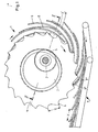
- Figures 1 and 2 show an arrangement consisting of several paddle wheels 1, 1 '.
- the paddle wheels 1, 1 ' are spaced apart from one another on an axis 2 arranged.
- a stationary disc 3, 3' with respect to the axis 2 is provided.
- This carries stop wheels 4, 4 'each, which have an internal toothing and can be driven with a predetermined transmission ratio via external toothed drive gears 5 located on the axis 2.
- the stop wheels 4, 4 ' have stops 6 in the form of teeth, the distance x of which corresponds to the desired scale distance.
- a conveyor belt 7 is shown, on which the printed copies 8 pushed out of the paddle wheels 1, 1' are to be placed with the predetermined scale spacing x.
- the print copies entering the blades 9 from a folding device are aligned by the stops 6 due to the eccentric arrangement of the stop wheels 4, 4 'and the lower peripheral speed of the stops 6 in relation to the peripheral speed of the blades 9. Due to the rotation of the paddle wheels 1, 1 'and the stop wheels 4, 4', the printed copies 8 are pushed out of the blades 9 through the stops 6 in the lower region and reach the conveyor belt 7 with a predetermined scale distance x. Since the speed of the conveyor belt 7 is the same the circumferential speed of the stops 6, the scale spacing x predetermined by the stop wheels 4, 4 'is maintained even when the printed copies 8 are transported away by the conveyor belt 7.
- the direction of rotation of the paddle wheels 1, 1 ', the stop wheels 4, 4' and the conveyor belt 7 is in each case indicated by an arrow.
- Fig. 1 shows that due to the eccentric arrangement of the stop wheels 4, 4 'based on the paddle wheels 1, 1' and the lower peripheral speed of the stop wheels 4, 4 'compared to the peripheral speed of the blades 9 of the paddle wheels 1, 1' initially a printed copy 8 entering a blade 9 will run onto a stop 6, as a result of which the printed copy 8 is aligned. This alignment is gentle, since there is a comparatively small difference in peripheral speed between stop wheels 4, 4 'and paddle wheels 1, 1'.
- the printed copy aligned with the scale spacing x is pushed out of the paddle wheels 1, 1 'by a stop 6 and placed on the conveyor belt 7 arranged underneath.
- This transfer of the printed copies 8 to the conveyor belt 7 also takes place without any problems, since, as already mentioned, the speed of the conveyor belt 7 is equal to the peripheral speed of the stop wheels 4, 4 '.
- FIG. 1 For better understanding of the mode of operation of the device according to the invention, three printed copies with 8, 8 ', 8 "in different positions are shown by way of example in FIG. 1, the printed copy 8 initially running into the blade 9 and the printed copy 8' in the blade 9 ', is then aligned with a stop 6, after which it is shown how a printed copy 8 "with the removal of the blade 9" is pushed upwards out of the blade wheels 1, 1 'by an assigned stop 6 and to the one below lying conveyor belt 7 is given.
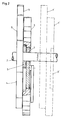
- FIGS. 1 and 2 show a second embodiment in which the basic structure and the principle of operation of the embodiment according to FIGS. 1 and 2 can be found again.
- grippers 10 are provided here at the stops. These are controlled by roller levers 11, the rollers 12 of which run on a fixed control cam 13. As can be seen in FIG. 4, the control curve can be generated by appropriate formation of the fixed disk 3.
- the grippers 14 of the transport device 15 no longer need, as in the case of known devices, to "engage” in the paddle wheels 1 in order to get the printed copy 8 out.
- D is a print copies 8 held by the grippers 10, a lateral arrangement of the transport apparatus 15 readily possible.
Landscapes
- Engineering & Computer Science (AREA)
- Mechanical Engineering (AREA)
- Discharge By Other Means (AREA)
- Separation, Sorting, Adjustment, Or Bending Of Sheets To Be Conveyed (AREA)
Abstract
Description
- Die Erfindung betrifft eine Vorrichtung zur Entnahme von Druckexemplaren aus den auf einer Achse angeordneten voneinander beabstandeten rotierenden Schaufelrädern eines Falzapparates.
- Durch die DE-Offenlegungsschrift 28 11 467 ist bereits eine Einrichtung zur Bildung eines Schuppenstromes von gefalzten Druckprodukten bekannt geworden. Diese Einrichtung umfaßt im wesentlichen eine mit Greifern ausgerüstete Kette, die zwischen zwei Scheiben eines Schaufelrades eines Falzapparates geführt ist. Mit dieser Einrichtung können die Druckexemplare zwangsläufig aus dem Schaufelrad herausgeführt und an ein unter diesem angeordnetes Transportband mit vorgegebenem Schuppenabstand übergeben werden. Durch die Entnahme der Druckexemplare mittels der mit Greifern ausgerüsteten Ketten direkt aus den Schaufelrädern ist eine schonende Übergabe mit einem gleichbleibenden Schuppenabstand schwierig, da die Greifer die Druckexemplare aus den rotierenden Schaufeln entnehmen müssen. Sollen die Druckexemplare auf eine kontinuierlich umlaufende Transportvorrichtung, z. B. ein Band, unter Bildung eines Schuppenstromes übergeben werden, so ist die exakte Einhaltung des gewünschten Schuppenabstandes infolge des unkontrollierten Herausrutschvorganges aus den Schaufelrädern praktisch nicht möglich.
- Aufgabe der Erfindung ist es, eine Vorrichtung der eingangs spezifizierten Gattung mit einer einfachen Einrichtung auszugestalten, durch die Druckexemplare schonend aus dem Schaufelrad mit einem exakt definierbaren Schuppenabstand herausschiebbar sind.
- Diese Aufgabe wird gemäß dem Kennzeichen des Anspruches 1 gelöst. Vorteilhafte Weiterbildungen der Erfindung ergeben sich aus den Unteransprüchen und aus der Beschreibung in Verbindung mit den Zeichnungen.
- Im folgenden wird die Erfindung anhand zweier Ausführungsbeispiele unter Bezugnahme auf die beiliegenden Zeichnungen im einzelnen beschrieben. In diesen zeigen:
- Fig. 1 eine schematische Seitenansicht der erfindungsgemäßen Einrichtung zur Entnahme von Druckexemplaren,
- Fig. 2 eine Vorderansicht der Einrichtung gemäß Fig. 1,
- Fig. 3 eine schematische Seitenansicht eines zweiten Ausführungsbeispiels und
- Fig. 4 eine Vorderansicht der Einrichtung gemäß Fig. 3.
- Die Figuren 1 und 2 zeigen eine aus mehreren Schaufelrädern 1, 1' bestehende Anordnung. Die Schaufelräder 1, 1' sind voneinander beabstandet auf einer Achse 2 angeordnet. Vorzugsweise ist neben einem jeden Schaufelrad 1, 1' eine ortsfeste bezogen auf die Achse 2 exzentrische Scheibe 3, 3' vorgesehen. Diese trägt jeweils Anschlagräder 4, 4', welche eine Innenverzahnung aufweisen und über auf der Achse 2 sitzende außen verzahnte Antriebszahnräder 5 mit einem vorgegebenen übersetzungsverhältnis antreibbar sind. Am Umfang tragen die Anschlagräder 4, 4' Anschläge 6 in Form von Zacken, deren Abstand x dem gewünschten Schuppenabstand entspricht.
- Unterhalb der Schaufelräder 1, 1' ist ein Transportband 7 gezeigt, auf das die aus den Schaufelrädern 1, 1' herausgeschobenen Druckexemplare 8 mit dem vorgegebenen Schuppenabstand x abzulegen sind.
- Die aus einer Falzvorrichtung (nicht gezeigt) in die Schaufeln 9 einlaufenden Druckexemplare werden durch die Anschläge 6 infolge der exzentrischen Anordnung der Anschlagräder 4, 4' und der geringeren Umfangsgeschwindigkeit der Anschläge 6 bezogen auf die Umfangsgeschwindigkeit der Schaufeln 9 ausgerichtet. Durch die Rotation der Schaufelräder 1, 1' und der Anschlagräder 4, 4' werden im unteren Bereich die Druckexemplare 8 durch die Anschläge 6 aus den Schaufeln 9 herausgeschoben und gelangen mit vorgegebenem Schuppenabstand x auf das Transportband 7. Da die Geschwindigkeit des Transportbandes 7 gleich der Umfangsgeschwindigkeit der Anschläge 6 ist, wird auch beim Abtransport der Druckexemplare 8 durch das Transportband 7 der durch die Anschlagräder 4, 4' vorgegebene Schuppenabstand x beibehalten.
- Die Drehrichtung der Schaufelräder 1, 1', der Anschlagräder 4, 4' sowie des Transportbandes 7 ist jeweils durch einen Pfeil angedeutet.
- Fig. 1 läßt erkennen, daß infolge der exzentrischen Anordnung der Anschlagräder 4, 4' bezogen auf die Schaufelräder 1, 1' und der geringeren Umfangsgeschwindigkeit der Anschlagräder 4, 4' im Vergleich zu der Umfangsgeschwindigkeit der Schaufeln 9 der Schaufelräder 1, 1' zunächst ein in eine Schaufel 9 einlaufendes Druckexemplar 8 auf einen Anschlag 6 auflaufen wird, wodurch eine Ausrichtung des Druckexemplares 8 erfolgt. Diese Ausrichtung geht schonend vor sich, da eine verhältnismäßig geringe Umfangsgeschwindigkeitsdifferenz zwischen Anschlagrädern 4, 4' und Schaufelrädern 1, 1' besteht.
- Wie Fig. 1 im unteren Bereich zeigt, wird das auf den - Schuppenabstand x ausgerichtete Druckexemplar durch einen Anschlag 6 aus den Schaufelrädern 1, 1' herausgeschoben und auf das darunter angeordnete Transportband 7 abgelegt. Auch diese übergabe der Druckexemplare 8 an das Transportband 7 erfolgt problemlos, da wie bereits erwähnt, die Geschwindigkeit des Transportbandes 7 gleich der Umfangsgeschwindigkeit der Anschlagräder 4, 4' ist.
- Zum besseren Verständnis der Wirkungsweise der erfindungsgemäßen Einrichtung sind in Fig. 1 beispielhaft drei Druckexemplare mit 8, 8', 8 " in verschiedenen Positionen gezeigt, wobei das Druckexemplar 8 zunächst in die Schaufel 9 einläuft und das Druckexemplar 8' in der Schaufel 9', anschließend an einem Anschlag 6 ausgerichtet wird, wonach gezeigt ist, wie ein Druckexemplar 8" unter Wegziehung der Schaufel 9" nach oben durch einen zugeordneten Anschlag 6 aus den Schaufelrädern 1, 1' herausgeschoben und an das darunter liegende Transportband 7 gegeben wird.
- Fig. 3 und 4 zeigen ein zweites Ausführungsbeispiel, bei dem der Grundaufbau und das grundsätzliche Wirkungsprinzip der Ausführungsform gemäß Fig. 1 und 2 wiederzufinden sind.
- Zusätzlich sind hier an den Anschlägen 6 Greifer 10 vorgesehen. Diese werden von Rollenhebeln 11 gesteuert, deren Rollen 12 auf einer ortsfesten Steuerkurve 13 laufen. Wie Fig. 4 erkennen läßt, kann die Steuerkurve durch entsprechende Ausbildung der ortsfesten Scheibe 3 erzeugt werden.
- Wenn die Vorderkante des in die Schaufel 9 einfallenden Druckexemplares 8 den Anschlag 6 erreicht hat, wird diese durch beim Verschwenken der Rollenhebel 11 einfallende Greifer 10 festgeklemmt und in diesem Zustand aus den Schaufelrädern 1 geschoben. Die Übergabe des herausgeschobenen Druckexemplares 8 erfolgt an die schematisch angedeuteten Greifer 14 einer Transportvorrichtung 15, die z. B. eine Transportkette sein kann. Die Übergabe erfolgt sehr exemplarschonend und mit exakt vorgegebenem Abstand x.
- Die Greifer 14 der Transportvorrichtung 15 brauchen nicht mehr, wie bei bekannten Vorrichtungen, in die Schaufelräder 1 "einzugreifen" um das Druckexemplar 8 herauszuholen.
- Da die Druckexemplare 8 durch die Greifer 10 festgehalten werden, ist eine seitliche Anordnung der Transportvorrichtung 15 ohne weiteres möglich.
Claims (9)
Applications Claiming Priority (2)
| Application Number | Priority Date | Filing Date | Title |
|---|---|---|---|
| DE3108681 | 1981-03-07 | ||
| DE19813108681 DE3108681A1 (de) | 1981-03-07 | 1981-03-07 | "einrichtung zur entnahme von druckexemplaren aus den schaufelraedern eines falzapparates" |
Publications (2)
| Publication Number | Publication Date |
|---|---|
| EP0059873A1 true EP0059873A1 (de) | 1982-09-15 |
| EP0059873B1 EP0059873B1 (de) | 1985-04-24 |
Family
ID=6126590
Family Applications (1)
| Application Number | Title | Priority Date | Filing Date |
|---|---|---|---|
| EP82101350A Expired EP0059873B1 (de) | 1981-03-07 | 1982-02-23 | Einrichtung zur Entnahme von Druckexemplaren aus den Schaufelrädern eines Falzapparates |
Country Status (4)
| Country | Link |
|---|---|
| US (1) | US4434979A (de) |
| EP (1) | EP0059873B1 (de) |
| JP (1) | JPS57160866A (de) |
| DE (2) | DE3108681A1 (de) |
Cited By (8)
| Publication number | Priority date | Publication date | Assignee | Title |
|---|---|---|---|---|
| EP0164440A1 (de) * | 1984-06-14 | 1985-12-18 | Rockwell International Corporation | Schaufelrad für Faltapparat |
| EP0151972A3 (en) * | 1984-02-08 | 1987-08-12 | Albert-Frankenthal Ag | Method and device for delivering sheet-like articles into streams of overlapping articles |
| EP0307889A3 (en) * | 1987-09-17 | 1989-04-19 | Koenig & Bauer Aktiengesellschaft | Device for delivering prints from the paddle wheels of a folding apparatus |
| EP0312749A3 (en) * | 1987-10-23 | 1989-07-12 | Ferag Ag | Method and device for taking over prints from a turning paddle wheel of a printing machine |
| EP0408902A1 (de) * | 1989-07-18 | 1991-01-23 | Ferag AG | Vorrichtung zum Auslegen von Druckereiprodukten |
| EP0638503A1 (de) * | 1993-08-09 | 1995-02-15 | Heidelberger Druckmaschinen Aktiengesellschaft | Vorrichtung für das Verlangsamen von Exemplaren in einem Falzapparat |
| EP0941956A1 (de) * | 1998-03-13 | 1999-09-15 | Heidelberger Druckmaschinen Aktiengesellschaft | Vorrichtung zum flexiblen Führen von transportierten Produkten |
| US6131904A (en) * | 1998-09-01 | 2000-10-17 | Goss Graphic Systems, Inc. | Stripping mechanism for a delivery fly assembly |
Families Citing this family (15)
| Publication number | Priority date | Publication date | Assignee | Title |
|---|---|---|---|---|
| US4565363A (en) * | 1984-05-09 | 1986-01-21 | Custom-Bilt Machinery, Inc. | Apparatus for accurately spacing a sequence of shingled paper sheet products on a conveyor |
| US4620699A (en) * | 1984-07-06 | 1986-11-04 | Savin Corporation | Copy sheet registration assembly for electrophotographic copier |
| DE3515328A1 (de) * | 1985-04-27 | 1986-10-30 | Albert-Frankenthal Ag, 6710 Frankenthal | Auslegevorrichtung |
| DE3826348A1 (de) * | 1988-08-03 | 1990-02-08 | Roland Man Druckmasch | Schaufelradausleger |
| US5040783A (en) * | 1990-09-10 | 1991-08-20 | The Procter & Gamble Company | Rotary stacker |
| US5794929A (en) * | 1993-08-09 | 1998-08-18 | Heidelberger Druckmaschinen Ag | Variable velocity profile decelleration device |
| FR2718723B1 (fr) * | 1994-04-15 | 1996-07-12 | Heidelberg Harris Sa | Dispositif de sortie de cahiers d'une roue à aubes. |
| US6131903A (en) * | 1999-07-20 | 2000-10-17 | Quad/Tech, Inc. | Signature stripping mechanism |
| EP1193201B1 (de) * | 2000-10-02 | 2004-01-28 | Ferag AG | Verfahren und Vorrichtung zur Bildung einer Doppelschuppenformation aus Druckereiprodukten |
| DE10311859B3 (de) * | 2003-03-17 | 2004-08-19 | Nexpress Solutions Llc | Vorrichtung zum Transport eines im wesentlichen bogenförmigen Elementes, insbesondere eines Bedruckstoffbogens |
| US7422212B2 (en) * | 2005-06-21 | 2008-09-09 | Graphic Management Associates, Inc. | Transfer wheel |
| DE102006021361B4 (de) * | 2006-05-08 | 2014-01-23 | Koenig & Bauer Aktiengesellschaft | Auslageeinrichtung zur Auslage von Druckprodukten an einem Falzapparat |
| AU2009208038B2 (en) * | 2008-01-24 | 2013-05-16 | Ferag Ag | Method and device for conveying planar products |
| JP5528099B2 (ja) * | 2009-01-26 | 2014-06-25 | キヤノン株式会社 | シート後処理装置およびこれを備えた画像形成装置 |
| WO2019163038A1 (ja) * | 2018-02-21 | 2019-08-29 | 富士通フロンテック株式会社 | 紙葉類集積装置及び紙葉類集積装置の制御方法 |
Citations (4)
| Publication number | Priority date | Publication date | Assignee | Title |
|---|---|---|---|---|
| DE622611C (de) * | 1934-03-26 | 1935-12-02 | Anciens Etablissements L Chamb | Vorrichtung zum Foerdern von Papierblaettern u. ae. mittels einer gezahnten Radscheibe |
| DE680460C (de) * | 1934-12-28 | 1939-08-30 | Paul Kunze | Bogenauslegevorrichtung |
| US2172364A (en) * | 1937-02-12 | 1939-09-12 | Hoe & Co R | Delivery mechanism |
| DE2811467A1 (de) * | 1977-04-12 | 1978-10-19 | Wifag Maschf | Einrichtung zur bildung eines schuppenstromes von gefalzten druckprodukten |
Family Cites Families (3)
| Publication number | Priority date | Publication date | Assignee | Title |
|---|---|---|---|---|
| US1956541A (en) * | 1931-06-16 | 1934-04-24 | Hoe & Co R | Delivery mechanism for printing machines |
| GB433419A (en) * | 1935-01-02 | 1935-08-14 | Hoe & Co R | Delivery mechanism for use with printing machines |
| US4357126A (en) | 1980-07-10 | 1982-11-02 | H. G. Weber & Co., Inc. | Infeed counting conveyor |
-
1981
- 1981-03-07 DE DE19813108681 patent/DE3108681A1/de not_active Withdrawn
-
1982
- 1982-02-23 DE DE8282101350T patent/DE3263223D1/de not_active Expired
- 1982-02-23 EP EP82101350A patent/EP0059873B1/de not_active Expired
- 1982-03-01 US US06/353,234 patent/US4434979A/en not_active Expired - Lifetime
- 1982-03-05 JP JP57034116A patent/JPS57160866A/ja active Granted
Patent Citations (4)
| Publication number | Priority date | Publication date | Assignee | Title |
|---|---|---|---|---|
| DE622611C (de) * | 1934-03-26 | 1935-12-02 | Anciens Etablissements L Chamb | Vorrichtung zum Foerdern von Papierblaettern u. ae. mittels einer gezahnten Radscheibe |
| DE680460C (de) * | 1934-12-28 | 1939-08-30 | Paul Kunze | Bogenauslegevorrichtung |
| US2172364A (en) * | 1937-02-12 | 1939-09-12 | Hoe & Co R | Delivery mechanism |
| DE2811467A1 (de) * | 1977-04-12 | 1978-10-19 | Wifag Maschf | Einrichtung zur bildung eines schuppenstromes von gefalzten druckprodukten |
Cited By (10)
| Publication number | Priority date | Publication date | Assignee | Title |
|---|---|---|---|---|
| EP0151972A3 (en) * | 1984-02-08 | 1987-08-12 | Albert-Frankenthal Ag | Method and device for delivering sheet-like articles into streams of overlapping articles |
| EP0164440A1 (de) * | 1984-06-14 | 1985-12-18 | Rockwell International Corporation | Schaufelrad für Faltapparat |
| AU573636B2 (en) * | 1984-06-14 | 1988-06-16 | Rockwell International Corp. | Rotary fly conveyor |
| EP0307889A3 (en) * | 1987-09-17 | 1989-04-19 | Koenig & Bauer Aktiengesellschaft | Device for delivering prints from the paddle wheels of a folding apparatus |
| EP0312749A3 (en) * | 1987-10-23 | 1989-07-12 | Ferag Ag | Method and device for taking over prints from a turning paddle wheel of a printing machine |
| US4886264A (en) * | 1987-10-23 | 1989-12-12 | Feraf Ag | Method and apparatus for receiving printed products from a revolvingly driven bucket wheel of a printing machine |
| EP0408902A1 (de) * | 1989-07-18 | 1991-01-23 | Ferag AG | Vorrichtung zum Auslegen von Druckereiprodukten |
| EP0638503A1 (de) * | 1993-08-09 | 1995-02-15 | Heidelberger Druckmaschinen Aktiengesellschaft | Vorrichtung für das Verlangsamen von Exemplaren in einem Falzapparat |
| EP0941956A1 (de) * | 1998-03-13 | 1999-09-15 | Heidelberger Druckmaschinen Aktiengesellschaft | Vorrichtung zum flexiblen Führen von transportierten Produkten |
| US6131904A (en) * | 1998-09-01 | 2000-10-17 | Goss Graphic Systems, Inc. | Stripping mechanism for a delivery fly assembly |
Also Published As
| Publication number | Publication date |
|---|---|
| JPH0154261B2 (de) | 1989-11-17 |
| US4434979A (en) | 1984-03-06 |
| JPS57160866A (en) | 1982-10-04 |
| DE3108681A1 (de) | 1982-09-30 |
| EP0059873B1 (de) | 1985-04-24 |
| DE3263223D1 (en) | 1985-05-30 |
Similar Documents
| Publication | Publication Date | Title |
|---|---|---|
| EP0059873B1 (de) | Einrichtung zur Entnahme von Druckexemplaren aus den Schaufelrädern eines Falzapparates | |
| DE3508416C2 (de) | ||
| DE2809226A1 (de) | Faltmaschine fuer papierbogen | |
| EP0303053B1 (de) | Vorrichtung zur Übergabe von Bogen | |
| DE4201411A1 (de) | Niederhalter an behandlungsanlagen, insbesondere stanzmaschinen, fuer duenne flache gegenstaende, insbesondere boegen aus papier | |
| EP0208081A1 (de) | Verfahren und Vorrichtung zum Öffnen von ausserhalb der Mitte gefalteten Druckprodukten | |
| DE2823247C2 (de) | Einrichtung zur Umlenkung eines aus bogenförmigen Produkten bestehenden Produktstroms | |
| DE3023533C2 (de) | Vorrichtung zum Ablegen von Bogen in einem Stapel | |
| EP0677471B1 (de) | Vorrichtung zur Auslage von Exemplaren aus einem Schaufelrad | |
| EP0429884A1 (de) | Falzapparat für eine Druckmaschine | |
| EP0417622A1 (de) | Verfahren und Vorrichtung zum Transportieren von in Schuppenformation anfallenden Druckereiprodukten | |
| CH662330A5 (de) | Einrichtung zur erzeugung von zwischenraeumen in einem bewegten strom von sich ueberlappenden papierboegen. | |
| CH679478A5 (de) | ||
| DE2612945A1 (de) | Vorrichtung zum falten der vorderen und hinteren waende einer faltschachtel | |
| DE2618476B2 (de) | Vorrichtung zum Trennen mehrerer fibereinanderliegender, quer perforierter Endlosbahnen | |
| DE2232610C2 (de) | Ketteneinrichtung zu einer Förderanlage für papierverarbeitende Betriebe | |
| DE2436354A1 (de) | Verfahren und vorrichtung zur fortlaufenden automatischen entnahme von zuschnitten aller art durch kontinuierlich umlaufende entnahme- und transportwalzen sowie stapelmagazin zur bildung von angepassten zuschnittslagen | |
| EP0415904B1 (de) | Vorrichtung zum Aufteilen eines Schuppenstromes aus jeweils übereinanderliegenden Nutzen | |
| DE4200393C2 (de) | Vorrichtung zur Bildung einer kontinuierlich fließenden Bahn schuppenförmig geschichteter Bogen | |
| CH686829A5 (de) | Vorrichtung zum Ueberfuehren von einzelnen Druckprodukten eines Schuppenstromes. | |
| DE3224138C2 (de) | ||
| EP0607753A1 (de) | Verfahren und Vorrichtung zur Bildung eines Schuppenstroms von gefalzten Druckexemplaren | |
| DE890347C (de) | Bogenausfuehrvorrichtung fuer eine Druckmaschine | |
| DE2634108B2 (de) | Räderfalzapparat | |
| CH695767A5 (de) | Bedruckstoff verarbeitende Maschine mit einer Transportbandeinrichtung. |
Legal Events
| Date | Code | Title | Description |
|---|---|---|---|
| PUAI | Public reference made under article 153(3) epc to a published international application that has entered the european phase |
Free format text: ORIGINAL CODE: 0009012 |
|
| AK | Designated contracting states |
Designated state(s): CH DE FR GB IT SE |
|
| 17P | Request for examination filed |
Effective date: 19821001 |
|
| ITF | It: translation for a ep patent filed | ||
| GRAA | (expected) grant |
Free format text: ORIGINAL CODE: 0009210 |
|
| AK | Designated contracting states |
Designated state(s): CH DE FR GB IT LI SE |
|
| REF | Corresponds to: |
Ref document number: 3263223 Country of ref document: DE Date of ref document: 19850530 |
|
| ET | Fr: translation filed | ||
| PLBE | No opposition filed within time limit |
Free format text: ORIGINAL CODE: 0009261 |
|
| STAA | Information on the status of an ep patent application or granted ep patent |
Free format text: STATUS: NO OPPOSITION FILED WITHIN TIME LIMIT |
|
| 26N | No opposition filed | ||
| PGFP | Annual fee paid to national office [announced via postgrant information from national office to epo] |
Ref country code: SE Payment date: 19930125 Year of fee payment: 12 |
|
| ITTA | It: last paid annual fee | ||
| PG25 | Lapsed in a contracting state [announced via postgrant information from national office to epo] |
Ref country code: SE Effective date: 19940224 |
|
| EUG | Se: european patent has lapsed |
Ref document number: 82101350.5 Effective date: 19940910 |
|
| PGFP | Annual fee paid to national office [announced via postgrant information from national office to epo] |
Ref country code: GB Payment date: 19980112 Year of fee payment: 17 |
|
| PGFP | Annual fee paid to national office [announced via postgrant information from national office to epo] |
Ref country code: FR Payment date: 19980116 Year of fee payment: 17 |
|
| PGFP | Annual fee paid to national office [announced via postgrant information from national office to epo] |
Ref country code: DE Payment date: 19980123 Year of fee payment: 17 |
|
| PGFP | Annual fee paid to national office [announced via postgrant information from national office to epo] |
Ref country code: CH Payment date: 19980203 Year of fee payment: 17 |
|
| PG25 | Lapsed in a contracting state [announced via postgrant information from national office to epo] |
Ref country code: GB Free format text: LAPSE BECAUSE OF NON-PAYMENT OF DUE FEES Effective date: 19990223 |
|
| PG25 | Lapsed in a contracting state [announced via postgrant information from national office to epo] |
Ref country code: LI Free format text: LAPSE BECAUSE OF NON-PAYMENT OF DUE FEES Effective date: 19990228 Ref country code: CH Free format text: LAPSE BECAUSE OF NON-PAYMENT OF DUE FEES Effective date: 19990228 |
|
| GBPC | Gb: european patent ceased through non-payment of renewal fee |
Effective date: 19990223 |
|
| REG | Reference to a national code |
Ref country code: CH Ref legal event code: PL |
|
| PG25 | Lapsed in a contracting state [announced via postgrant information from national office to epo] |
Ref country code: FR Free format text: LAPSE BECAUSE OF NON-PAYMENT OF DUE FEES Effective date: 19991029 |
|
| PG25 | Lapsed in a contracting state [announced via postgrant information from national office to epo] |
Ref country code: DE Free format text: LAPSE BECAUSE OF NON-PAYMENT OF DUE FEES Effective date: 19991201 |
|
| REG | Reference to a national code |
Ref country code: FR Ref legal event code: ST |