EP0058905A1 - Mit Isolierflüssigkeit gekühlter Transformator oder gekühlte Drossel nebst Herstellungsverfahren und Anordnung zur Durchführung des Verfahrens - Google Patents
Mit Isolierflüssigkeit gekühlter Transformator oder gekühlte Drossel nebst Herstellungsverfahren und Anordnung zur Durchführung des Verfahrens Download PDFInfo
- Publication number
- EP0058905A1 EP0058905A1 EP82101098A EP82101098A EP0058905A1 EP 0058905 A1 EP0058905 A1 EP 0058905A1 EP 82101098 A EP82101098 A EP 82101098A EP 82101098 A EP82101098 A EP 82101098A EP 0058905 A1 EP0058905 A1 EP 0058905A1
- Authority
- EP
- European Patent Office
- Prior art keywords
- winding
- transformer
- windings
- band
- shaft
- Prior art date
- Legal status (The legal status is an assumption and is not a legal conclusion. Google has not performed a legal analysis and makes no representation as to the accuracy of the status listed.)
- Granted
Links
Images
Classifications
-
- H—ELECTRICITY
- H01—ELECTRIC ELEMENTS
- H01F—MAGNETS; INDUCTANCES; TRANSFORMERS; SELECTION OF MATERIALS FOR THEIR MAGNETIC PROPERTIES
- H01F41/00—Apparatus or processes specially adapted for manufacturing or assembling magnets, inductances or transformers; Apparatus or processes specially adapted for manufacturing materials characterised by their magnetic properties
- H01F41/02—Apparatus or processes specially adapted for manufacturing or assembling magnets, inductances or transformers; Apparatus or processes specially adapted for manufacturing materials characterised by their magnetic properties for manufacturing cores, coils, or magnets
- H01F41/04—Apparatus or processes specially adapted for manufacturing or assembling magnets, inductances or transformers; Apparatus or processes specially adapted for manufacturing materials characterised by their magnetic properties for manufacturing cores, coils, or magnets for manufacturing coils
- H01F41/12—Insulating of windings
- H01F41/125—Other insulating structures; Insulating between coil and core, between different winding sections, around the coil
-
- H—ELECTRICITY
- H01—ELECTRIC ELEMENTS
- H01F—MAGNETS; INDUCTANCES; TRANSFORMERS; SELECTION OF MATERIALS FOR THEIR MAGNETIC PROPERTIES
- H01F27/00—Details of transformers or inductances, in general
- H01F27/28—Coils; Windings; Conductive connections
- H01F27/32—Insulating of coils, windings, or parts thereof
- H01F27/322—Insulating of coils, windings, or parts thereof the insulation forming channels for circulation of the fluid
-
- Y—GENERAL TAGGING OF NEW TECHNOLOGICAL DEVELOPMENTS; GENERAL TAGGING OF CROSS-SECTIONAL TECHNOLOGIES SPANNING OVER SEVERAL SECTIONS OF THE IPC; TECHNICAL SUBJECTS COVERED BY FORMER USPC CROSS-REFERENCE ART COLLECTIONS [XRACs] AND DIGESTS
- Y10—TECHNICAL SUBJECTS COVERED BY FORMER USPC
- Y10T—TECHNICAL SUBJECTS COVERED BY FORMER US CLASSIFICATION
- Y10T29/00—Metal working
- Y10T29/49—Method of mechanical manufacture
- Y10T29/49002—Electrical device making
- Y10T29/4902—Electromagnet, transformer or inductor
Definitions
- the invention relates to a transformer cooled with insulating liquid or a correspondingly cooled choke according to the preamble of claim 1, a manufacturing method for the transformer or the choke and an arrangement for carrying out such a method.
- filling is required in order to obtain the desired funnel-shaped shape at the axial winding ends. It is desirable, among other things, for dielectric reasons that this filling is made of an electrically insulating material. There such a material has poor thermal conductivity, the filling must lie in thermal planes of symmetry, ie either in the middle of the cooling channels or in the middle between two adjacent cooling channels, so that heat conduction in the radial direction is not hindered.
- the invention has for its object to develop a transformer or a choke of the type mentioned, in which the problem shown in the application of filler in the axial end regions of the winding is solved in a simple manner.
- the invention is based on the idea of integrating the filler mentioned at the outset into the cooling channel elements.
- the cooling duct element is preferably made from an initially flat, rectangular compression washer, which is provided on one broad side with such a profile that the washer in the areas along two opposite parallel narrow sides has an increasing thickness towards these narrow sides, which is so dimensioned that the edge sections of the conductor strip get the desired bent shape.
- the cooling duct elements are preferably produced by means of a sawing machine which works with a plurality of saw blades with two different diameters.
- the saw blades are arranged alternately with the two existing diameters coaxially next to one another on a shaft which can be raised and lowered in relation to a support plane on which the insulating material disks for the cooling channel elements are advanced.
- the height of the shaft is controlled depending on the position of the insulating material disc on the support plane. This control is preferably carried out using a processor.
- the profile of the cooling channel element can be changed as desired and can be adapted to all desired shapes. When winding the winding, one only needs to take into account the sequence of the cooling channel elements in order to obtain the desired shape of the winding.
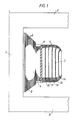
- Figure 1 shows part of a transformer core with leg 1 and upper and lower yoke 2 and 3. Concentrically around the leg 1, an inner winding 4 and an outer winding 5 are arranged.
- the windings consist of aluminum or copper foil 6 or 7 wound in many turns, the thickness of which can be between 0.01 and 3 mm. Between the turns is a film of suitable insulating material, for example polyethylene glycol terephthalate, the thickness of which can be, for example, between 0.01 and 0.1 mm.
- the inner winding 4 is wound on a winding cylinder 8, which is made, for example, of fiberglass-reinforced polyester or metallic material, such as Aluminum.
- the outer winding 5 is wound on the inner winding with an intermediate insulation gap in which ribs 9 made of pressboard, bakelite or glass fiber reinforced polyester are arranged parallel to the axis of the windings.
- the iron core of the transformer with the windings is in one with insulating liquid, e.g. Oil, filled transformer tank arranged.
- the windings are cooled in that the insulating liquid circulates through cooling channels in the windings, which are formed by cooling channel elements which are arranged between two adjacent turns of the conductor strip at different radial distances from the geometric axis of the windings. In Figure 1, only the cooling channel elements 10 to 14 are shown in the outer winding 5.
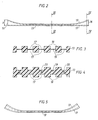
- FIGS 2 to 5 show the structure of the cooling duct element - 13.
- the remaining cooling duct elements in the outer winding are constructed in the same way.
- the cooling duct element 13 shown is produced from a rectangular, originally flat clamping chip with a thickness h of, for example, 8 mm, a width of, for example, 0.5 m and a length which has at least the width of the conductor foil, for example 2 m.
- One broad side of the press washer is worked on a profile, e.g. sawn that the disk gets a thickness increasing towards its two narrow sides 15, 16.
- Parallel grooves 17 are formed on both broad sides of the disk and form cooling channels.
- the grooves 17 on the two broad sides of the disk lie exactly opposite one another in pairs and extend from one narrow side 15, 16 of the disk to the other.
- the thicker edge regions of the elements are frayed by the provision of continuous grooves 20 at the ends of each second connecting piece 19. These edge areas are also softened by pushing them through softening rollers, after which they can easily assume the shape shown in FIG.
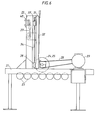
- FIGS. 6 and 7 schematically show a saw for sawing cooling duct elements of the type shown in FIGS. 2 to 5.
- the saw has a fixed stand with a horizontal stand part 21 and a vertical stand part 22 arranged thereon.
- the horizontal stand part 21 there are several Support rollers 23 are mounted, on which the insulating disks provided for the production of cooling duct elements are advanced during sawing.
- the saw is provided with a large number of sawblades 24, '25, have the two different diameters.
- the saw blades are fastened coaxially next to one another on a shaft 26, on which a pulley 27 is also seated, via which the shaft is driven by a motor 29 by means of a V-belt 28.
- the one of two diameters Saw blades are mounted alternately on the shaft 26, so that adjacent saw blades 24, 25 always have different diameters.
- the shaft 26 is mounted in a holder which is vertically displaceable on the vertical stand part 22.
- This holder comprises two vertical supports 30, 31 and a sheet 32 holding the supports together.
- Each support 30, 31 carries on one side one of the bearings for the shaft 26 with the saw blades.
- On its other side, each support is provided with a round shaft 33 or 34 which extends along the associated support and is fixedly attached to this support.
- These shafts are supported at their two ends in ball bushings 35, 36 and 37, 38, which are fixed to the vertical stand part 22.
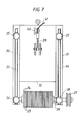
- the movable plate 32 is connected via a set screw 39 to a disk motor 40, which is controlled by connecting lines 41 by a processor in such a way that the height of the saw blades changes automatically in a predetermined manner depending on the position of the insulating material disk to be processed on the support rollers 23 becomes.
- a processor in which the shaft with the saw blades can be raised and lowered in the manner mentioned, the profile of the cooling duct elements can be changed as desired and adapted to the customer's requirements. This makes it possible to obtain the correct shape for a transformer winding with bent-out end sections in a relatively simple manner.
Landscapes
- Engineering & Computer Science (AREA)
- Power Engineering (AREA)
- Manufacturing & Machinery (AREA)
- Coils Of Transformers For General Uses (AREA)
- Insulating Of Coils (AREA)
- Transformer Cooling (AREA)
- Physical Or Chemical Processes And Apparatus (AREA)
- Infusion, Injection, And Reservoir Apparatuses (AREA)
- Coil Winding Methods And Apparatuses (AREA)
Abstract
Description
- Die Erfindung betrifft einen mit Isolierflüssigkeit gekühlten Transformator oder entsprechend gekühlte Drossel gemäß dem Oberbegriff des Anspruches 1, ein Herstellungsverfahren für den Transformator oder die Drossel und eine Anordnung zur Durchführung eines solchen Verfahrens.
- In Transformatoren und Drosseln mit Band- oder Foliewicklungen kann eine starke Stromverdrängung zu den Rändern des Bandes hin auftreten, die einerseits hohe Zusatzverluste und andererseits eine starke örtliche Erwärmung an den Rändern des Bandes verursacht. Durch die DE-OS 30 29 416 ist es bereits bekannt, die Stromverdrängung im Leiterband dadurch zu reduzieren, daß man das Band so formt, daß es in seinen Randbereichen einer doppeltgebogenen Fläche folgt. Dabei erzielt man das beste Resultat, wenn die Form des doppeltgebogenen Leiterbandes während des Wickelvorganges in bestimmter Weise variiert wird. Der radiale Abstand des Leiterbandes von der geometrischen Achse der Wicklung varriert bei solchen Wicklungen in achsialer Richtung und ist, zumindest für den radial äußeren Teil der Wicklung, an den achsialen Wicklungsenden am größten. Bei einer gleichmäßig dicken Metallfolie ist somit eine Ausfüllung erforderlich, um an den axialen Wicklungsenden die gewünschte trichterförmige Form zu erhalten. Es ist unter anderem aus dielektrischen Gründen wünschenswert, daß diese Ausfüllung aus elektrisch isolierendem Material besteht. Da ein solches Material eine schlechte Wärmeleitfähigkeit hat, muß die Ausfüllung in thermischen Symmetrieebenen liegen, d.h. entweder in der Mitte der Kühlkanäle oder in der Mitte zwischen zwei benachbarten Kühlkanälen, so daß die Wärmeleitung in radialer Richtung nicht behindert wird.
- Bei Wicklungen mit Kühlkanalelementen der an sich vorteilhaften Ausführung, die aus einer gleichmäßig dicken, biegsamen Isoliermaterialscheibe besteht, in der auf beiden Seiten Nuten für die Kühlflüssigkeitszirkulation eingearbeitet sind (Europäische Patentanmeldung 81 10 3568.2) ist es jedoch schwer, im Anschluß an die Kühlkanäle separate Füllmittel in der oben genannten Art anzubringen. Das Einlegen eines separaten Füllmittels verursacht ganz allgemein Probleme bei der Plazierung des Füllmittels, da die Lage des Füllmittels sehr präzise sein muß. Ein solches Einlegen erfordert einen hohen handwerklichen Aufwand, der zu hohen Herstellungskosten führt.
- Der Erfindung liegt die Aufgabe zugrunde, einen Transformator oder eine Drossel der eingangs genannten Art zu entwickeln, bei dem das aufgezeigte Problem bei der Anbringung von Füllmittel in den axialen Endbereichen der Wicklung in einfacher Weise gelöst ist.
- Zur Lösung dieser Aufgabe wird ein Transformator oder eine Drossel nach dem Oberbegriff des Anspruches 1 vorgeschlagen, der/die die im kennzeichnenden Teil des Anspruches 1 genannten Merkmale hat.
- Vorteilhafte Weiterbildungen des Transformators oder der Drossel sind in den Ansprüchen 2 und 3 genannt. Ein Verfahren zur Herstellung eines Transformators oder einer Drossel gemäß der Erfindung ist erfindungsgemäß durch die im Anspruch 4 genannten Merkmale gekennzeichnet.
- Eine Anordnung zur Durchführung dieses Verfahrens ist durch die in den Ansprüchen 5 und 6 genannten Merkmale gekennzeichnet.
- Die Erfindung beruht auf der Idee, das eingangs genannte Füllmittel in die Kühlkanalelemente zu integrieren.
- Das Kühlkanalelement wird vorzugsweise aus einer zunächst ebenen, rechteckigen Preßspannscheibe hergestellt, die auf ihrer einen Breitseite mit einem solchen Profil versehen wird, daß die Scheibe in den Bereichen längs zweier gegenüberliegender paralleler Schmalseiten eine in Richtung auf diese Schmalseiten zunehmende Dicke hat, die so bemessen ist, daß die Randabschnitte des Leiterbandes die gewünschte herausgebogene Form bekommen.
- Das Herstellen der Kühlkanalelemente erfolgt vorzugsweise mittels einer Sägemaschine, die mit mehreren Sägeblättern mit zwei verschiedenen Durchmessern arbeitet. Die Sägeblätter sind abwechselnd mit den beiden vorkommenden Durchmessern koaxial nebeneinander auf einer Welle angeordnet, die im Verhältnis zu einer Stützebene, auf der die Isoliermaterialscheiben für die Kühlkanalelemente vorgeschoben werden, gehoben und gesenkt werden kann. Die Höhenlage der Welle wird dabei in Abhängigkeit von der Lage der Isoliermaterialscheibe auf der Stützebene gesteuert. Diese Steuerung erfolgt vorzugsweisemit Hilfe eines Prozessors. Durch dieses Verfahren kann das Profil des Kühlkanalelementes beliebig geändert werden und allen gewünschten Formen angepaßt werden. Beim Wickeln der Wicklung braucht man dann nur die Reihenfolge der Kühlkanalelemente zu berücksichtigen um die gewünschte Form der Wicklung zu erhalten.
- Anhand der in den Figuren gezeigten Ausführungsbeispiele soll die Erfindung näher erläutert werden. Es zeigen
- Figur 1 schematisch einen Schnitt durch einen Teil eines Transformators gemäß der Erfindung,
- Figur 2 in Seitenansicht ein Ausführungsbeispiel eines Kühlkanalelementes für einen Transformator gemäß Figur 1,
- -Figur 3 einen Schnitt durch das Kühlkanalelement längs der Linie III - III in Figur 2,
- Figur 4 einen Schnitt durch das Kühlkanalelement längs der Linie IV - IV in Figur 2,
- Figur 5 in Seitenansicht das Kühlkanalelement nach Figur 2 nach dem Weichmachen seiner dickeren Randbereiche,
- Figur 6 schematisch in Seitenansicht eine Sägemaschine zum Sägen von Kühlkanalelementen nach Art der Figuren 2 bis 5,
- Figur 7 eine Vorderansicht des oberen Teils der Sägemaschine gemäß Figur 6.
- Figur 1 zeigt einen Teil eines Transformatorkerns mit Schenkel 1 sowie oberem und unterem Joch 2 bzw. 3. Konzentrisch um den Schenkel 1 sind eine Innenwicklung 4 und eine Außenwicklung 5 angeordnet. Die Wicklungen bestehen aus in vielen Windungen gewickelter Aluminium- oder Kupferfolie 6 bzw. 7, deren Dicke zwischen 0,01 und 3 mm liegen kann. Zwischen den Windungen liegt ein Film aus geeignetem Isoliermaterial, beispielsweise Polyäthylenglykolterephtalat, dessen Dicke beispielsweise zwischen 0,01 und 0,1 mm liegen kann. Die Innenwicklung 4 ist auf einen Wicklungszylinder 8 gewickelt, der beispielsweise aus glasfaserarmiertem Polyester oder metallischem Material, wie z.B. Aluminium,bestehen kann. Die Außenwicklung 5 ist auf die Innenwicklung mit einem zwischenliegenden Isolationsspalt gewickelt, in dem Rippen 9 aus Preßspan, Bakelit oder glasfaserarmiertem Polyester parallel zur Achse der Wicklungen angeordnet sind. Der Eisenkern des Transformators mit den Wicklungen ist in einem mit Isolierflüssigkeit, z.B. Öl, gefüllten Transformatorkessel angeordnet. Die Wicklungen werden dadurch gekühlt, daß die Isolierflüssigkeit durch Kühlkanäle in den Wicklungen zirkuliert, die von Kühlkanalelementen gebildet werden, welche zwischen je zwei benachbarten Windungen des Leiterbandes in verschiedenen radialen Abständen von der geometrischen Achse der Wicklungen angeordnet sind. In Figur 1 werden nur die Kühlkanalelemente 10 bis 14 in der Außenwicklung 5 gezeigt.
- Die Figuren 2 bis 5 zeigen den Aufbau des Kühlkanalelementes - 13. Die übrigen Kühlkanalelemente in der Außenwicklung sind in gleicher Weise aufgebaut. Das gezeigte Kühlkanalelement 13 ist hergestellt aus einer rechteckigen, ursprünglich ebenen Preßspanscheibe mit einer Dicke h von beispielsweise 8 mm, einer Breite von beispielsweise 0,5 m und einer Länge, die mindestens die Breite der Leiterfolie, beispielsweise 2 m, hat. Die eine Breitseite der Preßspanscheibe ist derart auf Profil gearbeitet, z.B. gesägt, daß die Scheibe eine nach ihren beiden Schmalseiten 15, 16 hin zunehmende Dicke bekommt. Auf beiden Breitseiten der Scheibe sind parallele Nuten 17 eingearbeitet, welche Kühlkanäle bilden. Die Nuten 17 auf den beiden Breitseiten der Scheibe liegen sich paarweise genau gegenüber und reichen von einer Schmalseite 15, 16 der Scheibe zur anderen. Das verbliebene Material an den Seiten der Nuten 17 bildet die Distanzelemente 18) während das verbliebene Material am Boden der Nuten die Verbindungsstücke 19 bildet. Um das Biegen der Kühlkanalelemente bei ihrer Anbringung in der Wicklung zu erleichtern, sind die dickeren Randbereiche der Elemente durch Anbringung von durchgehenden Nuten 20 an den Enden jedes zweiten Verbindungsstückes 19 aufgefranst. Diese Randbereiche werden außerdem dadurch weichgemacht, daß sie durch Weichmacherwalzen geschoben werden, wonach sie leicht die in Figur 5 gezeigte Form annehmen können.
- Die Figuren 6 und 7 zeigen schematisch eine Säge zum Sägen von Kühlkanalelementen der in den Figuren 2 bis 5 gezeigten Art. Die Säge hat ein festes Stativ mit einem horizontalen Stativteil 21 und 'einem hierauf angeordneten vertikalen Stativteil 22. In dem horizontalen Stativteil 21 sind mehrere Stützrollen 23 gelagert, auf welchen die für die Herstellung von Kühlkanalelementen vorgesehenen Isolierscheiben beim Sägen vorgeschoben werden. Die Säge ist mit einer großen Anzahl von Sägeblättern 24,'25 versehen, die zwei verschiedene Durchmesser haben. Die Sägeblätter sind koaxial nebeneinander auf einer Welle 26 befestigt, auf der auch eine Riemenscheibe 27 sitzt, über die die Welle mittels eines Keilriemens 28 von einem Motor 29 angetrieben wird. Die einen von zwei Durchmessern aufweisender Sägeblätter sind abwechselnd auf der Welle 26 angebracht, so daß benachbarte Sägeblätter 24, 25 stets verschiedene Durchmesser haben. Die Welle 26 ist in einem auf dem vertikalen Stativteil 22 vertikal verschiebbaren Halter gelagert. Dieser Halter umfaßt zwei vertikale Träger 30, 31 und ein die Träger zusammenhaltendes Blech 32. Jeder Träger 30, 31 trägt an seiner einen Seite eines der Lager für die Welle 26 mit den Sägeblättern. An seiner anderen Seite ist jeder Träger mit einer runden Welle 33 bzw. 34 versehen, die sich längs des zugehörigen Trägers erstreckt und an diesem Träger fest fixiert ist. Diese Wellen sind an ihren beiden Enden in Kugelbuchsen 35, 36 bzw. 37, 38 gelagert, die an dem vertikalen Stativteil 22 fest fixiert sind.
- Das bewegliche Blech 32 ist.über eine Stellschraube 39 mit einem Scheibenmotor 40 verbunden, der über Anschlußleitungen 41 durch einen Prozessor derart gesteuert wird, daß die Höhenlage der Sägeblätter in Abhängigkeit von der Lage der zu bearbeitenden Isoliermaterialscheibe auf den Stützrollen 23 automatisch auf vorbestimmte Weise geändert wird. Mit einer Säge, bei der die Welle mit den Sägeblättern in der,genannten Weise gehoben und gesenkt werden kann, kann das Profil der Kühlkanalelemente beliebig geändert und den Kundenwünschen angepaßt werden. Dadurch kann man auf verhältnismäßig einfache Weise die richtige Form für eine Transformatorwicklung mit herausgebogenen Endabschnitten erhalten.
Claims (5)
Applications Claiming Priority (2)
| Application Number | Priority Date | Filing Date | Title |
|---|---|---|---|
| SE8101197A SE428979B (sv) | 1981-02-24 | 1981-02-24 | Med isolervetska kyld transformator eller reaktor |
| SE8101197 | 1981-02-24 |
Publications (2)
| Publication Number | Publication Date |
|---|---|
| EP0058905A1 true EP0058905A1 (de) | 1982-09-01 |
| EP0058905B1 EP0058905B1 (de) | 1984-10-17 |
Family
ID=20343203
Family Applications (1)
| Application Number | Title | Priority Date | Filing Date |
|---|---|---|---|
| EP82101098A Expired EP0058905B1 (de) | 1981-02-24 | 1982-02-15 | Mit Isolierflüssigkeit gekühlter Transformator oder gekühlte Drossel nebst Herstellungsverfahren und Anordnung zur Durchführung des Verfahrens |
Country Status (8)
| Country | Link |
|---|---|
| US (1) | US4477790A (de) |
| EP (1) | EP0058905B1 (de) |
| JP (1) | JPS57155711A (de) |
| CA (1) | CA1182876A (de) |
| DE (1) | DE3260979D1 (de) |
| NO (1) | NO820539L (de) |
| SE (1) | SE428979B (de) |
| ZA (1) | ZA821169B (de) |
Cited By (1)
| Publication number | Priority date | Publication date | Assignee | Title |
|---|---|---|---|---|
| EP0538777A1 (de) * | 1991-10-23 | 1993-04-28 | Asea Brown Boveri Ab | Mit Isoliermittel gekühlter Transformator oder Drossel |
Families Citing this family (4)
| Publication number | Priority date | Publication date | Assignee | Title |
|---|---|---|---|---|
| US6103359A (en) * | 1996-05-22 | 2000-08-15 | Jsr Corporation | Process and apparatus for manufacturing an anisotropic conductor sheet and a magnetic mold piece for the same |
| US6163241A (en) * | 1999-08-31 | 2000-12-19 | Stupak, Jr.; Joseph J. | Coil and method for magnetizing an article |
| JP4728015B2 (ja) * | 2005-03-02 | 2011-07-20 | 鈴野化成株式会社 | 棒状化粧材繰出容器 |
| US9514878B2 (en) * | 2013-11-22 | 2016-12-06 | Tamura Corporation | Coil and manufacturing method for same, and reactor |
Citations (4)
| Publication number | Priority date | Publication date | Assignee | Title |
|---|---|---|---|---|
| DE1292745B (de) * | 1964-07-08 | 1969-04-17 | Comp Generale Electricite | Transformator oder Drosselspule grosser Leistung |
| DE2653315A1 (de) * | 1976-10-29 | 1978-05-03 | Bbc Brown Boveri & Cie | Isolations- und distanzierungskoerper zur axialen isolierung und distanzierung der leiter von spulen und verfahren zu dessen herstellung |
| DE2753055A1 (de) * | 1977-11-28 | 1979-05-31 | Siemens Ag | Verfahren zum aufbau einer supraleitenden magnetwicklung |
| FR2463492A1 (fr) * | 1979-08-14 | 1981-02-20 | Asea Ab | Transformateur ou bobine |
Family Cites Families (5)
| Publication number | Priority date | Publication date | Assignee | Title |
|---|---|---|---|---|
| US3056071A (en) * | 1959-02-12 | 1962-09-25 | William R Baker | Electrical coil structure |
| GB962222A (en) * | 1959-10-29 | 1964-07-01 | English Electric Co Ltd | Improvements in or relating to inductive windings |
| DE1948848A1 (de) * | 1969-09-26 | 1971-04-01 | Siemens Ag | Spulenwicklung |
| US3748616A (en) * | 1972-03-24 | 1973-07-24 | Ite Imperial Corp | Transformer winding structure using corrugated spacers |
| SE417466B (sv) * | 1978-11-09 | 1981-03-16 | Asea Ab | Krafttransformator |
-
1981
- 1981-02-24 SE SE8101197A patent/SE428979B/sv not_active IP Right Cessation
-
1982
- 1982-02-15 DE DE8282101098T patent/DE3260979D1/de not_active Expired
- 1982-02-15 EP EP82101098A patent/EP0058905B1/de not_active Expired
- 1982-02-22 US US06/351,255 patent/US4477790A/en not_active Expired - Fee Related
- 1982-02-22 NO NO820539A patent/NO820539L/no unknown
- 1982-02-23 ZA ZA821169A patent/ZA821169B/xx unknown
- 1982-02-23 CA CA000396879A patent/CA1182876A/en not_active Expired
- 1982-02-23 JP JP57028039A patent/JPS57155711A/ja active Pending
Patent Citations (4)
| Publication number | Priority date | Publication date | Assignee | Title |
|---|---|---|---|---|
| DE1292745B (de) * | 1964-07-08 | 1969-04-17 | Comp Generale Electricite | Transformator oder Drosselspule grosser Leistung |
| DE2653315A1 (de) * | 1976-10-29 | 1978-05-03 | Bbc Brown Boveri & Cie | Isolations- und distanzierungskoerper zur axialen isolierung und distanzierung der leiter von spulen und verfahren zu dessen herstellung |
| DE2753055A1 (de) * | 1977-11-28 | 1979-05-31 | Siemens Ag | Verfahren zum aufbau einer supraleitenden magnetwicklung |
| FR2463492A1 (fr) * | 1979-08-14 | 1981-02-20 | Asea Ab | Transformateur ou bobine |
Cited By (1)
| Publication number | Priority date | Publication date | Assignee | Title |
|---|---|---|---|---|
| EP0538777A1 (de) * | 1991-10-23 | 1993-04-28 | Asea Brown Boveri Ab | Mit Isoliermittel gekühlter Transformator oder Drossel |
Also Published As
| Publication number | Publication date |
|---|---|
| DE3260979D1 (en) | 1984-11-22 |
| ZA821169B (en) | 1983-01-26 |
| JPS57155711A (en) | 1982-09-25 |
| NO820539L (no) | 1982-08-25 |
| CA1182876A (en) | 1985-02-19 |
| SE428979B (sv) | 1983-08-01 |
| EP0058905B1 (de) | 1984-10-17 |
| US4477790A (en) | 1984-10-16 |
| SE8101197L (sv) | 1982-08-25 |
Similar Documents
| Publication | Publication Date | Title |
|---|---|---|
| DE3305007C2 (de) | ||
| DE1294541B (de) | Drossel ohne Eisenkern | |
| DE3518882C2 (de) | ||
| DE2847983A1 (de) | Induktive heizanlage | |
| EP0058905B1 (de) | Mit Isolierflüssigkeit gekühlter Transformator oder gekühlte Drossel nebst Herstellungsverfahren und Anordnung zur Durchführung des Verfahrens | |
| DE1921862A1 (de) | Isolations-Scheibenelement zur Abstuetzung von Scheibenspulen | |
| EP0040382B1 (de) | Bandwicklung für einen flüssigkeitsisolierten Transformator | |
| DE2441371C2 (de) | Vorrichtung zum Vernetzen einer mit Polyolefin isolierten Kabelseele | |
| DE2947801A1 (de) | Transformator oder drosselspule mit mindestens einer eine bandspule enthaltenden wicklung | |
| CH416817A (de) | Magnetkern, insbesondere für Transformatoren oder Drosseln | |
| EP0045035A1 (de) | Vorrichtung zum Schichten von Kernen für Transformatoren und Drosselspulen | |
| DE3413359C2 (de) | ||
| DE4136176A1 (de) | Toroiddrossel | |
| WO2008125288A1 (de) | Elektrisches bauteil mit wicklung und anzapfung | |
| EP0012739B1 (de) | Drosselspule | |
| DE2836283C2 (de) | Elektrische Gerätewicklung | |
| EP0014418B2 (de) | Wicklung für einen luftgekühlten Trockentransformator | |
| DE1563479C2 (de) | Wicklung fur flussigkeitsgekuhlte Transformatoren, Drosselspulen, Wandler oder Transduktoren | |
| DE4226764A1 (de) | Drosselspule | |
| DE3533323C2 (de) | ||
| DE3105356A1 (de) | Radialgeblechter eisenkern fuer drosselspulen | |
| DE3141972A1 (de) | Eisenkern fuer elektrische drosseln | |
| EP0166952B1 (de) | Hochstromtransformator mit indirekter Spannungseinstellung über einen Zwischenkreis | |
| DE2753952A1 (de) | Anordnung zum aufnehmen von kurzschlusskraeften in strakstromtransformatoren | |
| DE1060556B (de) | Elektrische Ruehrwicklung |
Legal Events
| Date | Code | Title | Description |
|---|---|---|---|
| PUAI | Public reference made under article 153(3) epc to a published international application that has entered the european phase |
Free format text: ORIGINAL CODE: 0009012 |
|
| AK | Designated contracting states |
Designated state(s): BE CH DE FR GB |
|
| 17P | Request for examination filed |
Effective date: 19830113 |
|
| GRAA | (expected) grant |
Free format text: ORIGINAL CODE: 0009210 |
|
| AK | Designated contracting states |
Designated state(s): BE CH DE FR GB LI |
|
| REF | Corresponds to: |
Ref document number: 3260979 Country of ref document: DE Date of ref document: 19841122 |
|
| PGFP | Annual fee paid to national office [announced via postgrant information from national office to epo] |
Ref country code: FR Payment date: 19841220 Year of fee payment: 4 |
|
| PGFP | Annual fee paid to national office [announced via postgrant information from national office to epo] |
Ref country code: BE Payment date: 19841231 Year of fee payment: 4 |
|
| ET | Fr: translation filed | ||
| PGFP | Annual fee paid to national office [announced via postgrant information from national office to epo] |
Ref country code: DE Payment date: 19850225 Year of fee payment: 4 |
|
| PLBE | No opposition filed within time limit |
Free format text: ORIGINAL CODE: 0009261 |
|
| 26N | No opposition filed | ||
| PG25 | Lapsed in a contracting state [announced via postgrant information from national office to epo] |
Ref country code: LI Effective date: 19870228 Ref country code: CH Effective date: 19870228 |
|
| BERE | Be: lapsed |
Owner name: ASEA A.B. Effective date: 19870228 |
|
| GBPC | Gb: european patent ceased through non-payment of renewal fee | ||
| PG25 | Lapsed in a contracting state [announced via postgrant information from national office to epo] |
Ref country code: FR Free format text: LAPSE BECAUSE OF NON-PAYMENT OF DUE FEES Effective date: 19871030 |
|
| REG | Reference to a national code |
Ref country code: CH Ref legal event code: PL |
|
| PG25 | Lapsed in a contracting state [announced via postgrant information from national office to epo] |
Ref country code: DE Effective date: 19871103 |
|
| REG | Reference to a national code |
Ref country code: FR Ref legal event code: ST |
|
| PG25 | Lapsed in a contracting state [announced via postgrant information from national office to epo] |
Ref country code: GB Effective date: 19881121 |
|
| PG25 | Lapsed in a contracting state [announced via postgrant information from national office to epo] |
Ref country code: BE Effective date: 19890228 |