EP0058905A1 - Transformateur ou inductance refroidi par liquide isolant, procédé et dispositif de fabrication - Google Patents
Transformateur ou inductance refroidi par liquide isolant, procédé et dispositif de fabrication Download PDFInfo
- Publication number
- EP0058905A1 EP0058905A1 EP82101098A EP82101098A EP0058905A1 EP 0058905 A1 EP0058905 A1 EP 0058905A1 EP 82101098 A EP82101098 A EP 82101098A EP 82101098 A EP82101098 A EP 82101098A EP 0058905 A1 EP0058905 A1 EP 0058905A1
- Authority
- EP
- European Patent Office
- Prior art keywords
- winding
- transformer
- windings
- band
- shaft
- Prior art date
- Legal status (The legal status is an assumption and is not a legal conclusion. Google has not performed a legal analysis and makes no representation as to the accuracy of the status listed.)
- Granted
Links
Images
Classifications
-
- H—ELECTRICITY
- H01—ELECTRIC ELEMENTS
- H01F—MAGNETS; INDUCTANCES; TRANSFORMERS; SELECTION OF MATERIALS FOR THEIR MAGNETIC PROPERTIES
- H01F41/00—Apparatus or processes specially adapted for manufacturing or assembling magnets, inductances or transformers; Apparatus or processes specially adapted for manufacturing materials characterised by their magnetic properties
- H01F41/02—Apparatus or processes specially adapted for manufacturing or assembling magnets, inductances or transformers; Apparatus or processes specially adapted for manufacturing materials characterised by their magnetic properties for manufacturing cores, coils, or magnets
- H01F41/04—Apparatus or processes specially adapted for manufacturing or assembling magnets, inductances or transformers; Apparatus or processes specially adapted for manufacturing materials characterised by their magnetic properties for manufacturing cores, coils, or magnets for manufacturing coils
- H01F41/12—Insulating of windings
- H01F41/125—Other insulating structures; Insulating between coil and core, between different winding sections, around the coil
-
- H—ELECTRICITY
- H01—ELECTRIC ELEMENTS
- H01F—MAGNETS; INDUCTANCES; TRANSFORMERS; SELECTION OF MATERIALS FOR THEIR MAGNETIC PROPERTIES
- H01F27/00—Details of transformers or inductances, in general
- H01F27/28—Coils; Windings; Conductive connections
- H01F27/32—Insulating of coils, windings, or parts thereof
- H01F27/322—Insulating of coils, windings, or parts thereof the insulation forming channels for circulation of the fluid
-
- Y—GENERAL TAGGING OF NEW TECHNOLOGICAL DEVELOPMENTS; GENERAL TAGGING OF CROSS-SECTIONAL TECHNOLOGIES SPANNING OVER SEVERAL SECTIONS OF THE IPC; TECHNICAL SUBJECTS COVERED BY FORMER USPC CROSS-REFERENCE ART COLLECTIONS [XRACs] AND DIGESTS
- Y10—TECHNICAL SUBJECTS COVERED BY FORMER USPC
- Y10T—TECHNICAL SUBJECTS COVERED BY FORMER US CLASSIFICATION
- Y10T29/00—Metal working
- Y10T29/49—Method of mechanical manufacture
- Y10T29/49002—Electrical device making
- Y10T29/4902—Electromagnet, transformer or inductor
Definitions
- the invention relates to a transformer cooled with insulating liquid or a correspondingly cooled choke according to the preamble of claim 1, a manufacturing method for the transformer or the choke and an arrangement for carrying out such a method.
- filling is required in order to obtain the desired funnel-shaped shape at the axial winding ends. It is desirable, among other things, for dielectric reasons that this filling is made of an electrically insulating material. There such a material has poor thermal conductivity, the filling must lie in thermal planes of symmetry, ie either in the middle of the cooling channels or in the middle between two adjacent cooling channels, so that heat conduction in the radial direction is not hindered.
- the invention has for its object to develop a transformer or a choke of the type mentioned, in which the problem shown in the application of filler in the axial end regions of the winding is solved in a simple manner.
- the invention is based on the idea of integrating the filler mentioned at the outset into the cooling channel elements.
- the cooling duct element is preferably made from an initially flat, rectangular compression washer, which is provided on one broad side with such a profile that the washer in the areas along two opposite parallel narrow sides has an increasing thickness towards these narrow sides, which is so dimensioned that the edge sections of the conductor strip get the desired bent shape.
- the cooling duct elements are preferably produced by means of a sawing machine which works with a plurality of saw blades with two different diameters.
- the saw blades are arranged alternately with the two existing diameters coaxially next to one another on a shaft which can be raised and lowered in relation to a support plane on which the insulating material disks for the cooling channel elements are advanced.
- the height of the shaft is controlled depending on the position of the insulating material disc on the support plane. This control is preferably carried out using a processor.
- the profile of the cooling channel element can be changed as desired and can be adapted to all desired shapes. When winding the winding, one only needs to take into account the sequence of the cooling channel elements in order to obtain the desired shape of the winding.
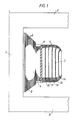
- Figure 1 shows part of a transformer core with leg 1 and upper and lower yoke 2 and 3. Concentrically around the leg 1, an inner winding 4 and an outer winding 5 are arranged.
- the windings consist of aluminum or copper foil 6 or 7 wound in many turns, the thickness of which can be between 0.01 and 3 mm. Between the turns is a film of suitable insulating material, for example polyethylene glycol terephthalate, the thickness of which can be, for example, between 0.01 and 0.1 mm.
- the inner winding 4 is wound on a winding cylinder 8, which is made, for example, of fiberglass-reinforced polyester or metallic material, such as Aluminum.
- the outer winding 5 is wound on the inner winding with an intermediate insulation gap in which ribs 9 made of pressboard, bakelite or glass fiber reinforced polyester are arranged parallel to the axis of the windings.
- the iron core of the transformer with the windings is in one with insulating liquid, e.g. Oil, filled transformer tank arranged.
- the windings are cooled in that the insulating liquid circulates through cooling channels in the windings, which are formed by cooling channel elements which are arranged between two adjacent turns of the conductor strip at different radial distances from the geometric axis of the windings. In Figure 1, only the cooling channel elements 10 to 14 are shown in the outer winding 5.
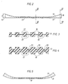
- FIGS 2 to 5 show the structure of the cooling duct element - 13.
- the remaining cooling duct elements in the outer winding are constructed in the same way.
- the cooling duct element 13 shown is produced from a rectangular, originally flat clamping chip with a thickness h of, for example, 8 mm, a width of, for example, 0.5 m and a length which has at least the width of the conductor foil, for example 2 m.
- One broad side of the press washer is worked on a profile, e.g. sawn that the disk gets a thickness increasing towards its two narrow sides 15, 16.
- Parallel grooves 17 are formed on both broad sides of the disk and form cooling channels.
- the grooves 17 on the two broad sides of the disk lie exactly opposite one another in pairs and extend from one narrow side 15, 16 of the disk to the other.
- the thicker edge regions of the elements are frayed by the provision of continuous grooves 20 at the ends of each second connecting piece 19. These edge areas are also softened by pushing them through softening rollers, after which they can easily assume the shape shown in FIG.
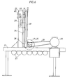
- FIGS. 6 and 7 schematically show a saw for sawing cooling duct elements of the type shown in FIGS. 2 to 5.
- the saw has a fixed stand with a horizontal stand part 21 and a vertical stand part 22 arranged thereon.
- the horizontal stand part 21 there are several Support rollers 23 are mounted, on which the insulating disks provided for the production of cooling duct elements are advanced during sawing.
- the saw is provided with a large number of sawblades 24, '25, have the two different diameters.
- the saw blades are fastened coaxially next to one another on a shaft 26, on which a pulley 27 is also seated, via which the shaft is driven by a motor 29 by means of a V-belt 28.
- the one of two diameters Saw blades are mounted alternately on the shaft 26, so that adjacent saw blades 24, 25 always have different diameters.
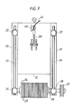
- the shaft 26 is mounted in a holder which is vertically displaceable on the vertical stand part 22.
- This holder comprises two vertical supports 30, 31 and a sheet 32 holding the supports together.
- Each support 30, 31 carries on one side one of the bearings for the shaft 26 with the saw blades.
- On its other side, each support is provided with a round shaft 33 or 34 which extends along the associated support and is fixedly attached to this support.
- These shafts are supported at their two ends in ball bushings 35, 36 and 37, 38, which are fixed to the vertical stand part 22.
- the movable plate 32 is connected via a set screw 39 to a disk motor 40, which is controlled by connecting lines 41 by a processor in such a way that the height of the saw blades changes automatically in a predetermined manner depending on the position of the insulating material disk to be processed on the support rollers 23 becomes.
- a processor in which the shaft with the saw blades can be raised and lowered in the manner mentioned, the profile of the cooling duct elements can be changed as desired and adapted to the customer's requirements. This makes it possible to obtain the correct shape for a transformer winding with bent-out end sections in a relatively simple manner.
Landscapes
- Engineering & Computer Science (AREA)
- Power Engineering (AREA)
- Manufacturing & Machinery (AREA)
- Coils Of Transformers For General Uses (AREA)
- Insulating Of Coils (AREA)
- Transformer Cooling (AREA)
- Infusion, Injection, And Reservoir Apparatuses (AREA)
- Physical Or Chemical Processes And Apparatus (AREA)
- Coil Winding Methods And Apparatuses (AREA)
Applications Claiming Priority (2)
| Application Number | Priority Date | Filing Date | Title |
|---|---|---|---|
| SE8101197A SE428979B (sv) | 1981-02-24 | 1981-02-24 | Med isolervetska kyld transformator eller reaktor |
| SE8101197 | 1981-02-24 |
Publications (2)
| Publication Number | Publication Date |
|---|---|
| EP0058905A1 true EP0058905A1 (fr) | 1982-09-01 |
| EP0058905B1 EP0058905B1 (fr) | 1984-10-17 |
Family
ID=20343203
Family Applications (1)
| Application Number | Title | Priority Date | Filing Date |
|---|---|---|---|
| EP82101098A Expired EP0058905B1 (fr) | 1981-02-24 | 1982-02-15 | Transformateur ou inductance refroidi par liquide isolant, procédé et dispositif de fabrication |
Country Status (8)
| Country | Link |
|---|---|
| US (1) | US4477790A (fr) |
| EP (1) | EP0058905B1 (fr) |
| JP (1) | JPS57155711A (fr) |
| CA (1) | CA1182876A (fr) |
| DE (1) | DE3260979D1 (fr) |
| NO (1) | NO820539L (fr) |
| SE (1) | SE428979B (fr) |
| ZA (1) | ZA821169B (fr) |
Cited By (1)
| Publication number | Priority date | Publication date | Assignee | Title |
|---|---|---|---|---|
| EP0538777A1 (fr) * | 1991-10-23 | 1993-04-28 | Asea Brown Boveri Ab | Transformateur ou réactance refroidis par un agent isolant |
Families Citing this family (4)
| Publication number | Priority date | Publication date | Assignee | Title |
|---|---|---|---|---|
| US6103359A (en) * | 1996-05-22 | 2000-08-15 | Jsr Corporation | Process and apparatus for manufacturing an anisotropic conductor sheet and a magnetic mold piece for the same |
| US6163241A (en) * | 1999-08-31 | 2000-12-19 | Stupak, Jr.; Joseph J. | Coil and method for magnetizing an article |
| JP4728015B2 (ja) * | 2005-03-02 | 2011-07-20 | 鈴野化成株式会社 | 棒状化粧材繰出容器 |
| US9514878B2 (en) * | 2013-11-22 | 2016-12-06 | Tamura Corporation | Coil and manufacturing method for same, and reactor |
Citations (4)
| Publication number | Priority date | Publication date | Assignee | Title |
|---|---|---|---|---|
| DE1292745B (de) * | 1964-07-08 | 1969-04-17 | Comp Generale Electricite | Transformator oder Drosselspule grosser Leistung |
| DE2653315A1 (de) * | 1976-10-29 | 1978-05-03 | Bbc Brown Boveri & Cie | Isolations- und distanzierungskoerper zur axialen isolierung und distanzierung der leiter von spulen und verfahren zu dessen herstellung |
| DE2753055A1 (de) * | 1977-11-28 | 1979-05-31 | Siemens Ag | Verfahren zum aufbau einer supraleitenden magnetwicklung |
| FR2463492A1 (fr) * | 1979-08-14 | 1981-02-20 | Asea Ab | Transformateur ou bobine |
Family Cites Families (5)
| Publication number | Priority date | Publication date | Assignee | Title |
|---|---|---|---|---|
| US3056071A (en) * | 1959-02-12 | 1962-09-25 | William R Baker | Electrical coil structure |
| GB962222A (en) * | 1959-10-29 | 1964-07-01 | English Electric Co Ltd | Improvements in or relating to inductive windings |
| DE1948848A1 (de) * | 1969-09-26 | 1971-04-01 | Siemens Ag | Spulenwicklung |
| US3748616A (en) * | 1972-03-24 | 1973-07-24 | Ite Imperial Corp | Transformer winding structure using corrugated spacers |
| SE417466B (sv) * | 1978-11-09 | 1981-03-16 | Asea Ab | Krafttransformator |
-
1981
- 1981-02-24 SE SE8101197A patent/SE428979B/sv not_active IP Right Cessation
-
1982
- 1982-02-15 DE DE8282101098T patent/DE3260979D1/de not_active Expired
- 1982-02-15 EP EP82101098A patent/EP0058905B1/fr not_active Expired
- 1982-02-22 US US06/351,255 patent/US4477790A/en not_active Expired - Fee Related
- 1982-02-22 NO NO820539A patent/NO820539L/no unknown
- 1982-02-23 CA CA000396879A patent/CA1182876A/fr not_active Expired
- 1982-02-23 ZA ZA821169A patent/ZA821169B/xx unknown
- 1982-02-23 JP JP57028039A patent/JPS57155711A/ja active Pending
Patent Citations (4)
| Publication number | Priority date | Publication date | Assignee | Title |
|---|---|---|---|---|
| DE1292745B (de) * | 1964-07-08 | 1969-04-17 | Comp Generale Electricite | Transformator oder Drosselspule grosser Leistung |
| DE2653315A1 (de) * | 1976-10-29 | 1978-05-03 | Bbc Brown Boveri & Cie | Isolations- und distanzierungskoerper zur axialen isolierung und distanzierung der leiter von spulen und verfahren zu dessen herstellung |
| DE2753055A1 (de) * | 1977-11-28 | 1979-05-31 | Siemens Ag | Verfahren zum aufbau einer supraleitenden magnetwicklung |
| FR2463492A1 (fr) * | 1979-08-14 | 1981-02-20 | Asea Ab | Transformateur ou bobine |
Cited By (1)
| Publication number | Priority date | Publication date | Assignee | Title |
|---|---|---|---|---|
| EP0538777A1 (fr) * | 1991-10-23 | 1993-04-28 | Asea Brown Boveri Ab | Transformateur ou réactance refroidis par un agent isolant |
Also Published As
| Publication number | Publication date |
|---|---|
| DE3260979D1 (en) | 1984-11-22 |
| EP0058905B1 (fr) | 1984-10-17 |
| SE8101197L (sv) | 1982-08-25 |
| SE428979B (sv) | 1983-08-01 |
| ZA821169B (en) | 1983-01-26 |
| CA1182876A (fr) | 1985-02-19 |
| US4477790A (en) | 1984-10-16 |
| JPS57155711A (en) | 1982-09-25 |
| NO820539L (no) | 1982-08-25 |
Similar Documents
| Publication | Publication Date | Title |
|---|---|---|
| DE3305007C2 (fr) | ||
| EP0030338B1 (fr) | Conducteur électrique isolé pour enroulements de transformateurs et de bobines de self | |
| EP0058905B1 (fr) | Transformateur ou inductance refroidi par liquide isolant, procédé et dispositif de fabrication | |
| DE1921862A1 (de) | Isolations-Scheibenelement zur Abstuetzung von Scheibenspulen | |
| EP0040382B1 (fr) | Enroulement à conducteur en bande pour transformateur à liquide isolant | |
| DE2947801A1 (de) | Transformator oder drosselspule mit mindestens einer eine bandspule enthaltenden wicklung | |
| CH416817A (de) | Magnetkern, insbesondere für Transformatoren oder Drosseln | |
| EP0045035A1 (fr) | Dispositif d'assemblage de noyaux pour transformateurs et inductances | |
| DE3413359C2 (fr) | ||
| DE4136176A1 (de) | Toroiddrossel | |
| WO2008125288A1 (fr) | Composant électrique à enroulement et branchement | |
| EP0012739B1 (fr) | Bobine d'inductance | |
| EP0014418B2 (fr) | Enroulement pour un transformateur à sec refroidi par air | |
| DE1563479C2 (de) | Wicklung fur flussigkeitsgekuhlte Transformatoren, Drosselspulen, Wandler oder Transduktoren | |
| DE3533323C2 (fr) | ||
| CH668859A5 (de) | Verfahren zur herstellung eines streuflussfuehrungspaketes fuer transformatoren und drosselspulen. | |
| DE3105356A1 (de) | Radialgeblechter eisenkern fuer drosselspulen | |
| DE3141972A1 (de) | Eisenkern fuer elektrische drosseln | |
| EP0583644A1 (fr) | Inductance | |
| EP0166952B1 (fr) | Transformateur à forte intensité avec ajustement indirect de tension par circuit intermédiaire | |
| DE2753952A1 (de) | Anordnung zum aufnehmen von kurzschlusskraeften in strakstromtransformatoren | |
| DE1060556B (de) | Elektrische Ruehrwicklung | |
| DE3046505A1 (de) | Saugdrossel fuer hochstromtransformatoren | |
| DE3138402C2 (de) | Supraleitender Magnet und Vorrichtung zum Herstellen desselben | |
| DE3233308C2 (fr) |
Legal Events
| Date | Code | Title | Description |
|---|---|---|---|
| PUAI | Public reference made under article 153(3) epc to a published international application that has entered the european phase |
Free format text: ORIGINAL CODE: 0009012 |
|
| AK | Designated contracting states |
Designated state(s): BE CH DE FR GB |
|
| 17P | Request for examination filed |
Effective date: 19830113 |
|
| GRAA | (expected) grant |
Free format text: ORIGINAL CODE: 0009210 |
|
| AK | Designated contracting states |
Designated state(s): BE CH DE FR GB LI |
|
| REF | Corresponds to: |
Ref document number: 3260979 Country of ref document: DE Date of ref document: 19841122 |
|
| PGFP | Annual fee paid to national office [announced via postgrant information from national office to epo] |
Ref country code: FR Payment date: 19841220 Year of fee payment: 4 |
|
| PGFP | Annual fee paid to national office [announced via postgrant information from national office to epo] |
Ref country code: BE Payment date: 19841231 Year of fee payment: 4 |
|
| ET | Fr: translation filed | ||
| PGFP | Annual fee paid to national office [announced via postgrant information from national office to epo] |
Ref country code: DE Payment date: 19850225 Year of fee payment: 4 |
|
| PLBE | No opposition filed within time limit |
Free format text: ORIGINAL CODE: 0009261 |
|
| 26N | No opposition filed | ||
| PG25 | Lapsed in a contracting state [announced via postgrant information from national office to epo] |
Ref country code: LI Effective date: 19870228 Ref country code: CH Effective date: 19870228 |
|
| BERE | Be: lapsed |
Owner name: ASEA A.B. Effective date: 19870228 |
|
| GBPC | Gb: european patent ceased through non-payment of renewal fee | ||
| PG25 | Lapsed in a contracting state [announced via postgrant information from national office to epo] |
Ref country code: FR Free format text: LAPSE BECAUSE OF NON-PAYMENT OF DUE FEES Effective date: 19871030 |
|
| REG | Reference to a national code |
Ref country code: CH Ref legal event code: PL |
|
| PG25 | Lapsed in a contracting state [announced via postgrant information from national office to epo] |
Ref country code: DE Effective date: 19871103 |
|
| REG | Reference to a national code |
Ref country code: FR Ref legal event code: ST |
|
| PG25 | Lapsed in a contracting state [announced via postgrant information from national office to epo] |
Ref country code: GB Effective date: 19881121 |
|
| PG25 | Lapsed in a contracting state [announced via postgrant information from national office to epo] |
Ref country code: BE Effective date: 19890228 |