EP0056823A1 - Procede de commande de transfert pas a pas d'un support d'information - Google Patents
Procede de commande de transfert pas a pas d'un support d'information Download PDFInfo
- Publication number
- EP0056823A1 EP0056823A1 EP81902246A EP81902246A EP0056823A1 EP 0056823 A1 EP0056823 A1 EP 0056823A1 EP 81902246 A EP81902246 A EP 81902246A EP 81902246 A EP81902246 A EP 81902246A EP 0056823 A1 EP0056823 A1 EP 0056823A1
- Authority
- EP
- European Patent Office
- Prior art keywords
- recording
- data
- magnetic tape
- feed
- information medium
- Prior art date
- Legal status (The legal status is an assumption and is not a legal conclusion. Google has not performed a legal analysis and makes no representation as to the accuracy of the status listed.)
- Granted
Links
Images


Classifications
-
- G—PHYSICS
- G11—INFORMATION STORAGE
- G11B—INFORMATION STORAGE BASED ON RELATIVE MOVEMENT BETWEEN RECORD CARRIER AND TRANSDUCER
- G11B15/00—Driving, starting or stopping record carriers of filamentary or web form; Driving both such record carriers and heads; Guiding such record carriers or containers therefor; Control thereof; Control of operating function
- G11B15/60—Guiding record carrier
- G11B15/602—Guiding record carrier for track selection, acquisition or following
-
- G—PHYSICS
- G11—INFORMATION STORAGE
- G11B—INFORMATION STORAGE BASED ON RELATIVE MOVEMENT BETWEEN RECORD CARRIER AND TRANSDUCER
- G11B15/00—Driving, starting or stopping record carriers of filamentary or web form; Driving both such record carriers and heads; Guiding such record carriers or containers therefor; Control thereof; Control of operating function
- G11B15/02—Control of operating function, e.g. switching from recording to reproducing
-
- G—PHYSICS
- G11—INFORMATION STORAGE
- G11B—INFORMATION STORAGE BASED ON RELATIVE MOVEMENT BETWEEN RECORD CARRIER AND TRANSDUCER
- G11B15/00—Driving, starting or stopping record carriers of filamentary or web form; Driving both such record carriers and heads; Guiding such record carriers or containers therefor; Control thereof; Control of operating function
- G11B15/18—Driving; Starting; Stopping; Arrangements for control or regulation thereof
- G11B15/1808—Driving of both record carrier and head
-
- G—PHYSICS
- G11—INFORMATION STORAGE
- G11B—INFORMATION STORAGE BASED ON RELATIVE MOVEMENT BETWEEN RECORD CARRIER AND TRANSDUCER
- G11B20/00—Signal processing not specific to the method of recording or reproducing; Circuits therefor
- G11B20/10—Digital recording or reproducing
- G11B20/18—Error detection or correction; Testing, e.g. of drop-outs
- G11B20/1816—Testing
Definitions
- the present invention relates to a method for controlling the stepping feed of an information medium such as a magnetic tape used in a mass storage system (which is called an MSS).
- an information medium such as a magnetic tape used in a mass storage system (which is called an MSS).
- the information medium used in the MSS is called a data cartridge which is comprised of a magnetic tape approximately 7 cm wide and 20 m long housed in a cylindrical shell approximately 5.cm in diameter and 9 cm long.
- the data cartridge storage capacity is, for example, 50 M bytes and in addition, 706 to 9440 data cartridges can be stored in one MSS.
- Recording tracks on the magnetic tape are stripes which run diagonally across the tape and track positioning of a magnetic head is performed randomly by a servo mechanism.
- the present invention relates to a method for controlling. the stepping feed of such a magnetic tape by the amount of one stripe.
- One conventional method for controlling the stepping feed of a magnetic tape comprises the steps of: recording or reading data on a recording track; checking the recorded or read data on said recording track; feeding said magnetic tape by the amount of one stripe so as to record or read data on the next recording track, if no error is detected as a result of said checking; and recording or reading the . data again on said recording track, if an error is detected as a result of said checking.
- this conventional method since the feed operation of the magnetic tape cannot be started until the checking of recorded or read data is completed, it substantially takes a long time to feed the magnetic tape; in other words, there is a disadvantage in that the read speed for data is slow.
- a method for controlling the stepping feed of an information medium on which recording tracks are formed by stripes which run diagonally or vertically across said information medium comprising the steps of: recording or reading data on a first recording track; checking the recorded or read data on said first recording traz:k; feeding said information medium so as to record or read data on a second recording track next to said first recording track, after'said recording or reading is completed and before said checking is completed; and determining whether said feeding is to be forwarded or reversed in accordance with the result of said checking at a time when said checking is completed.
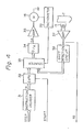
- Fig. 1 which illustrates a general mass storage system
- 1 is a cartridge store which has a large number of honeycomb-shaped cells 2.
- 3 is an accessor for taking one data cartridge out of the cartridge store 1 or putting one data cartridge into the cartridge store 1, which has a picker 4 for picking up a cartridge 5.
- the picker 4 is mounted on the accessor 3 so as to move along the X-, Y- and 8- directions indicated by arrows X, Y and 8, respectively.
- 6 is a data recording unit which has a spool motor 7, a guide 8, a vacuum column 9, a guide 10, a mandrel 11, a guide 12 and a take-up ' spoor 13.
- a magnetic head 14, which is rotated by a motor 15, is mounted on the mandrel 11. Further, the take-up spoor 13 is rotated by a stepping motor 16.
- the loading operation of a magnetic tape T stored in the data cartridge 5 in the data recording device 6 will be explained.
- the cartridge is automatically mounted on the axis of the spool motor 7..
- the cartridge is indicated by reference 5'.
- the magnetic tape T in the cartridge 5' is automatically wound on the data recording device 6 by a so-called auto-thread method. That is, the magnetic tape T of the cartridge 5' is supplied by the rotation of the spool motor 7 and, after that, the magnetic tape T moves along the guide 8, the guide 10, the mandrel 11 and the guide 12 to the take-up spool 13. As a result, the edge of the magnetic tape T is wound on the take-up spool 13.
- the vacuum column 9 is exhausted so as to be in a negative pressure state.
- the magnetic tape T is taken into the vacuum column 9. That is; the vacuum column 9 serves as a buffer which prevents large tension from abruptly being applied to the magnetic tape T.
- the magnetic tape T is helically wound on the mandrel 11, and that the recording or reading operation of data is performed upon the stationary magnetic tape T by the magnetic head 14 which diagonally scans the magnetic tape T.
- Fig. 2 is a diagram illustrating a data format of the magnetic tape T of Fig. 1.
- recording tracks are formed by stripes which run diagonally across the magnetic tape T.
- a recording track T is a scanning area on which the recording or reading operation is performed by one passage of the magnetic head 14 of Fig. 1.
- 20 is an ID area on which reference numbers and the like with respect to the recording tracks (stripes) are recorded . in advance; and 21-1, 21-2, 21-3 and 21-4 are servo areas on which servo information is recorded so as to make the magnetic head pass through the center of each stripe; 22 is a data area on which, for example, 4096 byte data per one stripe can be recorded.
- the magnetic head 14 of Fig. 1 scans the magnetic tape T along the direction as indicated by an arrow A.
- signals Sand S whose amplitudes are dependent on the penetration of the magnetic head into the servo area, are read.
- the core width of the magnetic head is equal to the length P 1 P 2 of a diagonal at an intersection between the scanning area (recording track) T n and the servo area 21-i, the above-mentioned read signals have triangular wave shaped envelopes.
- the scanning area T n forms a proper scanning locus
- the read signal S obtained at the above-mentioned intersection has a frequency which is twice those of the other read signals S.
- the shift quantity is fedback to the stepping motor 16 (Fig. 1) so as to control the feed of the magnetic tape T.
- the scanning locus of the magnetic head 14 (Fig. 1) can be corrected.
- Fig. 4 is a block circuit diagram of a stepping feed control circuit for carrying out the conventional method for controlling the stepping feed of an information medium.
- 31 is an instruction decoder which receives an instruction STEP from an upper unit (not shown) and generates a stepping feed quantity M corresponding to one strip;
- 32 is a gate circuit for passing the stepping feed quantity M from the instruction decoder 31 when receiving a ' start pulse signal START;
- 33 is a counter;
- 34 is a D/A converter for converting a digital output of the counter 33 into an analog voltage;
- 35 is a driving amplifier for amplifying the output of the D/A converter 34 and driving the take-up motor 16;
- 36 is a tachometer for generating a tacho-pulse every predetermined rotation angle of the take-up motor 16;
- 37 is an amplifier for the read signal generated from the magnetic head 14; and
- 38 is a shift detection circuit for detecting a shift quantity based upon the servo signals read out
- the stepping feed quantity generated from the instruction decoder 31 corresponds to the rotation quantity of the take-up motor 16 (the rotation quantity of the take-up spool 13 (Fig. 1)) for stepping the magnetic head 14 to the next recording track. Therefore, the above--mentioned stepping feed quantity changes in accordance with the quantity of the magnetic tape wound on the take-up spool 13.
- the magnetic head 14 is located at the n-th recording track T .
- the output voltage DA of the D/A converter 34 remains at zero, as illustrated in Fig. 5B.
- the read signal RS comprises an identification signal ID, leading servo signals LS 1 and LS 2 , a data signal DATA and trailing servo signals TS 1 and TS2.
- the checking of the content of the read data signal DATA is completed by the upper unit (not shown).
- the upper unit transmits an order for feeding the magnetic tape T, so as to record or read data on the next recording track T n+1 , to the data recording device 6 (Fig. 1).
- the data recording unit transmits a start pulse signal START to the gate circuit 32, as illustrated in Fig. 5A, in synchronization with the output of a rotational angle detector (not shown) of the magnetic head 14.
- the feed quantity M generated from"the instruction decoder 31 is set in the counter 33 and accordingly, as illustrated in Fig. 5B, the D/A converter 34 generates a positive analog voltage which is in proportion to the value of the counter 33, so as to rotate the take-up motor 16 in the forward direction.
- the tachometer 36 When the take-up motor 16 rotates in the forward direction, the tachometer 36 generates tacho-pulses which number is in proportion to the rotational angle of the take-up motor 16.
- the counter 33 serves as a down counter. Therefore, as illustrated in Fig. 5B, the analog voltage DA of the D/A converter 34 decreases gradually and, when the output DA reaches zero, the take-up motor 16 stops. At this time, as illustrated in Fig.
- the magnetic head 14 is located at the (n + l)th recording track T n+1 . It should be noted that, if the shift detection circuit 38 detects a shift quantity based upon the servo signals TS 1 and TS 2 , the correction of the feed quantity is performed. Thus, after the positioning operation of the magnetic head 14 upon the next recording track T n+1 is completed, the magnetic head 14 reads an identification signal ID', leading servo signals LS 1 ' and LS 2 1 , a data signal DATA' and the like from the recording track T n+1 , as illustrated in Fig. 5D.
- one -approach is to increase the rotation speed of the rotating magnetic head.
- the increase of the rotation speed of the head reduces not only the data processing time but also the time required for the stepping feed of the magnetic tape.
- it is necessary to enhance the feed rate of the tape in order to reduce the time required for the stepping feed of the magnetic tape; however, for this purpose it is necessary to enlarge the torque of the take-up motor and in addition, it is also necessary to enlarge the capacity of the power supply therefor which causes a problem in the size of the installation space.
- the feed rate of the magnetic tape is enhanced, the magnetic tape may be damaged and in addition, it.may run unstably. Therefore, there is a limitation in the reduction of the stepping feed time.
- the feed of the magnetic tape begins at the time when the recording or reading operation for the data signal is completed, so that the time for the feed of the magnetic tape is ensured. That is, the wait time ⁇ t as shown in Fig. 5A is dissolved. In this case, if an error is detected as a result of checking the read data signal, the feed of the magnetic tape is reversed so as to perform the recording or reading operation upon the same recording track again.
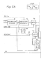
- Fig. 7 is a block circuit diagram illustrating a stepping feed control circuit for carrying out the method for controlling the stepping feed of an information medium according to the present invention. That is, the elements which are the same as those of Fig. 4 are denoted by the same references.
- a one-stripe feed quantity generator circuit 41, a backward quantity counter 42, a gate circuit 43, a flip-flop 44 and a gate circuit 45 are added.
- a signal pulse DATA END performs the similar action as the start pulse START in Fig. 4 and in addition, a signal pulse REVERSE is used for rotating the take-up motor 16 in the reverse direction.
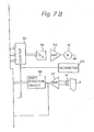
- Fig. 7 The operation of the circuit of Fig. 7 will be explained with reference to Figs. 8A through 8 H .
- the operation before the time t 1 when the recording or reading operation of the data signal DATA upon the recording track T n is completed, is the same as that of the circuit of Fig. 4.
- the data recording device 6 (Fig. 1) generates the signal pulse DATA END in synchronization with the output of the rotational angle detector (not shown) of the magnetic head 14.
- a feed quantity M of the one-stripe feed quantity generator circuit 41 is set in the counter 33 through the gate circuit 32 so that the D/A converter 34 produces an analog output voltage DA as illustrated in Fig. 8E.
- checking of the content of the read data signal DATA in the recording track T is completed prior to the completion of the feed of the magnetic tape T. That is, at a time t 2 when checking of the content of the read data signal DATA is completed, when no error is detected as a result of checking, the upper unit (not shown) produces a step instruction STEP as illustrated in Fig. 8B. This step instruction STEP is detected by the instruction decoder 31 so that the flip-flop 44 is reset as illustrated in Fig. 8C. Therefore, after the time t 2 , even when a signal pulse REVERSE is applied to the gate circuit 45, the gate circuit 45 cannot be opened and accordingly, the gate circuit 43 also cannot be opened.
- the contents of the counter 33 changes successively as illustrated in Fig. 8E; in other words, the feed of the magnetic tape T in the forward direction is cpntinued, so that the magnetic head 14 is located at the next recording track T n+1 as illustrated in Fig. 8G.
- the magnetic head 14 reads an identification signal ID', leading servo signals LS 1 ' and LS 2 ', data signal DATA' and the like, from the recording track T nTl , as illustrated in Fig. 8H.
- the analog voltage DA of the D/A converter 34 becomes negative so that the take-up motor 16 rotates in the reverse direction. That is, the take-up motor 16 rotates in the reverse direction by the amount of the feed given by the backward counter 42 and, as a result, the magnetic head 14 is again located at the recording track T n , as illustrated in Fig. 9G. Therefore, after that, the same read signal is obtained by rotating the magnetic head 14.
- the upper unit does not generate a step instruction STEP, so that the magnetic head 14 remains at the same recording track.
- the magnetic head 14 may be shifted a little from the center of the recording track T . It is preferable that such a shift is corrected at the end of the feed operation, regardless of the result of checking.
- an embodiment in which such a shift is corrected simultaneously with the feed operation of the magnetic tape T will be explained.
- Fig. 10 is a timing waveform diagram for explaining the correction of the stepping quantity according to the present invention.
- M is a distance between the recording tracks T n and T n+1 ;
- T n ' is an initial position of the magnetic head 14;
- X 0 , X 1 and X 2 are the contents of the counter 33 at the times t 1 , t and t 2 , respectively;
- ⁇ and y are shift quantities from the center of the recording track T n at the times t s and t 2 , respectively.
- a one-stripe feed quantity X 0 corresponding to the distance M is set in the counter 33.
- a shift quantity y of the magnetic head 14 with regard to the recording track T n can be represented by Therefore, as will be understood from Fig. 10, when no error is detected as a result of checking the content of the data signal DATA, M-y is set in the counter 33 at the time t 2 , so that the shift correction is also completed at the time t 3 when the feed operation is completed.
- -y is set in the counter 33 at the time t 2 , so that the shift correction is also completed at the time t 3 when the feed operation is completed.
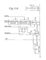
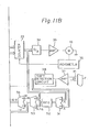
- F ig. 11 is a block circuit diagram illustrating another stepping feed control circuit for carrying out the method for controlling the stepping feed of an information medium according to the present invention, in which the shift correction can be effected simultaneously with the feed operation of the magnetic tape.
- the elements which are the same as those of Fig. 7 are denoted by the same references.
- an adder 51, a register 52, a subtracter 53, an adder 54 and a selection circuit 55 are provided instead of the backward counter 42 of Fig. 7.
- the selection circuit 55 selects the output M-y of the adder 54, since the output of the flip-flop 44 is changed from "1" to "0" due to the step instruction STEP. As a result, the value M-y is set in the counter 33 through the gate circuit 43. On the other hand, when the feed of the magnetic tape T is reversed, the output of the flip-flop 44 remains at "1", so that the selection circuit 55 selects the output -y of the subtracter 53 when a signal pulse REVERSE is generated. As a result, the value -y is set in the counter 33 through the gate 43.
- the method according to the present invention is-applied to an information medium, such as a magnetic tape or the like on which recording tracks are formed by stripes which run diagonally across the information medium; however, the method according to the present invention can be also applied to an information medium on which recording tracks are formed by stripes which run vertically across the information medium.
- the method for controlling the stepping feed of an information medium, such as a magnetic tape or the like, according to the present invention has an advantage, as compared with the conventional method, in that the time required for the feed operation of the magnetic tape is substantially reduced and, accordingly, the read speed of data is increased, since the feed of the magnetic tape begins immediately after the recording or reading operation of a data signal upon a predetermined recording track is completed and without waiting for the result of the checking of the data signal.
- the magnetic tape reciprocates within a distance which is about half of one stripe of the magnetic tape.
- the time required for the feed operation is the same as the time required for the feed operation when the recording or reading operation is performed upon the next recording track.
- such a time belongs to a time-period in which the recording or reading operation is not performed and, accordingly, the time does not affect the data processing time at all.
Abstract
Applications Claiming Priority (2)
| Application Number | Priority Date | Filing Date | Title |
|---|---|---|---|
| JP10589680A JPS5733417A (en) | 1980-07-31 | 1980-07-31 | Step feed controlling system of information medium |
| JP105896/80 | 1980-07-31 |
Publications (3)
| Publication Number | Publication Date |
|---|---|
| EP0056823A1 true EP0056823A1 (fr) | 1982-08-04 |
| EP0056823A4 EP0056823A4 (fr) | 1982-11-25 |
| EP0056823B1 EP0056823B1 (fr) | 1986-01-08 |
Family
ID=14419653
Family Applications (1)
| Application Number | Title | Priority Date | Filing Date |
|---|---|---|---|
| EP81902246A Expired EP0056823B1 (fr) | 1980-07-31 | 1981-07-30 | Procede de commande de transfert pas a pas d'un support d'information |
Country Status (5)
| Country | Link |
|---|---|
| US (1) | US4492991A (fr) |
| EP (1) | EP0056823B1 (fr) |
| JP (1) | JPS5733417A (fr) |
| AU (1) | AU548844B2 (fr) |
| WO (1) | WO1982000540A1 (fr) |
Cited By (2)
| Publication number | Priority date | Publication date | Assignee | Title |
|---|---|---|---|---|
| EP0185425A1 (fr) * | 1984-12-17 | 1986-06-25 | Koninklijke Philips Electronics N.V. | Méthode et appareil pour décoder une suite d'informations, accessible par répétition et protégée par un code de correction de symbole |
| EP0212592A2 (fr) * | 1985-08-22 | 1987-03-04 | Deutsche Thomson-Brandt GmbH | Enregistreur, en particulier pour un signal numérique |
Families Citing this family (14)
| Publication number | Priority date | Publication date | Assignee | Title |
|---|---|---|---|---|
| JPS60129429U (ja) * | 1984-02-08 | 1985-08-30 | タキロン株式会社 | 化粧板 |
| AU622626B2 (en) * | 1987-06-03 | 1992-04-16 | Sony Corporation | Method of processing data |
| US5142422A (en) * | 1989-11-09 | 1992-08-25 | Exabyte Corporation | Dual channel helical recorder |
| US5050018A (en) * | 1990-04-19 | 1991-09-17 | Exabyte Corporation | Apparatus and method for reading helically recorded tracks and rereading tracks as necessary |
| US6246551B1 (en) | 1998-10-20 | 2001-06-12 | Ecrix Corporation | Overscan helical scan head for non-tracking tape subsystems reading at up to 1X speed and methods for simulation of same |
| US6367047B1 (en) | 1998-10-20 | 2002-04-02 | Ecrix | Multi-level error detection and correction technique for data storage recording device |
| US6307701B1 (en) | 1998-10-20 | 2001-10-23 | Ecrix Corporation | Variable speed recording method and apparatus for a magnetic tape drive |
| US6381706B1 (en) | 1998-10-20 | 2002-04-30 | Ecrix Corporation | Fine granularity rewrite method and apparatus for data storage device |
| US6421805B1 (en) | 1998-11-16 | 2002-07-16 | Exabyte Corporation | Rogue packet detection and correction method for data storage device |
| US6603618B1 (en) | 1998-11-16 | 2003-08-05 | Exabyte Corporation | Method and system for monitoring and adjusting tape position using control data packets |
| US6308298B1 (en) | 1998-11-16 | 2001-10-23 | Ecrix Corporation | Method of reacquiring clock synchronization on a non-tracking helical scan tape device |
| US6367048B1 (en) | 1998-11-16 | 2002-04-02 | Mcauliffe Richard | Method and apparatus for logically rejecting previously recorded track residue from magnetic media |
| US6364234B1 (en) | 2000-03-10 | 2002-04-02 | Michael Donald Langiano | Tape loop/slack prevention method and apparatus for tape drive |
| US6624960B1 (en) | 2000-03-10 | 2003-09-23 | Exabyte Corporation | Current sensing drum/cleaning wheel positioning method and apparatus for magnetic storage system |
Family Cites Families (6)
| Publication number | Priority date | Publication date | Assignee | Title |
|---|---|---|---|---|
| US2977047A (en) * | 1957-12-13 | 1961-03-28 | Honeywell Regulator Co | Error detecting and correcting apparatus |
| US3274574A (en) * | 1962-12-24 | 1966-09-20 | Ibm | Backhitching tape control |
| JPS5130770B1 (fr) * | 1970-12-28 | 1976-09-02 | ||
| JPS5115415B1 (fr) * | 1970-12-28 | 1976-05-17 | ||
| US3932894A (en) * | 1974-03-14 | 1976-01-13 | International Business Machines Corporation | Magnetic record member for use with rotating head magnetic recording apparatus |
| DE2841106B1 (de) * | 1978-09-21 | 1979-11-29 | Siemens Ag | Verfahren und Schaltungsanordnung zum Verkuerzen der Informationsblockluecken des Magnetbandes bzw. zum Verringern der Belastung des Antriebssystems in Magnetbandgeraeten |
-
1980
- 1980-07-31 JP JP10589680A patent/JPS5733417A/ja active Granted
-
1981
- 1981-07-30 EP EP81902246A patent/EP0056823B1/fr not_active Expired
- 1981-07-30 AU AU74526/81A patent/AU548844B2/en not_active Ceased
- 1981-07-30 US US06/364,850 patent/US4492991A/en not_active Expired - Fee Related
- 1981-07-30 WO PCT/JP1981/000172 patent/WO1982000540A1/fr active IP Right Grant
Non-Patent Citations (1)
| Title |
|---|
| See references of WO8200540A1 * |
Cited By (3)
| Publication number | Priority date | Publication date | Assignee | Title |
|---|---|---|---|---|
| EP0185425A1 (fr) * | 1984-12-17 | 1986-06-25 | Koninklijke Philips Electronics N.V. | Méthode et appareil pour décoder une suite d'informations, accessible par répétition et protégée par un code de correction de symbole |
| EP0212592A2 (fr) * | 1985-08-22 | 1987-03-04 | Deutsche Thomson-Brandt GmbH | Enregistreur, en particulier pour un signal numérique |
| EP0212592A3 (en) * | 1985-08-22 | 1989-05-10 | Deutsche Thomson-Brandt Gmbh | Recorder, particularly for a digital signal |
Also Published As
| Publication number | Publication date |
|---|---|
| AU548844B2 (en) | 1986-01-02 |
| WO1982000540A1 (fr) | 1982-02-18 |
| EP0056823B1 (fr) | 1986-01-08 |
| EP0056823A4 (fr) | 1982-11-25 |
| JPS5733417A (en) | 1982-02-23 |
| AU7452681A (en) | 1980-03-02 |
| US4492991A (en) | 1985-01-08 |
| JPH0252349B2 (fr) | 1990-11-13 |
Similar Documents
| Publication | Publication Date | Title |
|---|---|---|
| EP0056823A1 (fr) | Procede de commande de transfert pas a pas d'un support d'information | |
| US6459540B1 (en) | Variable speed recording method and apparatus for a magnetic tape drive | |
| JPS585461B2 (ja) | 磁気テ−プ記録装置 | |
| US5276566A (en) | Recording/reading high density data tracks with backward compatibility | |
| JPH0690826B2 (ja) | 信号再生装置 | |
| EP0429727B1 (fr) | Enregistreur de données | |
| US3852814A (en) | Magnetic tape recording and/or reproducing apparatus having means to relocate a previous termination of recording or reproducing | |
| EP0176326A2 (fr) | Appareil et procédé de détection adaptive de fin de bande | |
| JP2685593B2 (ja) | 磁気記録再生装置 | |
| CA1093688A (fr) | Methode pour resserrer la bande magnetique dans une bobine | |
| US20040156140A1 (en) | Recording medium,recording method, and recorder | |
| JPH06131618A (ja) | 磁気テ−プにおける基準信号の記録再生方法 | |
| JP4016173B2 (ja) | テープドライブ装置、テープドライブ方法 | |
| JP3520710B2 (ja) | 磁気テープ記録再生装置 | |
| US5299074A (en) | System for positioning a head in a transverse reference position on a multitrack digital magnetic tape | |
| JPH08279250A (ja) | ディジタル信号記録方法とディジタル信号書き換え方法及びfm音声信号/ディジタル信号記録兼用ドラム装置とディジタル信号磁気記録再生装置 | |
| JPH0834044B2 (ja) | ヘリカルスキャン形磁気テープ記憶装置 | |
| JPH10106164A (ja) | データ記憶装置 | |
| JPS5834020B2 (ja) | テ−プ送出方式 | |
| JP2585363B2 (ja) | ヘリキャルスキャン形磁気テープ記憶装置 | |
| JP3249259B2 (ja) | デジタル信号記録装置及び再生装置 | |
| JP3191507B2 (ja) | ビデオテープレコーダ | |
| JPS5822819B2 (ja) | 記録媒体スキユ−訂正装置 | |
| JPH0762924B2 (ja) | 磁気記録再生装置のテ−プ頭出し機構 | |
| JPH06103563B2 (ja) | 磁気記録再生装置 |
Legal Events
| Date | Code | Title | Description |
|---|---|---|---|
| PUAI | Public reference made under article 153(3) epc to a published international application that has entered the european phase |
Free format text: ORIGINAL CODE: 0009012 |
|
| 17P | Request for examination filed |
Effective date: 19820322 |
|
| AK | Designated contracting states |
Designated state(s): DE FR GB |
|
| GRAA | (expected) grant |
Free format text: ORIGINAL CODE: 0009210 |
|
| AK | Designated contracting states |
Designated state(s): DE FR GB |
|
| ET | Fr: translation filed | ||
| REF | Corresponds to: |
Ref document number: 3173436 Country of ref document: DE Date of ref document: 19860220 |
|
| PLBE | No opposition filed within time limit |
Free format text: ORIGINAL CODE: 0009261 |
|
| STAA | Information on the status of an ep patent application or granted ep patent |
Free format text: STATUS: NO OPPOSITION FILED WITHIN TIME LIMIT |
|
| 26N | No opposition filed | ||
| PGFP | Annual fee paid to national office [announced via postgrant information from national office to epo] |
Ref country code: GB Payment date: 19920717 Year of fee payment: 12 |
|
| PGFP | Annual fee paid to national office [announced via postgrant information from national office to epo] |
Ref country code: FR Payment date: 19920730 Year of fee payment: 12 |
|
| PGFP | Annual fee paid to national office [announced via postgrant information from national office to epo] |
Ref country code: DE Payment date: 19920922 Year of fee payment: 12 |
|
| PG25 | Lapsed in a contracting state [announced via postgrant information from national office to epo] |
Ref country code: GB Effective date: 19930730 |
|
| GBPC | Gb: european patent ceased through non-payment of renewal fee |
Effective date: 19930730 |
|
| PG25 | Lapsed in a contracting state [announced via postgrant information from national office to epo] |
Ref country code: FR Effective date: 19940331 |
|
| PG25 | Lapsed in a contracting state [announced via postgrant information from national office to epo] |
Ref country code: DE Effective date: 19940401 |
|
| REG | Reference to a national code |
Ref country code: FR Ref legal event code: ST |