EP0054449B1 - Lève-glace - Google Patents
Lève-glace Download PDFInfo
- Publication number
- EP0054449B1 EP0054449B1 EP19810401779 EP81401779A EP0054449B1 EP 0054449 B1 EP0054449 B1 EP 0054449B1 EP 19810401779 EP19810401779 EP 19810401779 EP 81401779 A EP81401779 A EP 81401779A EP 0054449 B1 EP0054449 B1 EP 0054449B1
- Authority
- EP
- European Patent Office
- Prior art keywords
- window
- slideway
- rack
- pinion
- slide
- Prior art date
- Legal status (The legal status is an assumption and is not a legal conclusion. Google has not performed a legal analysis and makes no representation as to the accuracy of the status listed.)
- Expired
Links
- 239000000463 material Substances 0.000 claims description 4
- 230000002427 irreversible effect Effects 0.000 claims 2
- 239000011521 glass Substances 0.000 description 5
- 239000003638 chemical reducing agent Substances 0.000 description 4
- 238000010276 construction Methods 0.000 description 4
- 230000005540 biological transmission Effects 0.000 description 3
- 230000000694 effects Effects 0.000 description 2
- 239000002991 molded plastic Substances 0.000 description 2
- 230000002093 peripheral effect Effects 0.000 description 2
- 239000004033 plastic Substances 0.000 description 2
- 230000000717 retained effect Effects 0.000 description 2
- 238000003466 welding Methods 0.000 description 2
- 230000000712 assembly Effects 0.000 description 1
- 238000000429 assembly Methods 0.000 description 1
- 230000000903 blocking effect Effects 0.000 description 1
- 230000000295 complement effect Effects 0.000 description 1
- 238000002788 crimping Methods 0.000 description 1
- 230000014759 maintenance of location Effects 0.000 description 1
- 238000004519 manufacturing process Methods 0.000 description 1
- 230000013011 mating Effects 0.000 description 1
- 239000002184 metal Substances 0.000 description 1
- 229910052751 metal Inorganic materials 0.000 description 1
- 238000005096 rolling process Methods 0.000 description 1
Images


Classifications
-
- E—FIXED CONSTRUCTIONS
- E05—LOCKS; KEYS; WINDOW OR DOOR FITTINGS; SAFES
- E05F—DEVICES FOR MOVING WINGS INTO OPEN OR CLOSED POSITION; CHECKS FOR WINGS; WING FITTINGS NOT OTHERWISE PROVIDED FOR, CONCERNED WITH THE FUNCTIONING OF THE WING
- E05F11/00—Man-operated mechanisms for operating wings, including those which also operate the fastening
- E05F11/38—Man-operated mechanisms for operating wings, including those which also operate the fastening for sliding windows, e.g. vehicle windows, to be opened or closed by vertical movement
- E05F11/44—Man-operated mechanisms for operating wings, including those which also operate the fastening for sliding windows, e.g. vehicle windows, to be opened or closed by vertical movement operated by one or more lifting arms
- E05F11/445—Man-operated mechanisms for operating wings, including those which also operate the fastening for sliding windows, e.g. vehicle windows, to be opened or closed by vertical movement operated by one or more lifting arms for vehicle windows
-
- E—FIXED CONSTRUCTIONS
- E05—LOCKS; KEYS; WINDOW OR DOOR FITTINGS; SAFES
- E05Y—INDEXING SCHEME ASSOCIATED WITH SUBCLASSES E05D AND E05F, RELATING TO CONSTRUCTION ELEMENTS, ELECTRIC CONTROL, POWER SUPPLY, POWER SIGNAL OR TRANSMISSION, USER INTERFACES, MOUNTING OR COUPLING, DETAILS, ACCESSORIES, AUXILIARY OPERATIONS NOT OTHERWISE PROVIDED FOR, APPLICATION THEREOF
- E05Y2900/00—Application of doors, windows, wings or fittings thereof
- E05Y2900/50—Application of doors, windows, wings or fittings thereof for vehicles
- E05Y2900/53—Type of wing
- E05Y2900/55—Windows
Definitions
- the present invention relates to window winders for motor vehicles.
- window regulators Most of the usual window regulators have a construction which, to a large extent, is adapted to the particularities of the vehicle door which has to be fitted. In the same vehicle, depending on whether the door is at the front or rear, or whether it is on the right or on the left, different basic components for the window regulators must, most often, be provided . Likewise, in general, the basic structure of a window regulator must be established according to the drive mode, manual or by electric motor. Such specialization in the construction of window regulators obviously leads to manufacturing complications and increased costs.
- window regulators with symmetrical crossed arms such as that described in application EP-A-0 018 914, in the name of the applicant, which comprises a hinge nut carried by a slide guided in an essentially vertical slide whose axis coincides with the axis of symmetry. Due to the symmetry of the arms, the window lifter can, without particular difficulty, be mounted either on a right door or on a left door.
- the slider and the slide of the known window lifter are clearly different, depending on whether the drive is carried out manually, in which case the slide is a tubular sheath for guiding a flexible control cable, or else by means of an electric motor, the slider then constituting a nut engaged with a screw rotated by the motor.
- the object of the invention is to provide a window regulator which is almost completely trivialized, that is to say the basic components of which can be used as such for equipping any vehicle door.
- the invention relates to a window lifter of the type described in EP-A-0018914, comprising at least one inclined arm pivotally mounted at an intermediate point of its length, on a hinge pin carried by a slide which is guided longitudinally in a U or C profile forming a substantially vertical slide and which carries a rack engaged with a drive pinion through a lateral opening of the U or C profile, the two ends of the arms being guided in the slides perpendicular to the axis of the slide, which are respectively fixed to the bottom of the glass and fixed, the fixed slide defining a central line on either side of which the arm can move, which is characterized in that the bottom of the vertical slide profile has a flat or cutout at the right of which the material is deformed towards the inside of said slide so as to form the bottom wall of a housing open laterally by t and other of said wall, and to delimit an opening through which a pinion forming part of a drive module, assembled to the slide is mounted inside the profile in the housing and engaged with the rack.
- This arrangement defines a basic mechanism for the window regulator with which a drive module can be assembled, quite simply, meeting any particular conditions, particularly with regard to the configuration of the vehicle door, the position of the seats and the mode of control, manual or engine-driven, of the window.
- the rack pinion is introduced from the rear through the mounting opening in the bottom of the profile of the slide.
- the drive module may include a housing or an assembly plate which can be pressed onto the rear face of the profile bottom and be fixed for example by crimping or bolting.
- the drive module can be direct manual control and include an actuating crank and an output gear wheel integral with the rack pinion.
- Another possible module is constituted by a motor-reducer, the assembly plate of which can be fixed by bolting, both on the bottom of the C-profile and on the median surface, of generally planar shape, of a mount in which the one or two fixed slides are formed perpendicular to the axis of symmetry.
- an advantageous solution proposed by the invention consists in providing between the actuating crank and the pinion of rack and pinion a transmission by toothed belt, comprising a toothed driving pulley, integral with the crank, and a receiving toothed pulley secured to the rack pinion and in which is preferably incorporated an irreversibility brake.
- This arrangement allows, thanks to the position of the pinion centered on the axis of symmetry, to mount the transmission on one side or the other of this axis and to place the crank, by means of the choice of an appropriate length of belt. , at any distance from the axis of symmetry.
- the slide is advantageously a molded plastic part, which, over at least part of its length, has a U-shaped profile ensuring guidance in the slide, the rack being formed in the internal face of one of the branches of the profile .
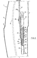
- the window regulator according to the invention is intended to equip a door 1 of a motor vehicle (fig.
- each slide has a U-shaped profile, the opening of which faces the internal panel 4 and the sides of which guide a domed roller 23 rotatably mounted at one of the ends 24 of a corresponding arm 26 or 27.
- the two arms 26, 27, of equal length, are connected to each other, a short distance from their other end 28, by a hinge 29 carried by a slide 30 guided in a rectilinear slide 31, in principle vertical.
- the crossed arms 26, 27 carry a roller 51 which has the same convex shape as the rollers 23 disposed at the end 24, of the arms and which is engaged in rolling contact with the sides of one of two slides central units 54 perpendicular to the axis YY of the slide 31, whose U-shaped profile is open towards the external panel 3, and which are part of a frame 50 whose central part 55, of generally planar shape, is fixed by bolting at 56 on the internal panel 4.
- Rigid ribs 55a are however formed in the flat surface 55.
- the axis XX common to the slides 54 constitutes a horizontal central line that the arms 26, 27 can cross, despite their crossed mounting , during their angular deflections under the effect of the movement of the slide 30, thanks to the fact that one of the arms, 26, consists of two half-arms 26a, 26b, located on either side of the other arm, 27, which is in one piece, and made integral with each other in worm tu of the special arrangement of the articulation 29 connecting the arms at their crossing point (fig. 3).
- This articulation 29 comprises a pin 57 which is integral with the slide 30 and is engaged in sliding contact inside a sleeve 58 passing through holes 59, 61, 62 made respectively in the half-arm 26a, the arm 27 and the half-arm 26b, and the peripheral surface of which comprises a cylindrical part 63 engaged in contact with the hole 61, of circular shape, of the arm 27 for premitting a relative rotation, and on either side of this cylindrical part, parts prismatic 64 in engagement with the square outline of the holes 59, 62 to ensure by keying a blocking in relative rotation of the half-arms 26a, 26b.
- the arms 26, 27, which are symmetrical with respect to the axis YY of the slide 31 and therefore make with the central line XX equal angles and in opposite directions, constitute thin blades which make them flexible, which allows them to adapting to the curve of the glass 9. These arms can also undergo translational movements along the pin 57, integrally with the sleeve 58.
- the slide 31 forms a C-shaped section open towards the external panel 3, the bottom 34 of which is fixed, for example by welding, to the flat central part 55 of the frame 50.
- the slide 30, which preferably constitutes a molded plastic part, has from its upper end and over most of its length, a U-shaped profile, the two branches of which are guided in sliding contact with the bottom 34, the sides 35 and the edges 36 of the C-shaped section 31.
- a toothing 38 constitutes a rack for engaging a drive pinion.
- the toothing 38 is preferably molded with the slide but it can also be formed by an insert, for example made of metal.
- a housing 39 is provided in the slide 31.
- This housing which is located in part in line with a notch 55b of the frame 50, is constituted by a cavity delimited by a part cut at 40 in the bottom 34 of the profile 31 and deformed towards the inside of the latter by so as to define a central flat wall 41 between two lateral openings.
- the wall 41 is parallel to the bottom 34 but is offset enough to be on the opposite side of the rack 38, that is to say in the vicinity of the bottom of the internal cavity of the slide, as shown in Figure 2.
- It is in addition pierced with a square hole 47 in which is embedded a bearing 48 made of plastic material with a low coefficient of friction, for the reception of the pin-forming end of the rack pinion.
- projections 31a forming a stop are formed at the lower end of the section 31.
- the window regulator according to the invention can be considered to be of modular construction, in the sense that the basic structure, which has been described with reference to FIGS. 1 to 3, can be combined with different mechanical assemblies, or modules, for meet specific conditions of use.
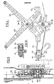
- a module essentially comprising a rack pinion 70 and a receiving toothed pulley 71, secured to this pinion and connected by a toothed belt 72 to a toothed driving pulley 73 mounted on the internal panel 4 and the shaft 74 of which receives an actuating crank 76.
- a cup 78 comprising a peripheral flange 79 fixed, for example by welding, on one of the faces of a support plate 81 which, at its two ends, is provided of a hole 82 through which the rim 32a of the respective holes 32 of the profile bottom 34 is crimped, thus ensuring the connection of the profile with the plate 81.
- the latter also comprises an opening in which is embedded a bearing 83 made of material plastic with a low coefficient of friction, which receives a cylindrical bearing 84 of the pinion 70, the end journal 86 of which is itself engaged in the bearing 48 of the wall 41.
- the hub 87 of the toothed pulley is fixed by fitting, or by splines , on an extension 88, of smaller diameter, of the bearing surface 84, the axial retention towards the internal panel 4 being ensured by a mating of the end 89 of the pinion opposite the pin 86.
- an irreversibility brake 91 is disposed inside the bowl 78.
- This brake is of conventional construction and essentially comprises a spring 92 inserted by force and under tension in the bowl 78 to ensure the immobilization of the pulley, which can however rotate freely when a torque is applied to it, by the effect of a loosening of the spring due to the action of a fork 93, inside the spring, which is secured to the hub 87 and is engaging the ends of the spring 92.
- the driving pulley 73 is fixed to the panel 4 by means of a stirrup 94 with uneven branches, between which the shaft 74 journals (fig. 6).
- the mounting point of the stirrup 94 can be chosen at will both in height and in distance relative to the axis YY of the slide 31, this distance being determined by the length of the toothed belt 72.
- the mounting is provided on the left of the YY axis in FIG. 4, but it could obviously be produced on the right, as indicated in broken lines in 72 ′.
- the irreversibility brake 91 could, of course, be incorporated into the driving pulley 73 instead of being incorporated into the receiving pulley 71.
- the module adopted in Figures 7 and 8 is a direct control mechanism comprising in a housing 96 a pinion 97, whose shaft 98 receives an actuating crank 76, and which is engaged with a toothed wheel 99 with which makes body the rack pinion 70, the pin 86 of which is engaged, as in FIG. 5, in the bearing 48.
- the housing 96 has two end wings 101 which are crimped at 32a on the bottom of the slide 34, in the same way as the support plate 81 of FIG. 5.
- An irreversibility brake 91 is mounted in the housing 96, between a shoulder 98a of the shaft 98 and the pinion 97.
- the housing 96 could be mounted in a position offset by 180 ° with respect to the position shown, provided that corresponding anchor points are provided in the profile bottom 34.
- the module incorporated into the basic structure is constituted by a gear motor 105 whose output element is the rack pinion 70.
- This pinion is engaged in the housing 39, as in the previous examples, and the assembly plate 106 of the motor-reducer 105 is fixed by bolting, or by equivalent means, on the one hand to the points 33 of the flat central part 55 of the frame 50, on the other hand through the lower bore 32 of the profile bottom 34.
- the assembly plate 106 as is the case of the support plate 81 (fig. 5) and of the housing 96 (fig. 8), is applied against the flat bottom 34 of the profile 31 .
- the support plate 81 is replaced by a casing 108, generally of omega shape, the wings 109 of which are also crimped at 32a on the profile bottom 34 , and in an opening 111 from which the end 90, opposite the pin 86, of the pinion 70 revolves. Furthermore, the end face of the pulley 71 has sliding contact with the adjacent wall of the casing 108.
- the stroke of the slide 30 forming a rack is approximately 140 mm, which is small compared with that, which should be of the order of 400 mm, of the rack described in the application FR 2 310461 cited above.
- the invention is not limited to the window lifter with crossed arms shown in the figures res 1 to 6, but also extends to a single-arm window lift pivotally mounted on an axis carried by a slide such as that shown in FIG. 8.
- the lower edge 14 of the glass is embedded and retained in a central horizontal slide 117, with a U-shaped profile, the sides of which guide the roller 23 rotatably mounted at the end of the arm 126.
- the roller 51 carried by the opposite end of the arm 126, moves, like those arms 26, 27, in a slide 54 of a half-frame 50 fixed, on the one hand on the internal panel 4, and on the other hand on the profile 31.
- the arm 126 pivots directly on the pin 57 of the slide 30, under the action of a pinion control mechanism 70 mounted in the housing 39 of the bottom 34 of the profile. It thus moves in the same way as the arm 26 or 27, on either side of the line formed by the fixed slide 54.
Landscapes
- Window Of Vehicle (AREA)
- Power-Operated Mechanisms For Wings (AREA)
- Glass Compositions (AREA)
Applications Claiming Priority (2)
| Application Number | Priority Date | Filing Date | Title |
|---|---|---|---|
| FR8025279 | 1980-11-28 | ||
| FR8025279A FR2495213A1 (fr) | 1980-11-28 | 1980-11-28 | Leve-glace |
Publications (2)
| Publication Number | Publication Date |
|---|---|
| EP0054449A1 EP0054449A1 (fr) | 1982-06-23 |
| EP0054449B1 true EP0054449B1 (fr) | 1984-05-02 |
Family
ID=9248452
Family Applications (1)
| Application Number | Title | Priority Date | Filing Date |
|---|---|---|---|
| EP19810401779 Expired EP0054449B1 (fr) | 1980-11-28 | 1981-11-10 | Lève-glace |
Country Status (6)
| Country | Link |
|---|---|
| EP (1) | EP0054449B1 (enExample) |
| JP (1) | JPS587074A (enExample) |
| BR (1) | BR8107747A (enExample) |
| DE (1) | DE3163422D1 (enExample) |
| ES (1) | ES8306822A1 (enExample) |
| FR (1) | FR2495213A1 (enExample) |
Cited By (1)
| Publication number | Priority date | Publication date | Assignee | Title |
|---|---|---|---|---|
| CN109025637A (zh) * | 2018-08-23 | 2018-12-18 | 内蒙古第机械集团股份有限公司 | 一种防弹车辆车门玻璃升降系统 |
Families Citing this family (2)
| Publication number | Priority date | Publication date | Assignee | Title |
|---|---|---|---|---|
| JPH0512581U (ja) * | 1991-07-29 | 1993-02-19 | 株式会社大井製作所 | ウインドウレギユレータ装置 |
| RU2176014C1 (ru) * | 2000-05-22 | 2001-11-20 | Евсеенков Виктор Алексеевич | Электромеханический привод |
Family Cites Families (4)
| Publication number | Priority date | Publication date | Assignee | Title |
|---|---|---|---|---|
| US1916865A (en) * | 1931-10-05 | 1933-07-04 | Briggs & Stratton Corp | Window regulator |
| FR2127286A5 (enExample) * | 1971-03-03 | 1972-10-13 | Peugeot & Renault | |
| FR2310461A1 (fr) * | 1975-05-07 | 1976-12-03 | Keiper Kg | Leve-glace pour fenetre, notamment pour fenetre d'automobile |
| FR2455667A1 (fr) * | 1979-05-04 | 1980-11-28 | Paumellerie Electrique | Leve-glace |
-
1980
- 1980-11-28 FR FR8025279A patent/FR2495213A1/fr active Granted
-
1981
- 1981-11-10 DE DE8181401779T patent/DE3163422D1/de not_active Expired
- 1981-11-10 EP EP19810401779 patent/EP0054449B1/fr not_active Expired
- 1981-11-27 ES ES508071A patent/ES8306822A1/es not_active Expired
- 1981-11-27 BR BR8107747A patent/BR8107747A/pt unknown
- 1981-11-27 JP JP19045281A patent/JPS587074A/ja active Pending
Cited By (1)
| Publication number | Priority date | Publication date | Assignee | Title |
|---|---|---|---|---|
| CN109025637A (zh) * | 2018-08-23 | 2018-12-18 | 内蒙古第机械集团股份有限公司 | 一种防弹车辆车门玻璃升降系统 |
Also Published As
| Publication number | Publication date |
|---|---|
| FR2495213B1 (enExample) | 1983-11-18 |
| EP0054449A1 (fr) | 1982-06-23 |
| ES508071A0 (es) | 1983-06-01 |
| FR2495213A1 (fr) | 1982-06-04 |
| ES8306822A1 (es) | 1983-06-01 |
| JPS587074A (ja) | 1983-01-14 |
| BR8107747A (pt) | 1982-08-31 |
| DE3163422D1 (en) | 1984-06-07 |
Similar Documents
| Publication | Publication Date | Title |
|---|---|---|
| EP0018914B1 (fr) | Lève-glace | |
| FR2524407A1 (fr) | Tete d'assemblage matricee d'un element d'essuie-glace, son procede de fabrication et element d'essuie-glace la comportant | |
| EP0832799B1 (fr) | Dispositif d'essuyage d'une vitre de véhicule automobile comportant un dispositif perfectionné d'orientation d'un arbre d'entraínement | |
| EP0053960B1 (fr) | Dispositif de liaison latérale d'un balai d'essuie glace | |
| FR2811007A1 (fr) | Charniere avec arret de porte integre | |
| FR2753574A1 (fr) | Contacteur tournant a ruban, en particulier pour vehicules automobiles | |
| EP0054449B1 (fr) | Lève-glace | |
| EP0000297A1 (fr) | Lève-glace, notamment pour véhicules automobiles | |
| CA1301806C (fr) | Dispositif leve-vitre pour vehicule automobile | |
| FR2584036A1 (fr) | Balai d'essuie-glace a accrochage lateral pour vehicule automobile | |
| EP1347136B1 (fr) | Ensemble de support et de guidage pour porte coulissante et porte correspondante | |
| FR2462311A1 (fr) | Element d'essuie-glace, notamment pour vehicules automobiles | |
| FR2596096A1 (fr) | Dispositif d'entrainement d'une tige de commande d'actionneur de serrure notamment de serrure de porte de vehicule automobile, et serrure equipee d'un tel dispositif | |
| EP0007861B1 (fr) | Dispositif de réglage d'un rétroviseur notamment pour véhicule | |
| WO1981000235A1 (fr) | Bras d'essuie-glace soumis a l'action d'un ressort en compression | |
| FR2560570A1 (fr) | Dispositif essuie-glace pour vehicules automobiles notamment | |
| EP3461701B1 (fr) | Dispositif de connexion d'un balai d'essuyage a un bras d'entrainemant pour vehicule | |
| EP0566944A1 (fr) | Dispositif d'essuie-glace à bras de longueur active variable | |
| EP1590273A1 (fr) | Palette pour cha ne de convoyeur-------------------------- | |
| FR2792883A1 (fr) | Porte de vehicule automobile munie d'un organe mobile tel qu'un accoudoir | |
| WO1982002692A1 (fr) | Element d'essuie-glace assurant la liaison d'un bras d'essuie-glace avec un mecanisme d'entrainement et comportant un capuchon pivotant | |
| FR2785247A1 (fr) | Systeme d'essuyage pour un vehicule automobile | |
| EP0567389A1 (fr) | Bras d'essuie-glace incorporant au moins un ressort de pression de contact | |
| FR2846604A1 (fr) | Capot de coffre arriere pour un vehicule decouvrable a toit repliable | |
| FR2753575A1 (fr) | Contacteur tournant a ruban, notamment pour vehicules automobiles |
Legal Events
| Date | Code | Title | Description |
|---|---|---|---|
| PUAI | Public reference made under article 153(3) epc to a published international application that has entered the european phase |
Free format text: ORIGINAL CODE: 0009012 |
|
| AK | Designated contracting states |
Designated state(s): DE GB IT NL SE |
|
| 17P | Request for examination filed |
Effective date: 19820621 |
|
| ITF | It: translation for a ep patent filed | ||
| GRAA | (expected) grant |
Free format text: ORIGINAL CODE: 0009210 |
|
| AK | Designated contracting states |
Designated state(s): DE GB IT NL SE |
|
| PG25 | Lapsed in a contracting state [announced via postgrant information from national office to epo] |
Ref country code: SE Effective date: 19840502 Ref country code: NL Effective date: 19840502 |
|
| REF | Corresponds to: |
Ref document number: 3163422 Country of ref document: DE Date of ref document: 19840607 |
|
| NLV1 | Nl: lapsed or annulled due to failure to fulfill the requirements of art. 29p and 29m of the patents act | ||
| PLBE | No opposition filed within time limit |
Free format text: ORIGINAL CODE: 0009261 |
|
| STAA | Information on the status of an ep patent application or granted ep patent |
Free format text: STATUS: NO OPPOSITION FILED WITHIN TIME LIMIT |
|
| 26N | No opposition filed | ||
| PG25 | Lapsed in a contracting state [announced via postgrant information from national office to epo] |
Ref country code: DE Effective date: 19850801 |
|
| GBPC | Gb: european patent ceased through non-payment of renewal fee | ||
| PG25 | Lapsed in a contracting state [announced via postgrant information from national office to epo] |
Ref country code: GB Effective date: 19881118 |