EP0052752A2 - Ausstellvorrichtung für Fenster oder Türen - Google Patents
Ausstellvorrichtung für Fenster oder Türen Download PDFInfo
- Publication number
- EP0052752A2 EP0052752A2 EP81108527A EP81108527A EP0052752A2 EP 0052752 A2 EP0052752 A2 EP 0052752A2 EP 81108527 A EP81108527 A EP 81108527A EP 81108527 A EP81108527 A EP 81108527A EP 0052752 A2 EP0052752 A2 EP 0052752A2
- Authority
- EP
- European Patent Office
- Prior art keywords
- scissor
- frame
- scissor arm
- groove
- elongated hole
- Prior art date
- Legal status (The legal status is an assumption and is not a legal conclusion. Google has not performed a legal analysis and makes no representation as to the accuracy of the status listed.)
- Granted
Links
Images

Classifications
-
- E—FIXED CONSTRUCTIONS
- E05—LOCKS; KEYS; WINDOW OR DOOR FITTINGS; SAFES
- E05D—HINGES OR SUSPENSION DEVICES FOR DOORS, WINDOWS OR WINGS
- E05D15/00—Suspension arrangements for wings
- E05D15/48—Suspension arrangements for wings allowing alternative movements
- E05D15/52—Suspension arrangements for wings allowing alternative movements for opening about a vertical as well as a horizontal axis
- E05D15/5205—Suspension arrangements for wings allowing alternative movements for opening about a vertical as well as a horizontal axis with horizontally-extending checks
-
- E—FIXED CONSTRUCTIONS
- E05—LOCKS; KEYS; WINDOW OR DOOR FITTINGS; SAFES
- E05Y—INDEXING SCHEME ASSOCIATED WITH SUBCLASSES E05D AND E05F, RELATING TO CONSTRUCTION ELEMENTS, ELECTRIC CONTROL, POWER SUPPLY, POWER SIGNAL OR TRANSMISSION, USER INTERFACES, MOUNTING OR COUPLING, DETAILS, ACCESSORIES, AUXILIARY OPERATIONS NOT OTHERWISE PROVIDED FOR, APPLICATION THEREOF
- E05Y2900/00—Application of doors, windows, wings or fittings thereof
- E05Y2900/10—Application of doors, windows, wings or fittings thereof for buildings or parts thereof
- E05Y2900/13—Type of wing
- E05Y2900/148—Windows
Definitions
- the invention relates to an opening device for windows or doors, the wings of which can be rotated about a vertical axis and tilted about a horizontal axis, a scissor pivot bearing having an angle piece being arranged on a scissor arm on the end facing the frame, on the horizontal leg of the angle piece the scissor arm is articulated and the other end of the scissor arm is slidably mounted in an elongated hole in a scissor housing which can be fixed on the wing.
- An opening device of this type is known (DE-OS 28 39803). in which the horizontal leg of the contra-angle handpiece is screwed into the groove of the vertical frame spar with a slot nut inserted into the groove of the upper horizontal frame spar by means of two screws.
- the known fitting was installed in such a way that the entire opening device was first mounted on the sash frame, the sash frame was inserted into the frame and only then was the scissor-type pivot bearing attached to the frame.
- the invention has for its object to design an opening device of the type mentioned so that the assembly on the sash as well as on the frame can be done separately, dismantling the window sash in the installed state of the window without fitting parts in the frame is possible and that the angle piece of the upper pivot bearing can be positively fixed in a simple manner in the grooves of the frame.
- the scissor arm at its wing-side end has a rotatable over an angular range of 90 degrees, in the coupled position the longitudinal edges of the elongated hole of the scissor housing engaging collar bolts, rotatable at its frame end on an in the grooves of the Upper horizontal and the vertical spar on the pivot bearing side, angled piece is articulated, the vertical leg of the angular piece being positively screwed into the groove with a part engaging behind an edge strip of the groove of the vertical frame spar, then the horizontal leg can be inserted into the groove of the upper horizontal spar of the frame and can be fixed by means of a screw and the additional link of the scissor arm is inserted into a hole in the scissor housing with a bolt of great length.
- the collar bolt is connected in a rotationally fixed manner to a tab which has a cutout for receiving an actuating tool and, in the end positions, bears against stop parts of the scissor arm.
- the opening device of the tilt-and-turn window or the tilt-and-turn door has a scissor arm 1, which is provided at its wing-side end with a collar bolt 2, which is slidably mounted in an elongated hole 3 of a scissor housing 4, the scissor housing 4 being fastened to the casement 5.
- the collar bolt has flats 6 on two opposite sides and has a width in the region of these flats that is a little smaller than the width of the elongated hole 3.
- the collar bolt can thus be inserted into the elongated hole 3 and then pivoted through 90 degrees in be brought into a coupled position in which it engages behind the longitudinal edges of the elongated hole.
- the collar bolt is rotatably connected to a tab 7, which has a slot-like recess 8 for receiving an actuating tool.
- the flap 8 is rotatably supported together with the collar bolt 2 to one axis 9 in the leaf-side end of the scissor arm 1 and is located in the two end positions of a Conn g tone of the scissor arm 1 at.
- the stop parts are formed by an offset 10 of the scissor arm.
- the tab 7 runs in an arc on the side facing the crank 10.
- the end regions of the arcuate contour rest on the crank 10 in the end positions of the tab. 3 shows one end position before the collar bolt is inserted into the elongated hole 3 of the scissor housing 4.
- the other end position which results from a pivoting of the bracket 7 by 90 degrees, is shown in FIG. 2, in which the collar bolt is positively connected to the scissors housing 4.
- the tab 7 is arranged on the top of the scissor arm 1.
- An additional link 11 is articulated on the scissor arm 1 and is inserted with a bolt 12 into a bore in the scissor housing 4.
- the bolt 12 is riveted to the additional link 11 and extends almost over the entire height of the scissor housing 4, namely in the vicinity of a drive rod 13 guided through the scissor housing.
- the large length of the bolt 12 prevents the pivoting position of the Window or the door of the bolt can automatically slip out of its mounting hole.
- the possible long axial changes during operation are completely compensated for by the long design of the bolt. A secure coupling is guaranteed.
- the scissor arm 1 is rotatably mounted on the upper horizontal leg 13 of the angle piece 14, specifically on a pin 15. To fix the contra-angle. 14 on the frame, the vertical leg 16 is first positively fixed in the groove 17 of the vertical frame spar 18.
- the vertical leg 16 has a projecting part 19, in which the manner shown in FIGS. 5 and 6 is screwed into the groove 17 and, after being inserted into the groove, engages behind an edge strip 20 of the groove.
- Part 19 points to the free End up with a conical taper.
- the angle piece 14 is inserted upwards and the horizontal leg into the groove 21 of the upper horizontal frame spar 22.
- the leg 13 is equipped with an oblique threaded bore into which a threaded pin 23 is screwed, which is supported with its free end on the bottom of the groove 21 and presses an undercut 24 of the leg 13 behind the edge strip 25, so that the leg 13 in the groove 21 is positively fixed.
- the undercut 24 preferably extends over most of the length of the leg 13, so that there is a uniform transfer of force between the angle piece and the frame.
- the angle piece which is only fixed to the frame by a grub screw 23, is held in the corner region of the frame without play and in a positive manner in all directions.
- the display device can be mounted separately on the sash and on the frame. In addition to the simple assembly and disassembly and the good strength-related fixing of the upper scissor stay, there are also considerable material savings and manufacturing reductions compared to the known designs.
Landscapes
- Engineering & Computer Science (AREA)
- Mechanical Engineering (AREA)
- Hinges (AREA)
- Wing Frames And Configurations (AREA)
- Adornments (AREA)
- Heat Treatment Of Strip Materials And Filament Materials (AREA)
- Auxiliary Devices For And Details Of Packaging Control (AREA)
- Specific Sealing Or Ventilating Devices For Doors And Windows (AREA)
- Liquid Crystal (AREA)
Abstract
Description
- Die Erfindung bezieht sich auf eine Ausstellvorrichtung für Fenster oder Türen, deren Flügel um eine lotrechte Achse drehbar und um eine waagerechte Achse kippbar sind, wobei an einem Scherenarm an dem dem Blendrahmen zugewandten Ende ein ein Winkelstück aufweisendes Scherendrehlager angeordnet, an dem horizontalen Schenkel des Winkelstücks der Scherenarm angelenkt und das andere Ende des Scherenarms in einem Langloch eines am Flügel festlegbaren Scherengehäuses gleitbar gelagert ist.
- Es ist eine Ausstellvorrichtung dieser Art bekannt (DE-OS 28 39803). bei der der horizontale Schenkel des Winkelstücks nach dem Einsetzen des vertikalen Schenkels in die Nut des vertikalen Blendrahmenholms mit einem in die Nut des oberen horizontalen Blendrahmenholms eingelegten Nutenstein mittels zweier Schrauben verschraubt wird.
- Die Montage des bekannten Beschlages wurde so vorgenommen, daß die gesamte Ausstellvorrichtung zunächst am Flügelrahmen montiert, der Flügelrahmen in den Blendrahmen eingesetzt und erst dann die Befestigung des Scherendrehlagers am Blendrahmen durchgeführt wurde.
- Der Erfindung liegt die Aufgabe zugrunde, eine Ausstellvorrichtung der eingangs genannten Art so zu gestalten, daß die Montage am Flügel wie auch am Blendrahmen getrennt vorgenommen werden kann, eine Demontage des Fensterflügels in eingebautem Zustand des Fensters ohne Beschlagteile im Rahmen zu demontieren möglich ist und daß das Winkelstück des oberen Drehlagers in einfacher Weise in den Nuten des Blendrahmens formschlüssig festgelegt werden kann.
- Diese Aufgabe wird nach der Erfindung dadurch gelöst, daß der Scherenarm an seinem flügelseitigen Ende einen über einen Winkelbereich von 9o Grad drehbaren, in der gekoppelten Stellung die Längsränder des Langloches des Scherengehäuses hintergreifenden Bundbolzen aufweist, an seinem blendrahmenseitigen Ende drehbar an einem in den Nuten des oberen horizontalen und des drehlagerseitigen vertikalen Holms festlegbaren Winkelstück angelenkt ist, wobei zunächst der vertikale Schenkel des Winkelstücks mit einem eine Randleiste der Nut des vertikalen Blendrahmenholms hintergreifenden Teil in die Nut formschlüssig eindrehbar, dann der horizontale Schenkel in die Nut des oberen horizontalen Holms des Blendrahmens einführbar und mittels einer Schraube festlegbar ist und der Zusatzlenker des Scherenarms mit einem Bolzen großer Länge in eine Bohrung des Scherengehäuses eingesteckt ist.
- Bei einer vorteilhaften Ausführungsform ist der Bundbolzen drehfest mit einer Lasche verbunden, die eine Aussparung zur Aufnahme eines Betätigungswerkzeuges aufweist und in den Endstellungen an Anschlagteilen des Scherenarms anliegt.
- Ein Ausführungsbeispiel der Erfindung ist in den Zeichnungen dargestellt und wird im folgenden beschrieben.
- Es zeigen:
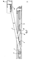
- Fig. 1 die zwischen dem Blend- und dem Flügelrahmen eines Drehkippfensters angeordnete Ausstellvorrichtung bei geschlossenem Flügel mit weggeschnittenen Teilen des Blend- und des Flügelrahmens,
- Fig. 2 das Fenster nach der Fig. 1'in der Kippstellung des Flügels,
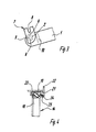
- Fig. 3 das flügelseitige Ende des Scherenarms vor dem Einsetzen des Bundbolzens in das Langloch des Scherengehäuses,
- Fig. 4 einen Schnitt nach der Linie IV - IV in Fig. 1
- Die Ausstellvorrichtung des Drehkippfensters oder der Drehkipptür weist einen Scherenarm 1 auf, der an seinem flügelseitigen Ende mit einem Bundbolzen 2 versehen ist, der in ein Langloch 3 eines Scherengehäuses 4 verschiebbar gelagert ist, wobei das Scherengehäuse 4 am Flügelrahmen 5 befestigt wird.
- Der Bundbolzen weist an zwei einander gegenüberliegenden Seiten Abflachungen 6 auf und besitzt im Bereich dieser Abflachungen eine Breite, die ein wenig kleiner ist als die Breite des Langloches 3. Der Bundbolzen kann somit in das Langloch 3 eingeführt und dann durch eine Verschwenkung um 9o Grad in eine gekoppelte Stellung gebracht werden, in der er die Längsränder des Langloches hintergreift.
- In dem dargestellten Ausführungsbeispiel ist der Bundbolzen drehfest mit einer Lasche 7 verbunden, die eine schlitzartige Aussparung 8 zur Aufnahme eines Betätigungswerkzeuges aufweist. Die Lasche 8 ist zusammen mit dem Bundbolzen 2 um eine, Achse 9 drehbar, im flügelseitigen Ende des Scherenarms 1 gelagert und liegt in den beiden Endstellungen an Anschlagteilen des Scherenarms 1 an.
- In dem dargestellten Ausfuhrungsbeispiel werden die Anschlagteile durch eine Kröpfung 1o des Scherenarms gebildet. Die Lasche 7 verläuft an der der Kröpfung 10 zugewandten Seite bogenförmig. Die Endbereiche der bogenförmigen Kontur liegen in den Endlagen der Lasche an der Kröpfung 10 an. In der Fig.3 ist die eine Endlage aufgezeigt, bevor der Bundbolzen in das Langloch 3 des Scherengehäuses 4 eingesetzt wird. Die andere Endlage, die sich durch eine Verschwenkung der Lasche 7 um 9o Grad ergibt, ist in der Fig. 2 aufgezeigt, in der der Bundbolzen formschlüssig mit dem Scherengehäuse 4 verbunden ist. Die Lasche 7 ist auf der Oberseite des Scherenarms 1 angeordnet.
- An dem Scherenarm 1 ist ein Zusatzlenker 11 angelenkt, der mit einem Bolzen 12 in eine Bohrung des Scherengehäuses 4 eingesteckt wird. Der Bolzen 12 ist an dem Zusatzlenker 11 fest angenietet und erstreckt sich nahezu über die gesamte Höhe des Scherengehäuses 4 und zwar bis in die Nähe einer durch das Scherengehäuse geführten Treibstange 13. Durch die große Länge des Bolzens 12 wird verhindert, daß bei einer Kippstellung des Fensters oder der Tür der Bolzen selbsttätig aus seiner Aufnahmebohrung herausrutschen kann. Durch die lange Ausführung des Bolzens werden die auftretenden, möglichen achsialen Veränderungen während des Betriebes vollständig ausgeglichen. Es wird eine sichere Kopplung gewährleistet.
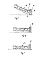
- Der Scherenarm 1 ist an dem oberen horizontalen Schenkel 13 des Winkelstücks 14, und zwar an einem Zapfen 15 drehbar gelagert. Zur Festlegung des Winkelstücks. 14 an dem Blendrahmen wird zunächst der vertikale Schenkel 16 formschlüssig in der Nut 17 des vertikalen Blendrahmenholms 18 festgelegt.
- Der vertikale Schenkel 16 weist ein vorspringendes'Teil 19 auf, in der das in den Figuren 5 und 6 dargestellten Weise in die Nut 17 eingedreht wird und nach dem Einsetzen in die Nut eine Randleiste 2o der Nut hintergreift. Das Teil 19 weist zum freien Ende eine konische Verjüngung auf.
- Nach dem Einsetzen bzw. Eindrehen des vertikalen Schenkels 16 in die Nut 17 des Blendrahmenholms, wird das Winkelstück 14 nach oben und der horizontale Schenkel in die Nut 21 des oberen horizontalen Blendrahmenholms 22 eingeschoben. Der Schenkel 13 ist mit einer schräg verlaufenden Gewindebohrung ausgerüstet, in die ein Gewindestift 23 eingeschraubt wird, der sich mit seinem freien Ende am Boden der Nut 21 abstützt und eine Hinterschneidung 24 des Schenkels 13 hinter die Randleiste 25 drückt, so daß der Schenkel 13 in der Nut 21 formschlüssig festgelegt wird. Die Hinterschneidung 24 erstreckt sich vorzugsweise über den größten Teil der Länge des Schenkels 13, so daß sich eine gleichmäßige Kraftabtragung zwischen dem Winkelstück und dem Blendrahmen ergibt. Das Winkelstück, das nur durch einen Gewindestift 23 am Blendrahmen festgelegt wird, wird im Eckbereich des Blendrahmens spielfrei und in allen Richtungen formschlüssig gehalten.
- Die Montage der Ausstellvorrichtung kann am Flügel wie auch am Blendrahmen getrennt vorgenommen werden. Neben der einfachen Montage und Demontage und der guten festigkeitsmäßigen Festlegung des oberen Scherenlagers ergeben sich gegenüber den bekannten Ausführungen auch erhebliche Materialeinsparungen und Fertigungsverbilligungen.
-
- 1 Scherenarm
- 2 Bundbolzen
- 3 Langloch
- 4 Scherengehäuse
- 5 Flügelrahmen
- 6 Abflachung
- 7 Lasche
- 8 Aussparung
- 9 Achse
- 10 Kröpfung
- 11 Zusatzlenker
- 12 Bolzen
- 13 Schenkel
- 14 Winkelstück
- 15 Zapfen
- 16 Schenkel
- 17 Nut
- 18 Blendrahmenholm
- 19 Teil
- 20 Randleiste
- 21 Nut
- 22 Holm
- 23 Gewindestift
- 24 Hinterschneidung
- 25 Randleiste
und die Figuren 5, 6 und 7 verschiedene Stellungen des Winkelstücks beim Einsetzen des vertikalen Schenkels in die Rahmennut des vertikalen Holms.
Claims (5)
Priority Applications (1)
| Application Number | Priority Date | Filing Date | Title |
|---|---|---|---|
| AT81108527T ATE10771T1 (de) | 1980-11-25 | 1981-10-20 | Ausstellvorrichtung fuer fenster oder tueren. |
Applications Claiming Priority (2)
| Application Number | Priority Date | Filing Date | Title |
|---|---|---|---|
| DE3044308 | 1980-11-25 | ||
| DE19803044308 DE3044308A1 (de) | 1980-11-25 | 1980-11-25 | Ausstellvorrichtung fuer fenster oder tueren |
Publications (3)
| Publication Number | Publication Date |
|---|---|
| EP0052752A2 true EP0052752A2 (de) | 1982-06-02 |
| EP0052752A3 EP0052752A3 (en) | 1983-02-16 |
| EP0052752B1 EP0052752B1 (de) | 1984-12-12 |
Family
ID=6117497
Family Applications (1)
| Application Number | Title | Priority Date | Filing Date |
|---|---|---|---|
| EP81108527A Expired EP0052752B1 (de) | 1980-11-25 | 1981-10-20 | Ausstellvorrichtung für Fenster oder Türen |
Country Status (5)
| Country | Link |
|---|---|
| EP (1) | EP0052752B1 (de) |
| JP (1) | JPS57112578A (de) |
| AT (1) | ATE10771T1 (de) |
| DE (1) | DE3044308A1 (de) |
| DK (1) | DK155537C (de) |
Cited By (2)
| Publication number | Priority date | Publication date | Assignee | Title |
|---|---|---|---|---|
| EP0438740A1 (de) * | 1990-01-20 | 1991-07-31 | Gretsch-Unitas GmbH Baubeschläge | Beschlag für einen wenigstens drehbaren Flügel eines Fensters, einer Tür od.dgl. |
| CN108699875A (zh) * | 2016-03-07 | 2018-10-23 | 丝吉利娅-奥彼两合公司 | 展开装置 |
Family Cites Families (5)
| Publication number | Priority date | Publication date | Assignee | Title |
|---|---|---|---|---|
| CH210562A (de) * | 1939-06-05 | 1940-07-31 | Walz Wilhelm | Anschlussgelenk für Zugkabel. |
| DE1225987B (de) * | 1961-11-18 | 1966-09-29 | Wilhelm Frank | Ausstellvorrichtung fuer Drehkippfenster, -tueren od. dgl. |
| AT288192B (de) * | 1968-06-25 | 1971-02-25 | Frank Gmbh Wilh | Ausstellvorrichtung für einen Drehkippflügel eines Fensters, einer Tür od.dgl. |
| DE2232853C3 (de) * | 1972-07-05 | 1985-02-21 | SCHÜCO Heinz Schürmann & Co, 4800 Bielefeld | Lagerbeschlagteil in Form eines Eckwinkels zum Anlenken einer Ausstellschere für Fenster oder Türen |
| DE2839803A1 (de) * | 1978-09-13 | 1980-03-27 | Schuermann & Co Heinz | Ausstellvorrichtung fuer fenster oder tueren |
-
1980
- 1980-11-25 DE DE19803044308 patent/DE3044308A1/de active Granted
-
1981
- 1981-10-20 EP EP81108527A patent/EP0052752B1/de not_active Expired
- 1981-10-20 AT AT81108527T patent/ATE10771T1/de not_active IP Right Cessation
- 1981-11-20 JP JP56185604A patent/JPS57112578A/ja active Pending
- 1981-11-24 DK DK520081A patent/DK155537C/da not_active IP Right Cessation
Cited By (3)
| Publication number | Priority date | Publication date | Assignee | Title |
|---|---|---|---|---|
| EP0438740A1 (de) * | 1990-01-20 | 1991-07-31 | Gretsch-Unitas GmbH Baubeschläge | Beschlag für einen wenigstens drehbaren Flügel eines Fensters, einer Tür od.dgl. |
| CN108699875A (zh) * | 2016-03-07 | 2018-10-23 | 丝吉利娅-奥彼两合公司 | 展开装置 |
| CN108699875B (zh) * | 2016-03-07 | 2020-04-24 | 丝吉利娅-奥彼两合公司 | 展开装置 |
Also Published As
| Publication number | Publication date |
|---|---|
| EP0052752A3 (en) | 1983-02-16 |
| EP0052752B1 (de) | 1984-12-12 |
| JPS57112578A (en) | 1982-07-13 |
| ATE10771T1 (de) | 1984-12-15 |
| DE3044308C2 (de) | 1989-05-24 |
| DK520081A (da) | 1982-05-26 |
| DK155537B (da) | 1989-04-17 |
| DK155537C (da) | 1989-09-04 |
| DE3044308A1 (de) | 1982-07-15 |
Similar Documents
| Publication | Publication Date | Title |
|---|---|---|
| DE3502175C2 (de) | ||
| DE3872442T2 (de) | Drehbeschlag eines drehkippfluegels einer tuer eines fensters oder von aehnlichem. | |
| DE3601278C2 (de) | Verdeckt im Falz angeordneter Beschlag für Schwenklager, insb. für Kipp-Schwenk-Flügel von Fenster oder Türen | |
| DE2834342A1 (de) | Gelenk fuer verschwenkbare fensterfluegel | |
| EP0947654B1 (de) | Verschwindscharnier | |
| DE2839803C2 (de) | ||
| EP0052752B1 (de) | Ausstellvorrichtung für Fenster oder Türen | |
| DE3719040C2 (de) | ||
| EP0531626B1 (de) | Beschlag für insb. zwangsweise kipp- und parallel abstellbare Flügel | |
| EP0054213B1 (de) | Ausstellvorrichtung für Fenster oder Türen mit einem in der Längsachse des oberen Flügelrahmenholms verstellbaren Scherengehäuse | |
| DE4337626C1 (de) | Drehband für ein Fenster oder eine Tür | |
| DE19700829A1 (de) | Beschlag für einen Kipp- oder Klappflügel | |
| EP1234942B1 (de) | Beschlag für ein Fenster, eine Tür oder dergl. | |
| DE2419842A1 (de) | Schliesschieber fuer dreh-kippfenster | |
| DE2064047A1 (de) | Vorrichtung zur Feineinstellung von Dreh Kipp Fenstern | |
| DE8916037U1 (de) | Türschließvorrichtung für einen Pendelflügel | |
| EP2105565B1 (de) | Antrieb für einen flügel eines fensters | |
| DE3722094C2 (de) | Leicht montierbarer Beschlag mit Sicherheit gegen Einsteigen | |
| DE4138331C2 (de) | Beschlag für zwangsweise kipp- und parallel abstellbare Flügel | |
| DE2743437A1 (de) | Unverdeckt am blendrahmen befestigbare vorrichtung zur betaetigung des ausstellarmes fuer fluegel von fenstern, tueren o.dgl. | |
| DE2932865A1 (de) | Beschlag fuer dachfenster | |
| DE3348356C2 (en) | Tilting window casement or door wing extending arm | |
| EP3279418A1 (de) | Beschlagteil eines beschlages und verfahren zur montage eines derartigen beschlagteils | |
| DE4422584C1 (de) | Dachfenster | |
| DE2010406B2 (de) | Ausstellvorrichtung fur Flügel von Fenstern, Türen od dgl, insbesondere Kipp Schwenkflügel |
Legal Events
| Date | Code | Title | Description |
|---|---|---|---|
| PUAI | Public reference made under article 153(3) epc to a published international application that has entered the european phase |
Free format text: ORIGINAL CODE: 0009012 |
|
| AK | Designated contracting states |
Designated state(s): AT CH FR GB IT NL SE |
|
| 17P | Request for examination filed |
Effective date: 19820518 |
|
| PUAL | Search report despatched |
Free format text: ORIGINAL CODE: 0009013 |
|
| AK | Designated contracting states |
Designated state(s): AT CH FR GB IT LI NL SE |
|
| ITF | It: translation for a ep patent filed | ||
| GRAA | (expected) grant |
Free format text: ORIGINAL CODE: 0009210 |
|
| AK | Designated contracting states |
Designated state(s): AT CH FR GB IT LI NL SE |
|
| PG25 | Lapsed in a contracting state [announced via postgrant information from national office to epo] |
Ref country code: SE Free format text: THE PATENT HAS BEEN ANNULLED BY A DECISION OF A NATIONAL AUTHORITY Effective date: 19841212 Ref country code: FR Free format text: THE PATENT HAS BEEN ANNULLED BY A DECISION OF A NATIONAL AUTHORITY Effective date: 19841212 |
|
| REF | Corresponds to: |
Ref document number: 10771 Country of ref document: AT Date of ref document: 19841215 Kind code of ref document: T |
|
| PG25 | Lapsed in a contracting state [announced via postgrant information from national office to epo] |
Ref country code: NL Free format text: LAPSE BECAUSE OF NON-PAYMENT OF DUE FEES Effective date: 19841231 |
|
| ET | Fr: translation filed | ||
| PLBI | Opposition filed |
Free format text: ORIGINAL CODE: 0009260 |
|
| PLBI | Opposition filed |
Free format text: ORIGINAL CODE: 0009260 |
|
| 26 | Opposition filed |
Opponent name: SIEGENIA-FRANK KG Effective date: 19850905 |
|
| 26 | Opposition filed |
Opponent name: WILH. FRANK GMBH Effective date: 19850911 |
|
| NLR1 | Nl: opposition has been filed with the epo |
Opponent name: SIEGENIA-FRANK KG |
|
| NLR1 | Nl: opposition has been filed with the epo |
Opponent name: WILH. FRANK GMBH |
|
| PGFP | Annual fee paid to national office [announced via postgrant information from national office to epo] |
Ref country code: NL Payment date: 19861031 Year of fee payment: 6 Ref country code: AT Payment date: 19861031 Year of fee payment: 6 |
|
| PG25 | Lapsed in a contracting state [announced via postgrant information from national office to epo] |
Ref country code: AT Free format text: LAPSE BECAUSE OF NON-PAYMENT OF DUE FEES Effective date: 19870411 |
|
| RDAG | Patent revoked |
Free format text: ORIGINAL CODE: 0009271 |
|
| 27W | Patent revoked |
Effective date: 19870411 |
|
| REG | Reference to a national code |
Ref country code: CH Ref legal event code: PL |
|
| NLR2 | Nl: decision of opposition | ||
| GBPR | Gb: patent revoked under art. 102 of the ep convention designating the uk as contracting state | ||
| PG25 | Lapsed in a contracting state [announced via postgrant information from national office to epo] |
Ref country code: LI Free format text: LAPSE BECAUSE OF NON-PAYMENT OF DUE FEES Effective date: 19891031 Ref country code: CH Free format text: LAPSE BECAUSE OF NON-PAYMENT OF DUE FEES Effective date: 19891031 |
|
| EUG | Se: european patent has lapsed |
Ref document number: 81108527.3 Effective date: 19880707 |
|
| PLAO | Information deleted related to despatch of communication that opposition is rejected |
Free format text: ORIGINAL CODE: EPIDOSDREJ1 |
|
| RDAF | Communication despatched that patent is revoked |
Free format text: ORIGINAL CODE: EPIDOSNREV1 |
|
| STAA | Information on the status of an ep patent application or granted ep patent |
Free format text: STATUS: PATENT REVOKED |
|
| APAH | Appeal reference modified |
Free format text: ORIGINAL CODE: EPIDOSCREFNO |