EP0051775B1 - Toolholder for use in holding a cutting insert, method of clamping a cutting insert and locking pin for securing a cutting insert - Google Patents
Toolholder for use in holding a cutting insert, method of clamping a cutting insert and locking pin for securing a cutting insert Download PDFInfo
- Publication number
- EP0051775B1 EP0051775B1 EP81108772A EP81108772A EP0051775B1 EP 0051775 B1 EP0051775 B1 EP 0051775B1 EP 81108772 A EP81108772 A EP 81108772A EP 81108772 A EP81108772 A EP 81108772A EP 0051775 B1 EP0051775 B1 EP 0051775B1
- Authority
- EP
- European Patent Office
- Prior art keywords
- locking pin
- section
- insert
- toolholder
- receiving hole
- Prior art date
- Legal status (The legal status is an assumption and is not a legal conclusion. Google has not performed a legal analysis and makes no representation as to the accuracy of the status listed.)
- Expired
Links
- 238000005520 cutting process Methods 0.000 title claims description 51
- 238000000034 method Methods 0.000 title claims description 5
- 230000002093 peripheral effect Effects 0.000 claims description 5
- 230000000630 rising effect Effects 0.000 description 2
- 238000013459 approach Methods 0.000 description 1
- 238000003754 machining Methods 0.000 description 1
- 238000004519 manufacturing process Methods 0.000 description 1
- 230000007246 mechanism Effects 0.000 description 1
- 238000005555 metalworking Methods 0.000 description 1
- 238000012986 modification Methods 0.000 description 1
- 230000004048 modification Effects 0.000 description 1
- 230000000717 retained effect Effects 0.000 description 1
- 238000007493 shaping process Methods 0.000 description 1
Images

Classifications
-
- B—PERFORMING OPERATIONS; TRANSPORTING
- B23—MACHINE TOOLS; METAL-WORKING NOT OTHERWISE PROVIDED FOR
- B23B—TURNING; BORING
- B23B27/00—Tools for turning or boring machines; Tools of a similar kind in general; Accessories therefor
- B23B27/14—Cutting tools of which the bits or tips or cutting inserts are of special material
- B23B27/16—Cutting tools of which the bits or tips or cutting inserts are of special material with exchangeable cutting bits or cutting inserts, e.g. able to be clamped
- B23B27/1614—Cutting tools of which the bits or tips or cutting inserts are of special material with exchangeable cutting bits or cutting inserts, e.g. able to be clamped with plate-like cutting inserts of special shape clamped against the walls of the recess in the shank by a clamping member acting upon the wall of a hole in the insert
- B23B27/1622—Cutting tools of which the bits or tips or cutting inserts are of special material with exchangeable cutting bits or cutting inserts, e.g. able to be clamped with plate-like cutting inserts of special shape clamped against the walls of the recess in the shank by a clamping member acting upon the wall of a hole in the insert characterised by having a special shape
-
- B—PERFORMING OPERATIONS; TRANSPORTING
- B23—MACHINE TOOLS; METAL-WORKING NOT OTHERWISE PROVIDED FOR
- B23B—TURNING; BORING
- B23B2205/00—Fixation of cutting inserts in holders
- B23B2205/04—Fixation screws, bolts or pins of particular form
-
- B—PERFORMING OPERATIONS; TRANSPORTING
- B23—MACHINE TOOLS; METAL-WORKING NOT OTHERWISE PROVIDED FOR
- B23B—TURNING; BORING
- B23B2205/00—Fixation of cutting inserts in holders
- B23B2205/16—Shims
-
- Y—GENERAL TAGGING OF NEW TECHNOLOGICAL DEVELOPMENTS; GENERAL TAGGING OF CROSS-SECTIONAL TECHNOLOGIES SPANNING OVER SEVERAL SECTIONS OF THE IPC; TECHNICAL SUBJECTS COVERED BY FORMER USPC CROSS-REFERENCE ART COLLECTIONS [XRACs] AND DIGESTS
- Y10—TECHNICAL SUBJECTS COVERED BY FORMER USPC
- Y10T—TECHNICAL SUBJECTS COVERED BY FORMER US CLASSIFICATION
- Y10T407/00—Cutters, for shaping
- Y10T407/22—Cutters, for shaping including holder having seat for inserted tool
- Y10T407/2272—Cutters, for shaping including holder having seat for inserted tool with separate means to fasten tool to holder
- Y10T407/2274—Apertured tool
- Y10T407/2276—Apertured tool with means projecting through aperture to force tool laterally against reaction surface
Definitions
- This invention pertains to toolholders for holding cutting inserts used in the metalworking field, a method of clamping indexable cutting inserts onto toolholders, and a locking pin for securing such cutting insert.
- Previous insert clamping mechanisms as exemplified by United States Patent Nos. 3,341,920 and 3,341,921, utilize a conical bore whose axis is offset from the threaded section of the locking pin receiving hole to tilt the locking pin into abutment with the cutting insert. These designs are difficult to machine since the location of the conical bore must be maintained within relatively tight tolerances if it is to achieve the desired tilting of the locking pin.
- GB-A 1,040,067 discloses a toolholder for use in holding an indexable cutting insert having a tapered aperture facing away from a toolholder body.
- the toolholder body has an insert receiving pocket with a planar bottom wall and a side wall extending upwardly therefrom.
- the bottom wall is provided with a pin receiving' hole extending normally from the bottom wall into the toolholder body.
- the pin receiving hole is provided with a threaded section and a smooth bore section.
- Cooperating with the threaded section of the pin receiving hole is the threaded section on one end of a locking pin having a head on its opposite end.
- the head of the locking pin has a frustoconical shoulder cooperating, in use, with the tapered aperture of the cutting insert.
- a cylindrical increased diameter section is located between the threaded section and the shoulder of the locking pin.
- indexing of the cutting insert is impossible without completely or at least substantially retracting the locking pin from its receiving hole so that the cutting insert can be disengaged from the lateral walls of the insert receiving pocket. Indexing a cutting insert is therefore a rather complicated and time-consuming operation.
- CH-A-447,767 discloses a pin having a threaded section with a reduced pitch diameter allowing tilting movements of the pin within its threaded receiving bore.
- the problem underlying the present invention is to provide a toolholding arrangement in which a cutting insert may be replaced and indexed without removing the locking pin from the toolholder body even in case the cutting insert closely fits into its insert receiving pocket.
- the threaded section of the pin has reduced pitch diameter threads so as to allow the pin to tilt while still being threadedly engaged in the pin receiving hole.
- the increased cross section portion of the pin is located between the clamping head and threaded section.
- the cutting insert is loosely held captive on the insert pocket by the clamping head.
- the pin is rotated from this second position to a third position, the pin is moved downward along the axis of the pin receiving hole, which causes the shoulder of the upper portion of the pin to abut the upwardly facing wall of the insert aperture and firmly clamp the insert into the insert receiving pocket.
- the threaded section is located between the clamping head and the increased cross section bearing means.
- the increased cross section bearing means has an outer lateral surface which tapers inwardly as it extends outwardly from the pin.
- This embodiment allows the pin to tilt in the pin receiving hole to receive a cutting insert when the pin is not threadedly engaged with the threaded section of the hole.
- the pin is no longer tiltable and is operable to clamp the cutting insert into the insert pocket in the manner described above in the first embodiment.
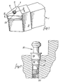
- the present invention consists of a toolholder 1 for holding a cutting insert 3.
- the cutting insert may be a negative rake insert, as shown in Figure 1, a positive rake cutting insert, or any of the other insert styles known in the art.
- the toolholder 1 comprises a toolholder body 5 and a locking pin 7.
- the locking pin 7 has a head portion 23 which fits into a tapered aperture 6 in the cutting insert 3 and clamps against a side wall of that tapered aperture so as to hold the cutting insert 3 on an insert seat on the toolholder body 5.
- a toolholder body 5 having an insert receiving pocket 11.
- the insert receiving pocket 11 has a side wall 13 rising up from a bottom wall 15.
- a pin receiving hole 17 is aligned normally to the bottom wall 1 5.
- This pin receiving hole 17 has a smooth bore section 21 and a threaded section 19.
- the locking pin 7 has an upper portion 23 which has a first and a second diameter with the first diameter being smaller than the second diameter. Formed between the first and second diameter is a downwardly facing shoulder 25 which will be used to abut against a tapered aperture 6 in the insert 3. The second diameter is sized so as to fit within a reduced diameter portion 4 of the insert aperture.
- a threaded section 27 At the other end of the locking pin 7 is a threaded section 27. This threaded section has reduced pitch diameter threads on it. Located between the upper portion 23 and the threaded section 27 is an increased diameter section 29. As can be seen in this figure, a flange 33 may be located near the top of the increased diameter section 29 when a shim member 31 is used for mounting the insert 3.
- the longitudinal axis, or a center line of the pin is held parallel to the axis I-I of the cutting insert aperture 6.
- the axis P-P of the locking pin 7 and the axis I-I of the cutting insert 3 are not colinear, the axis P-P of the locking pin 7 being closer to the side wall 13 than the axis I-I of the cutting insert.
- the downwardly facing shoulder 25 of the upper portion of the pin 23 acts to loosely hold captive the cutting insert 3.
- the locking pin 7 maintains its parallel relationship to the axis of the cutting insert and the axis of the pin receiving hole 17 during the clamping of the insert 3 into the insert receiving pocket 11.
- the locking pin 7 may have hex shaped openings 8, or equivalents, at both ends of the pin 7 for engagement with a suitable rotation causing means.
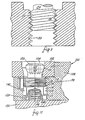
- Figure 5 shows a preferred embodiment of the toolholder body and locking pin.
- Locking pin 52 is shown having an increased diameter section which is composed of two steps 54 and 60.
- Step 54 fits slidingly and snugly into a smooth bore 56 in the pin receiving hole 55 and step 60 fits snugly and slidingly into a smooth bore 58 in the pin receiving hole 55.
- Step 60 has a smaller diameter than step 54 and is located between step 54 and the threaded section on the end of the locking pin.
- the purpose of forming the increased diameter section, as shown in Figure 5, is to improve the load bearing characteristics of the pin when the pin is clamped against the cutting insert.
- Locking pin 52 when clamped against an insert, will bear the loads produced by the clamping in two areas diametrically opposite to where the pin clamps against the insert; one area on each of steps 54 and 60, rather than the one bearing area produced in the locking pin 7 increased diameter section 29.
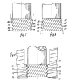
- Figure 6 shows a longitudinal diametric cross section of the threaded section of the locking pin shown in Figures 2 through 5. It can be seen that the threaded section is made up of individual thread members having peaks 72. The peaks have been turned down on a lathe such that they form an imaginary envelope that appears to be bi-convex as shown in Figure 6.
- This shaping of the threads allows the locking pin 7 to easily tilt in the threaded section 19 of the pin receiving hole 17 when the locking pin 7 is positioned as shown in Figure 2, while also allowing each thread to be engaged against the threads in threaded section 19, thereby distributing the"vertical clamping load produced on the threads when the insert is clamped as shown in Figure 4.
- the reduced pitch diameter threads can have the shapes shown in Figures 7 and 8.
- FIG. 9 Shown in Figure 9 is another alternative embodiment according to the present invention in which the threaded section 150 of a pin receiving hole has an increased pitch diameter threaded section 152.
- This embodiment would allow the use of a locking pin 154 having a standard uniformly threaded section 156 in the present invention. When threaded section 156 is engaged with the increased pitch diameter threaded section 152, the pin 154 would be tiltable.
- Figure 10 shows an alternative embodiment to the toolholders and locking pins shown in the previous figures.
- a toolholder 100 having a toolholder body 108 with an insert receiving pocket having a side wall 110 rising from the bottom wall 112.
- the bottom wall 112 has a pin receiving hole 114 formed downwardly and substantially perpendicular to it.
- This insert receiving hole 114 has a threaded section 116 and a smooth bore section 118.
- a locking pin 120 Located in this pin receiving hole 114 is a locking pin 120.
- the locking pin has an upper portion 122 with a downwardly facing shoulder 124.
- an increased diameter section 126 At the lower end of the locking pin 120 is an increased diameter section 126.
- increased diameter section 126 When viewed in profile, increased diameter section 126 has an outer peripheral surface 128 that tapers inwardly as it extends outwardly.
- a threaded section 130 Located between the upper portion 122 and the increased diameter section 126 is a threaded section 130.
- the locking pin 120 clamps downwardly against a tapered upwardly facing wall 106 in an insert aperture 104 so as to clamp the insert 102 against the side wall 110 and the bottom wall 112 of the insert receiving pocket.
- This locking pin 120 can be formed in a shorter length than the locking pin shown in Figures 2 through 8, and is, therefore, ideally suited for toolholder bodies 108 which are required to have a shallow depth.
- toolholder bodies 108 having a short depth may be required on the periphery of a boring head 150.
- the toolholder 100 operates as follows: When the threaded section 130 of the locking pin 120 is out of engagement with the threaded section 116 of the pin receiving hole 114, the pin 120 is able to tilt outwardly since the increased diameter section 126 has a tapered peripheral surface 128. At this point, the upwardly facing shoulder 129 of the increased diameter section 126 may abut a downwardly facing shoulder 144 in the pin receiving hole 114. It may also abut an abutment surface or pin 140 which protrudes into the smooth bore section 118 of the pin receiving hole 114. Abutment pin 140 is optional and, when used in conjunction with spring 148 in recess 146, serves to automatically tilt the pin 120 outwardly away from wall 110.
- the cutting insert 102 may be slid over the upper portion 122 of the locking pin 120.
- the locking pin is then rotated so as to threadedly engage the threaded section 116 of the pin receiving hole 114 and thereby becomes aligned parallel to the axis of the pin receiving hole 114 and is no longer tiltable.
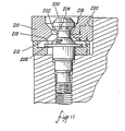
- Figure 11 shows another embodiment of the present invention.
- pin 200 is equivalent to the pin 52 shown in Figure 5 with the exception that the neck portion 202 between the downwardly facing clamping shoulder 204 and the shim retaining flange 206 has been strengthened by a frustoconical section 208 tapering upwardly.
- pin 200 is preferably used with an insert 210 whose central bore diameter gradually increases as it approaches the bottom face 212 of the insert 210.
- the apex angle of the conical envelope in which the insert tapered surface 218 lies is preferably equal to or greater than the apex angle for the frustoconical surface 208 on the pin 200.
- the distance A, between the upper end of the tapered section 218 in the insert bore and the upper end of the frustoconical section 208 be greater than the distance B, between the upper face 216 of the flange 206 and the bottom face 212 of the insert.
Landscapes
- Engineering & Computer Science (AREA)
- Mechanical Engineering (AREA)
- Cutting Tools, Boring Holders, And Turrets (AREA)
- Control And Other Processes For Unpacking Of Materials (AREA)
- Food-Manufacturing Devices (AREA)
- Transition And Organic Metals Composition Catalysts For Addition Polymerization (AREA)
Priority Applications (1)
| Application Number | Priority Date | Filing Date | Title |
|---|---|---|---|
| AT81108772T ATE10714T1 (de) | 1980-11-10 | 1981-10-23 | Schneideinsatzhalter, verfahren zum festhalten eines schneideinsatzes und befestigungsbolzen fuer einen schneideinsatz. |
Applications Claiming Priority (4)
| Application Number | Priority Date | Filing Date | Title |
|---|---|---|---|
| US06/205,440 US4397592A (en) | 1980-11-10 | 1980-11-10 | Insert holder and method of holding |
| US06/214,233 US4398853A (en) | 1980-11-10 | 1980-12-08 | Insert holder and method of holding |
| US214233 | 1980-12-08 | ||
| US205440 | 1998-12-04 |
Publications (3)
| Publication Number | Publication Date |
|---|---|
| EP0051775A2 EP0051775A2 (en) | 1982-05-19 |
| EP0051775A3 EP0051775A3 (en) | 1982-06-16 |
| EP0051775B1 true EP0051775B1 (en) | 1984-12-12 |
Family
ID=26900430
Family Applications (1)
| Application Number | Title | Priority Date | Filing Date |
|---|---|---|---|
| EP81108772A Expired EP0051775B1 (en) | 1980-11-10 | 1981-10-23 | Toolholder for use in holding a cutting insert, method of clamping a cutting insert and locking pin for securing a cutting insert |
Country Status (14)
| Country | Link |
|---|---|
| US (1) | US4398853A (da) |
| EP (1) | EP0051775B1 (da) |
| AU (1) | AU554465B2 (da) |
| CA (1) | CA1162724A (da) |
| DE (2) | DE51775T1 (da) |
| DK (1) | DK155355C (da) |
| ES (1) | ES506937A0 (da) |
| FI (1) | FI83172C (da) |
| IE (1) | IE52510B1 (da) |
| IL (1) | IL64194A (da) |
| MX (1) | MX153582A (da) |
| NO (1) | NO154218C (da) |
| NZ (1) | NZ198860A (da) |
| PT (1) | PT73956B (da) |
Families Citing this family (27)
| Publication number | Priority date | Publication date | Assignee | Title |
|---|---|---|---|---|
| US4615650A (en) * | 1985-10-15 | 1986-10-07 | Gte Valeron Corporation | Locking pin for a tool holder |
| JPS6450008U (da) * | 1987-09-24 | 1989-03-28 | ||
| DE68921089T2 (de) * | 1988-04-11 | 1995-06-08 | Seco Tools Ab | Schneidewerkzeug mit Doppelspannstiftanordnung. |
| US5004378A (en) * | 1988-05-19 | 1991-04-02 | Mitsubishi Metal Corporation | Clamped cutting tool |
| DE9203373U1 (de) * | 1992-03-13 | 1992-04-23 | Hartmetall-Werkzeugfabrik Paul Horn GmbH, 7400 Tübingen | Decolletage-Werkzeug |
| DE4325999C2 (de) * | 1993-08-03 | 1996-02-15 | Walter Ag | Rundlaufendes Schneidwerkzeug mit Wendeplattenbestückung, insbesondere zur Metallbearbeitung |
| SE508666C2 (sv) * | 1994-05-27 | 1998-10-26 | Sandvik Ab | Skärhållare för vändskärsplattor |
| SE505726C2 (sv) * | 1995-02-27 | 1997-10-06 | Sandvik Ab | Fastspänningsanordning för skärplattor |
| SE509594C2 (sv) * | 1996-01-26 | 1999-02-15 | Sandvik Ab | Indexering av vändskär |
| IL124282A (en) * | 1998-04-29 | 2001-10-31 | Iscar Ltd | Cutting tool assembly and a cutting insert for use therein |
| US6457914B1 (en) | 2000-08-24 | 2002-10-01 | Kennametal Inc. | Clamping tool holder |
| JP4639862B2 (ja) * | 2004-03-26 | 2011-02-23 | 三菱マテリアル株式会社 | スローアウェイチップのクランプ機構 |
| IL167179A (en) * | 2005-03-01 | 2009-07-20 | Iscar Ltd | A tool for removing scratches and cutting for it |
| US7261495B1 (en) * | 2006-02-21 | 2007-08-28 | Kennametal Inc. | Assembly for retaining a cutting insert in a pocket of a tool holder |
| CN101754828B (zh) * | 2007-06-06 | 2016-01-27 | 诺斯库有限公司 | 刀具架及其所用的刀头 |
| US7547163B2 (en) * | 2007-07-16 | 2009-06-16 | Kennametal Inc. | Clamping tool holder |
| WO2009028747A1 (en) * | 2007-08-30 | 2009-03-05 | Taegutec. Ltd. | Cutting tool with an inclined clamping screw |
| US8057131B2 (en) * | 2009-01-17 | 2011-11-15 | Kennametal Inc. | Clamping tool holder |
| AT11470U1 (de) * | 2009-06-10 | 2010-11-15 | Ceratizit Austria Gmbh | Schneidwerkzeug |
| WO2011071007A1 (ja) * | 2009-12-08 | 2011-06-16 | 株式会社タンガロイ | 刃先交換式切削工具 |
| CA2924757C (en) * | 2013-09-03 | 2018-12-04 | No Screw Ltd. | Mounting mechanism for a cutting insert, a cutting insert therefor and a cutting tool using said insert |
| AT14369U1 (de) * | 2014-11-24 | 2015-09-15 | Ceratizit Austria Gmbh | Werkzeug für die zerspanende Bearbeitung |
| EP3253517A1 (en) | 2015-02-04 | 2017-12-13 | No Screw Ltd. | Cutting tool comprising a cutting tool holder and a cutting insert therefor |
| EP3288701A1 (en) | 2015-04-30 | 2018-03-07 | No Screw Ltd. | Dynamic clamping mechanism |
| WO2017051714A1 (ja) * | 2015-09-24 | 2017-03-30 | 三菱日立ツール株式会社 | 刃先交換式切削工具 |
| EP3737541A4 (en) * | 2018-01-14 | 2021-09-15 | Craftstech, Inc. | MODULAR CUTTING BLADE AND MACHINES CONTAINER ASSEMBLY |
| EP3888826A1 (de) * | 2020-03-31 | 2021-10-06 | CERATIZIT Austria Gesellschaft m.b.H. | Zerspanungswerkzeug und verfahren zum indexieren eines schneideinsatzes |
Family Cites Families (18)
| Publication number | Priority date | Publication date | Assignee | Title |
|---|---|---|---|---|
| US2519938A (en) * | 1946-04-16 | 1950-08-22 | William L Sitton | Toolholder |
| GB976597A (en) * | 1962-10-10 | 1964-12-02 | Wickman Wimet Ltd | Tool holders for use with detachable inserts |
| US3192603A (en) * | 1964-02-06 | 1965-07-06 | Walter J Greenleaf | Cutting tool |
| DE1295967B (de) * | 1964-03-30 | 1969-05-22 | Devlieg Machine Co | Spanabhebendes Werkzeug mit auswechselbarem Schneidkoerper |
| US3341920A (en) * | 1965-02-16 | 1967-09-19 | Gen Electric | Cutting tool |
| US3284874A (en) * | 1965-11-22 | 1966-11-15 | De Vlieg Machine Co | Cutting tool with removal cutter element |
| GB1164322A (en) * | 1966-01-07 | 1969-09-17 | Hudson Arthur F | Improvements in or relating to Tool Holders. |
| SE324272B (da) * | 1968-09-24 | 1970-05-25 | Fagersta Bruks Ab | |
| US3546758A (en) * | 1968-10-02 | 1970-12-15 | Howmet Corp | Cutting tools |
| US3654682A (en) * | 1970-09-01 | 1972-04-11 | Edward H Newbould | Tool holder |
| DE2226188A1 (de) * | 1971-06-03 | 1973-02-01 | Werner Keller | Klemmhalter zum festlegen eines schneidplaettchens |
| CH545156A (fr) * | 1971-11-23 | 1974-01-31 | Stellram Sa | Dispositif de fixation d'une plaquette de coupe en métal dur sur un support |
| DE2414755A1 (de) * | 1974-03-27 | 1975-10-09 | Iscar Ltd | Schneidwerkzeughalter |
| SU517406A1 (ru) * | 1974-08-16 | 1976-06-15 | Всесоюзный Научно-Исследовательский Инструментальный Институт | Сборный режущий инструмент |
| SU561626A1 (ru) * | 1975-05-26 | 1977-06-15 | Проектно-Конструкторский Технологический Институт | Режущий инструмент |
| SU543465A1 (ru) * | 1975-08-07 | 1977-01-25 | Всесоюзный Научно-Исследовательский Инструментальный Институт | Сборный режущий инструмент |
| DE2720249A1 (de) * | 1977-05-05 | 1978-11-16 | Pietro Guglielmetti | Verbesserungen an buegelaufspannungen einer schneidplatte auf einem werkzeugschaft |
| SU665993A1 (ru) * | 1978-01-10 | 1979-06-05 | Сестрорецкий Инструментальный Завод Им. Воскова | Режущий инструмент |
-
1980
- 1980-12-08 US US06/214,233 patent/US4398853A/en not_active Expired - Lifetime
-
1981
- 1981-10-20 CA CA000388321A patent/CA1162724A/en not_active Expired
- 1981-10-23 EP EP81108772A patent/EP0051775B1/en not_active Expired
- 1981-10-23 DE DE198181108772T patent/DE51775T1/de active Pending
- 1981-10-23 DE DE8181108772T patent/DE3167743D1/de not_active Expired
- 1981-11-02 IL IL8164194A patent/IL64194A/xx not_active IP Right Cessation
- 1981-11-03 NZ NZ198860A patent/NZ198860A/en unknown
- 1981-11-05 AU AU77143/81A patent/AU554465B2/en not_active Ceased
- 1981-11-06 ES ES506937A patent/ES506937A0/es active Granted
- 1981-11-09 FI FI813520A patent/FI83172C/fi not_active IP Right Cessation
- 1981-11-09 DK DK494181A patent/DK155355C/da not_active IP Right Cessation
- 1981-11-09 NO NO813788A patent/NO154218C/no unknown
- 1981-11-09 PT PT73956A patent/PT73956B/pt unknown
- 1981-11-09 IE IE2612/81A patent/IE52510B1/en unknown
- 1981-11-09 MX MX190024A patent/MX153582A/es unknown
Also Published As
| Publication number | Publication date |
|---|---|
| PT73956A (en) | 1981-12-01 |
| ES8302503A1 (es) | 1983-02-01 |
| DK494181A (da) | 1982-05-11 |
| NO813788L (no) | 1982-05-11 |
| EP0051775A3 (en) | 1982-06-16 |
| MX153582A (es) | 1986-11-21 |
| DK155355C (da) | 1989-08-21 |
| DE51775T1 (de) | 1983-01-05 |
| AU7714381A (en) | 1982-05-20 |
| FI813520L (fi) | 1982-05-11 |
| IE812612L (en) | 1982-05-10 |
| FI83172B (fi) | 1991-02-28 |
| PT73956B (en) | 1983-02-18 |
| FI83172C (fi) | 1991-06-10 |
| AU554465B2 (en) | 1986-08-21 |
| NO154218B (no) | 1986-05-05 |
| US4398853A (en) | 1983-08-16 |
| ES506937A0 (es) | 1983-02-01 |
| DK155355B (da) | 1989-04-03 |
| DE3167743D1 (en) | 1985-01-24 |
| IL64194A (en) | 1985-09-29 |
| NO154218C (no) | 1986-08-20 |
| NZ198860A (en) | 1984-10-19 |
| CA1162724A (en) | 1984-02-28 |
| IL64194A0 (en) | 1982-02-28 |
| IE52510B1 (en) | 1987-11-25 |
| EP0051775A2 (en) | 1982-05-19 |
Similar Documents
| Publication | Publication Date | Title |
|---|---|---|
| EP0051775B1 (en) | Toolholder for use in holding a cutting insert, method of clamping a cutting insert and locking pin for securing a cutting insert | |
| EP0342692B1 (en) | Cutting tool | |
| EP0876235B1 (en) | Cutting tool and cutting insert | |
| US4397592A (en) | Insert holder and method of holding | |
| EP0833713B1 (en) | Cutting tool and method | |
| EP1401603B2 (en) | Sintered cutting insert having center hole for clamp screw | |
| US3662444A (en) | Indexable cutting insert and holder therefor | |
| US5236288A (en) | Cutter with positively locked round inserts | |
| US4248555A (en) | Drill assembly | |
| US3740807A (en) | Inserted blade cutting tool with locking pin | |
| EP0912280B1 (en) | A cutting tool for chip removal and a locking pin | |
| US3913197A (en) | Positive lock insert | |
| US6033158A (en) | Small-shank tool for automatic lathes | |
| US4875812A (en) | Cutting tool employing a double pin retention assembly | |
| US4861048A (en) | Jaw assembly for lathe chuck | |
| US3864799A (en) | Tool holder | |
| US4525109A (en) | Cutting tool having a cutting blade in a shank slot | |
| US4226560A (en) | Toolholder anvil seat for indexable inserts | |
| EP0638385A1 (en) | Cutting tool | |
| JP2001138119A (ja) | 切削工具及びスローアウェイセンタドリル | |
| US5201613A (en) | Single point adjustable cutting insert holder | |
| EP0337970B1 (en) | Cutting tool employing a double pin retention assembly | |
| US5921719A (en) | Insert holder with top clamp | |
| US4511293A (en) | Insert cutter | |
| NZ208715A (en) | Toolholder for mounting cutting inserts |
Legal Events
| Date | Code | Title | Description |
|---|---|---|---|
| PUAI | Public reference made under article 153(3) epc to a published international application that has entered the european phase |
Free format text: ORIGINAL CODE: 0009012 |
|
| PUAL | Search report despatched |
Free format text: ORIGINAL CODE: 0009013 |
|
| AK | Designated contracting states |
Designated state(s): AT BE CH DE FR GB IT LU NL SE |
|
| AK | Designated contracting states |
Designated state(s): AT BE CH DE FR GB IT LU NL SE |
|
| TCAT | At: translation of patent claims filed | ||
| ITCL | It: translation for ep claims filed |
Representative=s name: STUDIO TORTA SOCIETA' SEMPLICE |
|
| TCNL | Nl: translation of patent claims filed | ||
| 17P | Request for examination filed |
Effective date: 19820914 |
|
| DET | De: translation of patent claims | ||
| ITF | It: translation for a ep patent filed | ||
| GRAA | (expected) grant |
Free format text: ORIGINAL CODE: 0009210 |
|
| AK | Designated contracting states |
Designated state(s): AT BE CH DE FR GB IT LI LU NL SE |
|
| REF | Corresponds to: |
Ref document number: 10714 Country of ref document: AT Date of ref document: 19841215 Kind code of ref document: T |
|
| REF | Corresponds to: |
Ref document number: 3167743 Country of ref document: DE Date of ref document: 19850124 |
|
| ET | Fr: translation filed | ||
| PLBE | No opposition filed within time limit |
Free format text: ORIGINAL CODE: 0009261 |
|
| STAA | Information on the status of an ep patent application or granted ep patent |
Free format text: STATUS: NO OPPOSITION FILED WITHIN TIME LIMIT |
|
| PG25 | Lapsed in a contracting state [announced via postgrant information from national office to epo] |
Ref country code: LU Free format text: LAPSE BECAUSE OF NON-PAYMENT OF DUE FEES Effective date: 19851031 |
|
| 26N | No opposition filed | ||
| PGFP | Annual fee paid to national office [announced via postgrant information from national office to epo] |
Ref country code: LU Payment date: 19901016 Year of fee payment: 10 |
|
| EPTA | Lu: last paid annual fee | ||
| PGFP | Annual fee paid to national office [announced via postgrant information from national office to epo] |
Ref country code: GB Payment date: 19910926 Year of fee payment: 11 |
|
| PGFP | Annual fee paid to national office [announced via postgrant information from national office to epo] |
Ref country code: AT Payment date: 19910927 Year of fee payment: 11 |
|
| PGFP | Annual fee paid to national office [announced via postgrant information from national office to epo] |
Ref country code: SE Payment date: 19910930 Year of fee payment: 11 |
|
| PGFP | Annual fee paid to national office [announced via postgrant information from national office to epo] |
Ref country code: FR Payment date: 19911021 Year of fee payment: 11 |
|
| PGFP | Annual fee paid to national office [announced via postgrant information from national office to epo] |
Ref country code: DE Payment date: 19911030 Year of fee payment: 11 |
|
| ITTA | It: last paid annual fee | ||
| PGFP | Annual fee paid to national office [announced via postgrant information from national office to epo] |
Ref country code: NL Payment date: 19911031 Year of fee payment: 11 |
|
| PGFP | Annual fee paid to national office [announced via postgrant information from national office to epo] |
Ref country code: BE Payment date: 19911113 Year of fee payment: 11 |
|
| PGFP | Annual fee paid to national office [announced via postgrant information from national office to epo] |
Ref country code: CH Payment date: 19920113 Year of fee payment: 11 |
|
| PG25 | Lapsed in a contracting state [announced via postgrant information from national office to epo] |
Ref country code: GB Effective date: 19921023 Ref country code: AT Effective date: 19921023 |
|
| PG25 | Lapsed in a contracting state [announced via postgrant information from national office to epo] |
Ref country code: SE Effective date: 19921024 |
|
| PG25 | Lapsed in a contracting state [announced via postgrant information from national office to epo] |
Ref country code: LI Effective date: 19921031 Ref country code: CH Effective date: 19921031 Ref country code: BE Effective date: 19921031 |
|
| BERE | Be: lapsed |
Owner name: KENNAMETAL INC. Effective date: 19921031 |
|
| PG25 | Lapsed in a contracting state [announced via postgrant information from national office to epo] |
Ref country code: NL Effective date: 19930501 |
|
| NLV4 | Nl: lapsed or anulled due to non-payment of the annual fee | ||
| GBPC | Gb: european patent ceased through non-payment of renewal fee |
Effective date: 19921023 |
|
| PG25 | Lapsed in a contracting state [announced via postgrant information from national office to epo] |
Ref country code: FR Effective date: 19930630 |
|
| REG | Reference to a national code |
Ref country code: CH Ref legal event code: PL |
|
| PG25 | Lapsed in a contracting state [announced via postgrant information from national office to epo] |
Ref country code: DE Effective date: 19930701 |
|
| REG | Reference to a national code |
Ref country code: FR Ref legal event code: ST |
|
| EUG | Se: european patent has lapsed |
Ref document number: 81108772.5 Effective date: 19930510 |