EP0051477A1 - Procédé et appareil de commande d'orientation de broche - Google Patents
Procédé et appareil de commande d'orientation de broche Download PDFInfo
- Publication number
- EP0051477A1 EP0051477A1 EP81305194A EP81305194A EP0051477A1 EP 0051477 A1 EP0051477 A1 EP 0051477A1 EP 81305194 A EP81305194 A EP 81305194A EP 81305194 A EP81305194 A EP 81305194A EP 0051477 A1 EP0051477 A1 EP 0051477A1
- Authority
- EP
- European Patent Office
- Prior art keywords
- spindle
- speed
- signal
- control circuit
- stopping
- Prior art date
- Legal status (The legal status is an assumption and is not a legal conclusion. Google has not performed a legal analysis and makes no representation as to the accuracy of the status listed.)
- Granted
Links
- 230000022233 establishment of spindle orientation Effects 0.000 title claims abstract description 18
- 238000000034 method Methods 0.000 title claims description 8
- 238000013459 approach Methods 0.000 claims description 9
- 238000012937 correction Methods 0.000 claims description 4
- 230000001960 triggered effect Effects 0.000 abstract description 2
- 238000010586 diagram Methods 0.000 description 10
- 230000007246 mechanism Effects 0.000 description 7
- 238000003754 machining Methods 0.000 description 4
- 230000004044 response Effects 0.000 description 4
- 230000000630 rising effect Effects 0.000 description 3
- 230000008859 change Effects 0.000 description 2
- 239000013256 coordination polymer Substances 0.000 description 2
- 230000007423 decrease Effects 0.000 description 2
- 230000003247 decreasing effect Effects 0.000 description 1
- 230000000694 effects Effects 0.000 description 1
- 238000010304 firing Methods 0.000 description 1
- 238000003780 insertion Methods 0.000 description 1
- 230000037431 insertion Effects 0.000 description 1
- 238000007689 inspection Methods 0.000 description 1
- 238000012423 maintenance Methods 0.000 description 1
- 230000007257 malfunction Effects 0.000 description 1
- 238000012986 modification Methods 0.000 description 1
- 230000004048 modification Effects 0.000 description 1
- 230000032258 transport Effects 0.000 description 1
Images


Classifications
-
- G—PHYSICS
- G05—CONTROLLING; REGULATING
- G05B—CONTROL OR REGULATING SYSTEMS IN GENERAL; FUNCTIONAL ELEMENTS OF SUCH SYSTEMS; MONITORING OR TESTING ARRANGEMENTS FOR SUCH SYSTEMS OR ELEMENTS
- G05B19/00—Programme-control systems
- G05B19/02—Programme-control systems electric
- G05B19/18—Numerical control [NC], i.e. automatically operating machines, in particular machine tools, e.g. in a manufacturing environment, so as to execute positioning, movement or co-ordinated operations by means of programme data in numerical form
- G05B19/19—Numerical control [NC], i.e. automatically operating machines, in particular machine tools, e.g. in a manufacturing environment, so as to execute positioning, movement or co-ordinated operations by means of programme data in numerical form characterised by positioning or contouring control systems, e.g. to control position from one programmed point to another or to control movement along a programmed continuous path
- G05B19/21—Numerical control [NC], i.e. automatically operating machines, in particular machine tools, e.g. in a manufacturing environment, so as to execute positioning, movement or co-ordinated operations by means of programme data in numerical form characterised by positioning or contouring control systems, e.g. to control position from one programmed point to another or to control movement along a programmed continuous path using an incremental digital measuring device
- G05B19/23—Numerical control [NC], i.e. automatically operating machines, in particular machine tools, e.g. in a manufacturing environment, so as to execute positioning, movement or co-ordinated operations by means of programme data in numerical form characterised by positioning or contouring control systems, e.g. to control position from one programmed point to another or to control movement along a programmed continuous path using an incremental digital measuring device for point-to-point control
- G05B19/231—Numerical control [NC], i.e. automatically operating machines, in particular machine tools, e.g. in a manufacturing environment, so as to execute positioning, movement or co-ordinated operations by means of programme data in numerical form characterised by positioning or contouring control systems, e.g. to control position from one programmed point to another or to control movement along a programmed continuous path using an incremental digital measuring device for point-to-point control the positional error is used to control continuously the servomotor according to its magnitude
- G05B19/232—Numerical control [NC], i.e. automatically operating machines, in particular machine tools, e.g. in a manufacturing environment, so as to execute positioning, movement or co-ordinated operations by means of programme data in numerical form characterised by positioning or contouring control systems, e.g. to control position from one programmed point to another or to control movement along a programmed continuous path using an incremental digital measuring device for point-to-point control the positional error is used to control continuously the servomotor according to its magnitude with speed feedback only
-
- G—PHYSICS
- G05—CONTROLLING; REGULATING
- G05B—CONTROL OR REGULATING SYSTEMS IN GENERAL; FUNCTIONAL ELEMENTS OF SUCH SYSTEMS; MONITORING OR TESTING ARRANGEMENTS FOR SUCH SYSTEMS OR ELEMENTS
- G05B19/00—Programme-control systems
- G05B19/02—Programme-control systems electric
- G05B19/18—Numerical control [NC], i.e. automatically operating machines, in particular machine tools, e.g. in a manufacturing environment, so as to execute positioning, movement or co-ordinated operations by means of programme data in numerical form
- G05B19/19—Numerical control [NC], i.e. automatically operating machines, in particular machine tools, e.g. in a manufacturing environment, so as to execute positioning, movement or co-ordinated operations by means of programme data in numerical form characterised by positioning or contouring control systems, e.g. to control position from one programmed point to another or to control movement along a programmed continuous path
- G05B19/39—Numerical control [NC], i.e. automatically operating machines, in particular machine tools, e.g. in a manufacturing environment, so as to execute positioning, movement or co-ordinated operations by means of programme data in numerical form characterised by positioning or contouring control systems, e.g. to control position from one programmed point to another or to control movement along a programmed continuous path using a combination of the means covered by at least two of the preceding groups G05B19/21, G05B19/27 and G05B19/33
-
- G—PHYSICS
- G05—CONTROLLING; REGULATING
- G05B—CONTROL OR REGULATING SYSTEMS IN GENERAL; FUNCTIONAL ELEMENTS OF SUCH SYSTEMS; MONITORING OR TESTING ARRANGEMENTS FOR SUCH SYSTEMS OR ELEMENTS
- G05B2219/00—Program-control systems
- G05B2219/30—Nc systems
- G05B2219/49—Nc machine tool, till multiple
- G05B2219/49273—Switch between continuous drive and index or stop mode
Definitions
- This invention relates to a spindle orientation method and apparatus control / and, more particularly, to a spindle orien- method and apparatus tation control / capable of rotating the spindle of a machine tool at a commanded speed, and of stopping the spindle at a commanded angular position with a high accuracy.
- Machine tools with an automatic tool change function are well known in the art. These are machine tools that perform machining work automatically while various tools are changed, also automatically.
- boring-type machine tools in order to insert a boring rod into a hole a previously drilled in,/workpiece.
- the need to stop a specified portion of a spindle at a predetermined angular position or orientation in accurate fashion is quite common in mechanical machining operations.
- Fig. 1 is a block diagram showing a servo system employed in spindle rotation control
- Fig. 2 is an illustrative view useful in describing spindle orientation
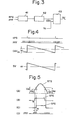
- Fig. 3 is a block diagram of a circuit for generating a position deviation signal
- Fig.4 is a waveform diagram of signals associated with the circuit of Fig. 3.
- a speed control circuit 1 a DC motor 2, a tachometer generator 3 for generating a voltage in accordance with the rotational speed of the DC motor 2, and an orientation control circuit 4 for producing a voltage in accordance with a deviation between a commanded stopping position and the actual position of a spindle7.
- Numeral 5 denotes a tool mounted on a spindle mechanism 6.
- the spindle 7 of the spindle mechanism is coupled to the DC motor 2 via a belt 8, although gears may also be used for this purpose.
- a 9 position coder,/or a pulse coder such as a rotary encoder adapted to generate a pulse whenever the spindle 7 rotates by a predetermined angle, is connected directly to the spindle 7.
- Numeral 10 denotes a changeover switch.
- numeral 11 denotes an orientation portion provided on the spindle 7. A tool change cannot be performed smoothly unless the orientation portion 11 comes to rest at a predetermined angular position when the spindle 7 is stopped.
- the speed control circuit 1 receives a command speed signal CV from a command speed signal generating circuit, which is not shown.
- the speed control circuit 1 also receives from the tachometer generator 3 an analog voltage AV which corresponds to the actual speed of the spindle.
- the speed control circuit 1 is operable to produce an analog voltage which corresponds to the deviation between the command speed signal CV (an analog voltage) and the actual speed signal AV which, as mentioned above, is an analog voltage.
- the speed control circuit 1 applies the analog deviation voltage to the DC motor 2 to rotate the motor at the com- manded speed.
- the speed control circuit 1, DC motor 2, tachometer generator 3 and a feedback line FL form a speed control feedback loop which functions to rotate the DC motor 2 at the commanded speed.
- the command speed signal CV is changed over to a value such as zero volt, and the speed of the motor 2 is reduced while applying an electrical brake thereto. Then, immediately before the motor 2 comes to rest, namely at such time that the speed has reached a fairly low level, an orientation command ORCM is applied to the changeover switch 10, so that the movable member of the switch is changed over from the contact a to the contact b.
- the orientation control circuit 4 is adapted to produce a rotational position deviation signal RPD, which is an analog voltage, in accordance with the deviation between a commanded stopping position which has been predetermined, and the actual angular position (orientation) of the spindle.
- RPD rotational position deviation signal
- Figs. 3 and 4 describe the operation of the orientation control circuit 4 for a case where there is but one stopping position for the orientation portion 11 on the spindle 7.
- the arrangement is such that the position coder 9 produces a one-revolution pulse RPS for each revolution of the spindle 7, and position pulses PPF each one of which is produced whenever the spindle rotates by a predetermined angle, the position coder 9 generating a total of N of these pulses PP for each single revolution of the spindle 7.
- the position coder 9 is attached to the spindle 7 in such a manner that it issues the one-revolution pulse RPS at such time that the orientation portion 11 on the spindle has rotated 180° from the commanded stopping position STP, shown in Fig. 2.
- a counter 41 shown in Fig. 3 is preset to the numerical value N upon the generation of the pulse RPS, and then has this preset value counted down by each position pulse PP that subsequently arrives from the position coder 9.
- a digital-to- analog converter (referred to as a DA converter hereinafter) 42converts the output of counter 41 (which output signal represents the content of the counter) into an analog signal DA V which is applied to an analog subtractor 43, the latter producing a difference voltage SV between the analog voltage DAV and a constant voltage V.
- the difference signal SV will have a sawtooth waveform that crosses the zero level at such time that 180° has been covered by the spindle from the point at which the one-revolution pulse RPS is generated, as shown in Fig. 4. Since the commanded stopping position of the spindle is displaced by exactly 180° from the point at which the pulse RPS is generated, as described above, the orientation portion 11 on the spindle 7 reaches the commanded stopping position at the moment the difference voltage SV crosses the zero level. It should be noted that the difference voltage SV is proportional to the rotational position deviation signal RPD.
- the speed control circuit 1 delivers a difference voltage between the rotational position deviation signal RPD and the actual speed signal AV, whereby positional servo control is executed to make the rotational position deviation signal RPD approach zero.
- the speed control circuit 1, DC motor 2, spindle 7, position coder 9, orientation control circuit 4 and changeover switch 10 form a position control feedback loop.
- Fig. 5 is a waveform diagram which is useful in describing the shift in the spindle stopping position.
- the position coder 9 produces the one-revolution signal RTS each time the spindle makes one complete revolution. Since the signal RTS has a sinusoidal shape, as shown in Fig. 5(A) it is converted into a one-revolution pulse RPS having the shape of a rectangular wave upon comparison with-a predetermined slicing level.
- the slicing circuit is set in such a manner that the slicing level when the signal RTS is rising differs from the slicing level when the signal RTS is decaying.
- the slicing circuit is furnished with a hysteresis characteristic.
- V NU represent the slicing level when the signal RTS is rising
- V ND represent the slicing level when signal RTS is decaying
- V RU denote the slicing level when RTS is rising
- V RD denote the slicing level when RTS is decaying, where V RU ⁇ V RD .
- the one-revolution pulse RPS therefore will appear as shown in Fig. 5(B) when the spindle is rotating in the forward direction, and as shown in Fig.
- the position of the rectangular pulse during forward rotation differs from that during reverse rotation.
- This shift in position corresponds to more than one of the position pulses PPF, as shown in Fig. 5(D).
- the instant at which the numerical value N is preset in counter 41 is the moment t N at which pulse RTP (Fig. 5(B)) rises during forward rotation, or the moment t R at which pulse RTP (Fig. 5(C)) decays during reverse rotation. Consequently, the position at which the value N is preset, and which is calculated in terms of the position pulses PPF, differs by more than one pulse, so that the spindle stopping-position is not the same for forward and reverse rotation. This obviously makes it impossible to stop the spindle at the commanded position with a high accuracy.
- an object of the present invention is method and apparatus to provide a spindle orientation control / which enable the spindle of a machine tool to be rotated at a commanded speed, and to be stopped at a commanded angular position with a high accuracy.
- Another object of the present invention is to pro- method and apparatus vide a spindle orientation control / which enable the spindle of a machine tool to be rotated at a commanded correctly speed, and to be stopped/at a commanded angular position regardless of whether the spindle is being driven in the forward or reverse direction.
- an apparatus for controlling the orientation of a spindle driven by a motor which apparatus comprises:
- a method of controlling the orientation of a spindle which comprises the steps of:
- the first object may be attained in at least one embodiment by providing a speed control circuit and a position control circuit, wherein the spindle drive motor is controlled in a speed control mode when the spindle is to be rotated at a commanded speed, and is switched over to a position control mode when the spindle is to be stopped at a commanded position, with the positional control operation being effected by pulse control.
- the second object may be attained by changing a preset value in accordance with whether the spindle is rotating in the forward or reverse direction, the value being preset in a counter contained in a position control circuit which is controlled by generated pulses in a position control mode. Changing the preset value makes it possible to compensate for an error in the spindle stopping position that results from a difference in the position of the leading or trailing edge of the one-revolution pulse generated for each single revolution of the spindle, said difference arising because the position of the leading or trailing edge of the one-revolution pulse varies depending upon the direction of spindle rotation.
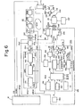
- a spindle 101 holding a workpiece 103 is driven by a spindle motor 102 coupled to the spindle 101 by a belt 106.
- a tachogenerator 104 mounted on the shaft of the spindle motor 102, is adapted to generate an actual speed signal AV of a voltage in accordance with the actual speed of the spindle motor 102.
- a pulse coder 105 such as a rotary encoder, or a position coder, is coupled to the spindle 101 by a belt 106' and generates a position pulse PPF whenever the spindle 101 rotates by a predetermined angle, and a one-revolution signal RTS whenever the spindle completes one revolution.
- a clamping mechanism'107 clamps the spindle 101 against movement at the end of a spindle orientation operation.
- a tool magazine 108 holds a rotary tool 109 and a-turning cutter 110 for lathe work.
- An X-axis drive motor 111 coupled to the tool magazine 108 via a belt 106", transports the desired tool along the X-axis under the control of a numerical control device 112.
- the latter device referred to also as an NC device, produces a spindle orientation command ORCM, a spindle rotational speed command VCMD, a drive signal XS for driving the motor 111, and a variety of other signals.
- a well-known speed control circuit shown at numeral 121, includes an adder 121a for producing a speed error voltage which is the difference between the rotational speed command VCMD and the actual speed AV of the spindle motor 102, this operation being performed in a speed control mode, a well-known phase compensating circuit 121b, a phase control circuit 121C for controlling the firing timing of thyristors in accordance with the speed error voltage, and a thyristor circuit 121d, whose thyristors are controlled as described, for supplying the spindle motor 102 with a voltage corresponding to the speed error.
- the speed control circuit 121, tachogenerator 104 and a speed feedback line FL form a speed control loop SPF.
- a spindle orientation control circuit 131 includes a speed command circuit 131a which issues a spindle speed command OVCMD at the time of an orientation control operation, a position control circuit 131b for stopping the spindle at any desired orientation, a changeover switch 131c for delivering selectively, at the time of the orientation control operation, the spindle speed command OVCMD from the speed command circuit 131a, and a positional error signal PER from the position control circuit 131b, a gain changeover control device 131d for adjusting the speed gain in response to a clutch changeover signal CLC, and a switch 131e for externally setting, in the form of a 12-bit digital value, the spindle stopping position.
- a speed command circuit 131a which issues a spindle speed command OVCMD at the time of an orientation control operation
- a position control circuit 131b for stopping the spindle at any desired orientation
- a changeover switch 131c for delivering selectively, at the time of the orientation control operation, the spindle
- the switch 131e is employed to enter m-number of pulses corresponding to an angle of M degrees measured from the machine zero point MRP to the commanded spindle stopping position CP.
- RTSP in Fig. 7 denotes an angular position at which the one-revolution signal RTS is generated.
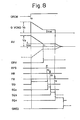
- the speed control circuit 131a includes an orientation speed sensing circuit 141 which generates, at the time of an orientation operation, a speed attainment signal ORV upon sensing that the spindle 101 has attained a predetermined speed V OR at which orientation is possible, a rotational direction sensing circuit 142 for producing a rotational direction signal RDS upon sensing the direction in which the spindle is rotating, and an orientation speed command circuit 143 for producing the speed command signal OVCMD at the time of an orientation operation.
- an orientation speed sensing circuit 141 which generates, at the time of an orientation operation, a speed attainment signal ORV upon sensing that the spindle 101 has attained a predetermined speed V OR at which orientation is possible
- a rotational direction sensing circuit 142 for producing a rotational direction signal RDS upon sensing the direction in which the spindle is rotating
- an orientation speed command circuit 143 for producing the speed command signal OVCMD at the time of an orientation operation.
- the position control circuit 131b includes a switch 151 for internally setting the spindle stopping position by digitally setting in the form of 12 bits the number of pulses n, equivalent to . 4096 (i.e., corresponding to the number of degrees N measured from the angular position RTSP to the zero point MRP in Fig.
- a register 152 in which a 12-bit digital value a (100...01 2049 in this embodiment) has been set, line receives 153, 154 which receive the position signal PP and the one-revolution signal RTS, respectively, generated by the pulse coder 105, a quadrupling circuit 155 which, since the position signal PP is composed of two sinusoidal waves displaced - in phase from each other by 7/ 2, is adapted to shape the sinusoidal waves into rectangular waves, to differentiate the rectangular waves, and to produce position pulses PPF in sync with the leading edges of the resulting signal, the frequency of position pulses PPF being four times the frequency of position signals PP, a slicing circuit 156 for producing the one-revolution pulse RPS, a 12-bit up-down counter 157 having a capacity equivalent to the 4096 position pulses PPF generated by the quadrupling circuit 155 when the spindle makes one full revolution, an up-down direction control circuit 158 for controlling the direction in which the up-down counter 157 counts, a DA
- a numerical value selection/arithmetic circuit 162 for selecting one of the numerical values a, m, n, c and for presetting the up-down counter 157 to the selected value, and'an AND gate 163 for producing an orientation end signal ORED.
- the sequence counter 161 delivers a first sequence state signal SQ 1 (logical "1") in response to the generation of the orientation command ORCM, as well as second, third and fourth sequence state signals SQ 2 , SQ3, SQ 4 (all logical "1") in response to the generation of the one-revolution pulse RPS, and to the generation of the signals HR (logical "1") and FR (logical "1"), respectively.
- the orientation speed sensing circuit 141 senses this speed and generates the speed attainment signal ORV (logical "1") at time t 1 .
- the speed command circuit 143 responds to the "1" logic by delivering a V OR output as the speed command OVCMD, also at time t 1 .
- the spundle 101 therefore continues to be rotated at the constant speed VOR.
- the generation of the pulse RPS sends the gate signal GM to logical "1" so that the numerical value -m which has been set in the externally set switch 131e is preset in the up-down counter 157 through the numerical value selection/arithmetic circuit 162.
- the spindle 101 continues to be rotated at the speed V OR .
- the quadrupling circuit 155 generates a single position pulse PPF each time the spindle 101 rotates by a predetermined amount, namely by 360°/4096.
- the position pulses PPF are counted up in the up-down counter 157. Whether the counter 157 counts the position pulses PPF up or down is determined by the up-down control circuit 158, as noted earlier.
- the pulses are counted up in the sequence states Q 2 , Q 3' and counted down in the sequence state Q 4 .
- the spindle 101 continues to rotate and, at time t 3 (position (3) in Fig. 9), has rotated through an angle of (B+M) degrees (equal to approximately 180° + M°) which corresponds to (b+m)-number of position pulses PPF. Therefore, at time t 3 , the content of the up-down counter 157 attains the value b, and the decoder responds by issuing the signal HR (logical "1"), whereby the third sequence state is attained (SQ 3 to logical "1").
- the gate signal GN goes to logical "1"
- the numerical value -n which has been set in the externally set switch 151 is preset in the up-down counter 157 through the numerical value selection/arithmetic circuit 162.
- the spindle 101 still continues to be rotated at the speed V OR , and at time t 4 (position (4) in Fig. 9) has rotated through an angle of N degrees, equivalent to n-number of position pulses. Therefore, at time t 4 , the content of the up-down counter 157 becomes zero, signal FR from decoder 160 goes to logical "1", and the fourth sequence state is attained.
- the changeover switch 131c responds to the "1" logic of signal FR by switching its contact from S 1 to S 21 thereby switching from the speed control to the position control mode.
- the numerical value a which has been set in the register 152 is preset in the counter 157 through the numerical value selection/arithmetic circuit 162.
- the value q is equivalent to the number of position pulses corresponding to about 180° of spindle rotation. Further, the speed command VCMD becomes zero at time t 4 .
- the DA converter 159 produces the positional error signal PER of a voltage proportional to the content of the up-down counter 157, and the spindle motor 102 continues to be rotated in the forward direction but at a speed which now corresponds to the signal PER.
- the content of the up-down counter 157 is counted down each time a position pulse PPF is generated, with the result that the output voltage of the DA converter 159 gradually decreases, the actual speed AV of the spindle motor 102 dminishing in accordance with the DA converter output.
- the spindle 101 following the generation of the one-revolution pulse RPS, is rotated by (B+ M ) degrees during the interval that SQ 2 is at logical "1", by N degrees during the interval that SQ 2 is at logical "1", by N degrees during the interval that SQ 3 is at logical "1", and by (360-B) degrees during the interval that SQ 4 is at logical "1".
- the spindle is stopped correctly at the commanded angular position or orientation after having been rotated by a total of 360 + (M+ N ) degrees.
- the numerical value selection/arithmetic circuit 162 responds to the.pulse RTP to select the values m and c, to perform the operation m-c, and to preset the result of this operation in up-down counter 162.
- the spindle continues rotating at the speed V OR and the up-down counter 162 counts up the position pulses PPF, with the content of the counter attaining the value b when the spindle reaches the position (3) after rotating by an angle of (B-M+C) degrees, which corresponds to (b-m+c)-number of position pulses PPF.
- the spindle 101 following the generation of the one-revolution pulse RPS, is rotated by (B-M+C) degrees during theinterval that SQ 2 is a "1", by (360-N) degrees during the interval that SQ 3 is a "1", and by [360-(B+C)] degrees during the interval that SQ 4 is a "1".
- the spindle is stopped correctly at the commanded angular position after having been rotated [720-(M+N)) degrees.
- Fig. 11 shows a case in which orientation is performed without correcting the stopping position when the spindle is rotating in the reverse direction.
- the orientation command ORCM is issued at exactly the same instant as in the case of Fig. 10. It can be appreciated that the stopping position is displaced by C degrees.
- the spindle stopping position is unchanged regardless of the direction of spindle rotation, even though a pulse coder is employed.
- the example thus assures that the spindle will always be stopped at the commanded positon with a high degree of accuracy.
- a spindle orientation control system having a speed control circuit (1) and a position control circuit (4) for rotating the spindle (7) of a machine tool at a commanded speed and for stopping the spindle (7) at a designated position with a high sccuracy, the speed control circuit (1) decelerating the spindle drive motor (6) on the basis of a spindle stopping command.
- a counter contained in the position control circuit (4) is triggered by a one-revolution pulse generated whenever the spindle (7) makes one full revolution, whereby the counter begins to count up position pulses each one of which is generated whenever the spindle rotates by a predetermined angle.
- operation shifts from the speed control mode to a position control mode, and said counter is preset to a number of pulses corresponding to the angle from the present position of the spindle to the desired stopping position.
- said pulse number is counted down by the position pulses and, at the same time, a voltage having a level which is proportional to the content of the counter is applied to the spindle drive motor (6), thereby reducing its rotational speed.
- the content of the counter reaches a value of zero, the spindle (7) is stopped at the predetermined position.
- Adjusting the value preset in the counter makes it possible to correct a spindle stopping position error that results from a difference in the position of the leading or trailing edge of the one revolution pulse, said difference arising because the position of the leading or trailing edge of the one-revolution pulse varies depending upon the direction of spindle rotation.
Landscapes
- Engineering & Computer Science (AREA)
- Human Computer Interaction (AREA)
- Manufacturing & Machinery (AREA)
- Physics & Mathematics (AREA)
- General Physics & Mathematics (AREA)
- Automation & Control Theory (AREA)
- Automatic Control Of Machine Tools (AREA)
- Control Of Position Or Direction (AREA)
- Stopping Of Electric Motors (AREA)
- Numerical Control (AREA)
Applications Claiming Priority (2)
| Application Number | Priority Date | Filing Date | Title |
|---|---|---|---|
| JP55152701A JPS6043261B2 (ja) | 1980-10-30 | 1980-10-30 | 主軸回転位置制御方式 |
| JP152701/80 | 1980-10-30 |
Publications (2)
| Publication Number | Publication Date |
|---|---|
| EP0051477A1 true EP0051477A1 (fr) | 1982-05-12 |
| EP0051477B1 EP0051477B1 (fr) | 1986-05-07 |
Family
ID=15546251
Family Applications (1)
| Application Number | Title | Priority Date | Filing Date |
|---|---|---|---|
| EP81305194A Expired EP0051477B1 (fr) | 1980-10-30 | 1981-10-30 | Procédé et appareil de commande d'orientation de broche |
Country Status (5)
| Country | Link |
|---|---|
| US (1) | US4398138A (fr) |
| EP (1) | EP0051477B1 (fr) |
| JP (1) | JPS6043261B2 (fr) |
| KR (1) | KR880000418B1 (fr) |
| DE (1) | DE3174576D1 (fr) |
Cited By (7)
| Publication number | Priority date | Publication date | Assignee | Title |
|---|---|---|---|---|
| DE3306555A1 (de) * | 1983-02-25 | 1984-08-30 | Brown, Boveri & Cie Ag, 6800 Mannheim | Regeleinrichtung fuer werkzeugmaschinen mit einer spindel |
| DE3310619A1 (de) * | 1983-03-24 | 1984-09-27 | Brown, Boveri & Cie Ag, 6800 Mannheim | Regeleinrichtung zur zielpositionierung bei werkzeugmaschinen mit einer spindel |
| EP0150216A1 (fr) * | 1983-06-13 | 1985-08-07 | Fanuc Ltd. | Procede de commande du gain d'une boucle de position |
| GB2158968A (en) * | 1984-05-18 | 1985-11-20 | Monarch Marking Systems Inc | Rotary knife control |
| WO1987003712A1 (fr) * | 1985-12-16 | 1987-06-18 | Delapena Honing Equipment Limited | Machine a pierrer |
| GB2184568A (en) * | 1985-11-06 | 1987-06-24 | Matsushita Electric Ind Co Ltd | Motor controller for a sewing machine |
| EP0369028A1 (fr) * | 1988-05-06 | 1990-05-23 | Kabushiki Kaisha Yaskawa Denki Seisakusho | Procede et dispositif de commande d'un robot a arbres rotatifs multiples |
Families Citing this family (26)
| Publication number | Priority date | Publication date | Assignee | Title |
|---|---|---|---|---|
| US4578748A (en) * | 1981-10-26 | 1986-03-25 | Kabushiki Kaisha Komatsu Seisakusho | Positioning control system |
| JPS58198198A (ja) * | 1982-05-13 | 1983-11-18 | Toshiba Corp | パルスモータ制御装置 |
| US4809425A (en) * | 1984-02-06 | 1989-03-07 | Monforte Robotics, Inc. | Adaptable, programmable production system |
| JPS6198186A (ja) * | 1984-10-17 | 1986-05-16 | Mitsubishi Electric Corp | インバ−タ装置の位置決め割り出し制御方式 |
| JPS61102454U (fr) * | 1984-12-07 | 1986-06-30 | ||
| JPS61214951A (ja) * | 1985-03-19 | 1986-09-24 | Hitachi Seiki Co Ltd | 工作機械の加工位置割出し装置 |
| JPH0773861B2 (ja) * | 1985-04-26 | 1995-08-09 | ファナック株式会社 | サーボモータで駆動される射出成形機の駆動制御方法 |
| JPS61296415A (ja) * | 1985-06-24 | 1986-12-27 | Mitsubishi Electric Corp | 主軸駆動用モ−タの位置決め制御装置 |
| JPS6320510A (ja) * | 1986-07-14 | 1988-01-28 | Fanuc Ltd | サ−ボモ−タの位置決め装置 |
| JP2819411B2 (ja) * | 1987-05-01 | 1998-10-30 | 三菱電機株式会社 | 定位置停止制御装置 |
| JP2770024B2 (ja) * | 1988-04-14 | 1998-06-25 | ファナック株式会社 | 自動制御工作機械用原点復帰装置 |
| JPH01264746A (ja) * | 1988-04-14 | 1989-10-23 | Fanuc Ltd | 自動制御工作機械用原点復帰装置 |
| JPH01270114A (ja) * | 1988-04-22 | 1989-10-27 | Fuji Electric Co Ltd | 回転体の位置決め制御用パルス発生器 |
| DE3823304A1 (de) * | 1988-07-09 | 1990-01-11 | Danfoss As | Verfahren und schaltung zur geschwindigkeitssteuerung eines durch einen antrieb bewegbaren objekts |
| JPH0261701A (ja) * | 1988-08-29 | 1990-03-01 | Fanuc Ltd | 数値制御装置 |
| JP2692274B2 (ja) * | 1989-06-22 | 1997-12-17 | 三菱電機株式会社 | 主軸位置・速度制御装置 |
| US5093610A (en) * | 1990-02-12 | 1992-03-03 | Abb Robotics Inc. | Apparatus for absolute position measurement |
| JPH07120217B2 (ja) * | 1990-08-16 | 1995-12-20 | 日本電気株式会社 | モータ制御回路 |
| DE4315637C2 (de) * | 1993-05-11 | 1996-12-19 | Brose Fahrzeugteile | Verfahren zur Erkennung der Position und der Bewegungsrichtung eines bewegbar gelagerten Teils |
| DE4343020C2 (de) * | 1993-12-16 | 1996-11-28 | Zinser Textilmaschinen Gmbh | Verfahren und Vorrichtung zur Steuerung der Bewegung eines Maschinenelements |
| GB9601753D0 (en) * | 1996-01-29 | 1996-03-27 | Switched Reluctance Drives Ltd | Dual mode position control systems with speed profiling |
| JP3579543B2 (ja) * | 1996-08-22 | 2004-10-20 | 東芝機械株式会社 | 位置制御システム |
| US7401710B2 (en) * | 2002-10-04 | 2008-07-22 | Dixie-Narco, Inc. | Vending machine dispensing system |
| JP5623757B2 (ja) * | 2010-02-23 | 2014-11-12 | 山洋電気株式会社 | モータの制御方法及び装置 |
| US9093933B2 (en) * | 2013-08-27 | 2015-07-28 | GM Global Technology Operations LLC | Method and apparatus for monitoring rotational position of an electric machine |
| JP2019042910A (ja) * | 2017-09-07 | 2019-03-22 | 株式会社ディスコ | 加工装置 |
Citations (3)
| Publication number | Priority date | Publication date | Assignee | Title |
|---|---|---|---|---|
| US3616993A (en) * | 1968-12-04 | 1971-11-02 | Logic Systems Inc | Numerical control system |
| GB2019611A (en) * | 1978-04-03 | 1979-10-31 | Fujitsu Fanuc Ltd | Positional error compensating system |
| EP0028077A2 (fr) * | 1979-10-09 | 1981-05-06 | Fanuc Ltd. | Système de commande de rotation de broche |
Family Cites Families (6)
| Publication number | Priority date | Publication date | Assignee | Title |
|---|---|---|---|---|
| JPS5916291B2 (ja) * | 1977-04-28 | 1984-04-14 | ファナック株式会社 | 主軸制御方式 |
| JPS5916292B2 (ja) * | 1977-09-08 | 1984-04-14 | ファナック株式会社 | 主軸制御方式 |
| JPS54143985A (en) * | 1978-04-28 | 1979-11-09 | Fanuc Ltd | Spindle control method |
| US4215300A (en) * | 1978-08-21 | 1980-07-29 | Data Card Corporation | Error correcting serial input positioning system |
| JPS5843220B2 (ja) * | 1978-12-16 | 1983-09-26 | ファナック株式会社 | 主軸定位置停止制御装置 |
| JPS56119349A (en) * | 1980-02-23 | 1981-09-18 | Fanuc Ltd | Controlling device of main shaft orientation |
-
1980
- 1980-10-30 JP JP55152701A patent/JPS6043261B2/ja not_active Expired
-
1981
- 1981-10-28 KR KR1019810004116A patent/KR880000418B1/ko active
- 1981-10-30 US US06/316,761 patent/US4398138A/en not_active Expired - Fee Related
- 1981-10-30 DE DE8181305194T patent/DE3174576D1/de not_active Expired
- 1981-10-30 EP EP81305194A patent/EP0051477B1/fr not_active Expired
Patent Citations (3)
| Publication number | Priority date | Publication date | Assignee | Title |
|---|---|---|---|---|
| US3616993A (en) * | 1968-12-04 | 1971-11-02 | Logic Systems Inc | Numerical control system |
| GB2019611A (en) * | 1978-04-03 | 1979-10-31 | Fujitsu Fanuc Ltd | Positional error compensating system |
| EP0028077A2 (fr) * | 1979-10-09 | 1981-05-06 | Fanuc Ltd. | Système de commande de rotation de broche |
Cited By (12)
| Publication number | Priority date | Publication date | Assignee | Title |
|---|---|---|---|---|
| DE3306555A1 (de) * | 1983-02-25 | 1984-08-30 | Brown, Boveri & Cie Ag, 6800 Mannheim | Regeleinrichtung fuer werkzeugmaschinen mit einer spindel |
| DE3310619A1 (de) * | 1983-03-24 | 1984-09-27 | Brown, Boveri & Cie Ag, 6800 Mannheim | Regeleinrichtung zur zielpositionierung bei werkzeugmaschinen mit einer spindel |
| EP0150216A1 (fr) * | 1983-06-13 | 1985-08-07 | Fanuc Ltd. | Procede de commande du gain d'une boucle de position |
| EP0150216A4 (fr) * | 1983-06-13 | 1987-11-23 | Fanuc Ltd | Procede de commande du gain d'une boucle de position. |
| GB2158968A (en) * | 1984-05-18 | 1985-11-20 | Monarch Marking Systems Inc | Rotary knife control |
| GB2184568A (en) * | 1985-11-06 | 1987-06-24 | Matsushita Electric Ind Co Ltd | Motor controller for a sewing machine |
| GB2184568B (en) * | 1985-11-06 | 1989-11-29 | Matsushita Electric Ind Co Ltd | Motor controller for a sewing machine |
| WO1987003712A1 (fr) * | 1985-12-16 | 1987-06-18 | Delapena Honing Equipment Limited | Machine a pierrer |
| WO1987003711A1 (fr) * | 1985-12-16 | 1987-06-18 | Delapena Honing Equipment Limited | Commande de l'expansion des pierres dans une machine a pierrer |
| US4816731A (en) * | 1985-12-16 | 1989-03-28 | Delapena Honing Equipment Limited | Honing machine |
| EP0369028A1 (fr) * | 1988-05-06 | 1990-05-23 | Kabushiki Kaisha Yaskawa Denki Seisakusho | Procede et dispositif de commande d'un robot a arbres rotatifs multiples |
| EP0369028A4 (en) * | 1988-05-06 | 1993-05-12 | Kabushiki Kaisha Yaskawa Denki Seisakusho | Method of and apparatus for controlling robot having multiple rotary shafts |
Also Published As
| Publication number | Publication date |
|---|---|
| KR830008212A (ko) | 1983-11-16 |
| JPS6043261B2 (ja) | 1985-09-27 |
| US4398138A (en) | 1983-08-09 |
| EP0051477B1 (fr) | 1986-05-07 |
| DE3174576D1 (en) | 1986-06-12 |
| JPS5775752A (en) | 1982-05-12 |
| KR880000418B1 (ko) | 1988-03-22 |
Similar Documents
| Publication | Publication Date | Title |
|---|---|---|
| EP0051477B1 (fr) | Procédé et appareil de commande d'orientation de broche | |
| US4879660A (en) | Thread cutting machine with synchronized feed and rotation motors | |
| US4985841A (en) | Tapping control system | |
| US4353018A (en) | Control system for synchronized operation of machine tool motors | |
| US4347470A (en) | Spindle orientation control apparatus | |
| EP0423357A1 (fr) | Dispositif de commande de servomoteur | |
| EP0557530A1 (fr) | Dispositif de commande numerique | |
| SU822772A3 (ru) | Устройство дл регулировани синхронногоХОдА зубООбРАбАТыВАющЕгО CTAHKA | |
| KR920007639B1 (ko) | 태핑가공 제어장치 | |
| EP0150216B1 (fr) | Procede de commande du gain d'une boucle de position | |
| US4386407A (en) | Lathe control system | |
| US4342950A (en) | Spindle rotation control system | |
| EP0051453B1 (fr) | Appareil de commande d'orientation de broche | |
| US5144214A (en) | Numerical control system for moving work or cutter in synchronism with the rotation of a spindle | |
| GB2061554A (en) | Control System for Producing Crankshafts | |
| US5327352A (en) | Method and device for controlling one or mor axes in a machine tool | |
| EP0072870A1 (fr) | Systeme de rattrapage de jeu pour systemes de commande a retroaction a deux positions | |
| KR850000311B1 (ko) | 주축 정위치 제어장치 | |
| KR930001582B1 (ko) | 원점 복귀방법 | |
| US4415977A (en) | Method of constant peripheral speed control | |
| JPH0343012B2 (fr) | ||
| JP2824649B2 (ja) | 主軸制御装置 | |
| EP0078855A1 (fr) | Dispositif de commande numerique | |
| JPS6234210A (ja) | 原点位置の検出装置 | |
| JPH05189019A (ja) | 工作機械の数値制御装置 |
Legal Events
| Date | Code | Title | Description |
|---|---|---|---|
| PUAI | Public reference made under article 153(3) epc to a published international application that has entered the european phase |
Free format text: ORIGINAL CODE: 0009012 |
|
| AK | Designated contracting states |
Designated state(s): DE FR GB |
|
| RBV | Designated contracting states (corrected) |
Designated state(s): DE FR GB |
|
| RAP1 | Party data changed (applicant data changed or rights of an application transferred) |
Owner name: FANUC LIMITED |
|
| 17P | Request for examination filed |
Effective date: 19821026 |
|
| RAP1 | Party data changed (applicant data changed or rights of an application transferred) |
Owner name: FANUC LTD |
|
| GRAA | (expected) grant |
Free format text: ORIGINAL CODE: 0009210 |
|
| AK | Designated contracting states |
Kind code of ref document: B1 Designated state(s): DE FR GB |
|
| REF | Corresponds to: |
Ref document number: 3174576 Country of ref document: DE Date of ref document: 19860612 |
|
| ET | Fr: translation filed | ||
| PLBE | No opposition filed within time limit |
Free format text: ORIGINAL CODE: 0009261 |
|
| STAA | Information on the status of an ep patent application or granted ep patent |
Free format text: STATUS: NO OPPOSITION FILED WITHIN TIME LIMIT |
|
| 26N | No opposition filed | ||
| PGFP | Annual fee paid to national office [announced via postgrant information from national office to epo] |
Ref country code: FR Payment date: 19911010 Year of fee payment: 11 |
|
| PGFP | Annual fee paid to national office [announced via postgrant information from national office to epo] |
Ref country code: GB Payment date: 19911018 Year of fee payment: 11 |
|
| PG25 | Lapsed in a contracting state [announced via postgrant information from national office to epo] |
Ref country code: GB Effective date: 19921030 |
|
| GBPC | Gb: european patent ceased through non-payment of renewal fee |
Effective date: 19921030 |
|
| PG25 | Lapsed in a contracting state [announced via postgrant information from national office to epo] |
Ref country code: FR Effective date: 19930630 |
|
| REG | Reference to a national code |
Ref country code: FR Ref legal event code: ST |
|
| PGFP | Annual fee paid to national office [announced via postgrant information from national office to epo] |
Ref country code: DE Payment date: 19931021 Year of fee payment: 13 |
|
| PG25 | Lapsed in a contracting state [announced via postgrant information from national office to epo] |
Ref country code: DE Effective date: 19950701 |