EP0050241B1 - Stellwand, insbesondere für Büros - Google Patents
Stellwand, insbesondere für Büros Download PDFInfo
- Publication number
- EP0050241B1 EP0050241B1 EP81107755A EP81107755A EP0050241B1 EP 0050241 B1 EP0050241 B1 EP 0050241B1 EP 81107755 A EP81107755 A EP 81107755A EP 81107755 A EP81107755 A EP 81107755A EP 0050241 B1 EP0050241 B1 EP 0050241B1
- Authority
- EP
- European Patent Office
- Prior art keywords
- posts
- partition wall
- removable partition
- wall according
- girders
- Prior art date
- Legal status (The legal status is an assumption and is not a legal conclusion. Google has not performed a legal analysis and makes no representation as to the accuracy of the status listed.)
- Expired
Links
- 238000005192 partition Methods 0.000 claims abstract description 17
- 239000002184 metal Substances 0.000 claims abstract description 4
- 238000003475 lamination Methods 0.000 description 10
- 238000010276 construction Methods 0.000 description 7
- 238000009434 installation Methods 0.000 description 1
- 238000010030 laminating Methods 0.000 description 1
- 238000006263 metalation reaction Methods 0.000 description 1
Images

Classifications
-
- E—FIXED CONSTRUCTIONS
- E04—BUILDING
- E04B—GENERAL BUILDING CONSTRUCTIONS; WALLS, e.g. PARTITIONS; ROOFS; FLOORS; CEILINGS; INSULATION OR OTHER PROTECTION OF BUILDINGS
- E04B2/00—Walls, e.g. partitions, for buildings; Wall construction with regard to insulation; Connections specially adapted to walls
- E04B2/74—Removable non-load-bearing partitions; Partitions with a free upper edge
- E04B2/7407—Removable non-load-bearing partitions; Partitions with a free upper edge assembled using frames with infill panels or coverings only; made-up of panels and a support structure incorporating posts
- E04B2/7416—Removable non-load-bearing partitions; Partitions with a free upper edge assembled using frames with infill panels or coverings only; made-up of panels and a support structure incorporating posts with free upper edge, e.g. for use as office space dividers
- E04B2/7433—Removable non-load-bearing partitions; Partitions with a free upper edge assembled using frames with infill panels or coverings only; made-up of panels and a support structure incorporating posts with free upper edge, e.g. for use as office space dividers with panels and support posts
- E04B2/7437—Removable non-load-bearing partitions; Partitions with a free upper edge assembled using frames with infill panels or coverings only; made-up of panels and a support structure incorporating posts with free upper edge, e.g. for use as office space dividers with panels and support posts with panels hooked onto posts
-
- E—FIXED CONSTRUCTIONS
- E04—BUILDING
- E04B—GENERAL BUILDING CONSTRUCTIONS; WALLS, e.g. PARTITIONS; ROOFS; FLOORS; CEILINGS; INSULATION OR OTHER PROTECTION OF BUILDINGS
- E04B2/00—Walls, e.g. partitions, for buildings; Wall construction with regard to insulation; Connections specially adapted to walls
- E04B2/74—Removable non-load-bearing partitions; Partitions with a free upper edge
- E04B2002/7487—Partitions with slotted profiles
Definitions
- the invention relates to a partition, in particular for offices, with vertical and horizontal beams made of metal and lamination parts attached to them.
- partitions are known in different embodiments.
- the vertical and horizontal supports are welded together.
- the frames formed from it are strung together to form a continuous partition and connected to each other with the help of special fastening elements.
- It has proven to be particularly disadvantageous in this known system that a large number of frame parts of different sizes must be present in order to be able to meet the various requirements. This makes warehousing expensive and complicated. Prefabricated frame parts also require a comparatively large storage space.
- the invention has for its object to design a partition of the type mentioned in such a way that it can be assembled with a simple assembly from the individual frame elements at the installation site to form a particularly strong and stable frame.
- the vertical supports are designed as round posts, to which the horizontal supports are connected by means of U-shaped shoes which are arranged on the support ends and are arranged parallel to the axis of the round posts and perpendicular to the support axes, which rest with their side legs on the circumference of the posts and whose base is penetrated by a fastening screw that can be screwed into the thread of the posts.
- the construction according to the invention allows a simple and quick assembly of the supporting frame parts at the construction site. It is sufficient to set up the round posts and to assemble them with horizontal beams of the desired length. Tightening the fastening screw is sufficient to firmly connect the horizontal and vertical frame parts. This assembly can also be carried out by unskilled workers.
- the through openings for the fastening screws are keyhole slots.
- the provision of keyhole slots has the advantage that before the fastening screws are tightened, a loose plugging together of the frame parts is possible first, and that the frame parts are then firmly screwed together in the aligned state.
- an extension is arranged in the center of a slot extending upwards and downwards in the longitudinal direction of the shoe, the diameter of which is larger than the head of the fastening screw, the slot width being less than the diameter of the head of the fastening screw.
- undercut trunnions are arranged on the horizontal supports, over the heads of which fastening openings provided on the back of the laminations are pushed. This enables easy assembly and disassembly of the lamination parts.
- the undercut is formed by a constriction of the support pin.
- the round posts between the laminations have longitudinal slots which are arranged at regular intervals from one another and are aligned with one another.
- the round posts have receiving threads for the fastening screw on diametrically opposite sides. This enables simple connection of partition walls to an existing partition surface.
- Horizontal beams 2 are arranged between two round vertical posts 1.
- the horizontal supports 2 have U-shaped shoes attached at their ends at right angles and firmly connected to the horizontal support, which are each arranged at a right angle to the support 2.
- the base of the shoes 3 points to the center of the associated wearer.
- the supports have trunnions 4 on the front and rear sides.
- the shoes each have a longitudinally extending slot 5 with an extension 6 in its center.
- slots 7 are arranged at intervals, aligned with one another.
- the slots 7 can be used for receiving support brackets.
- the width of the slots 5 is larger than the diameter of the shaft 10 of the fastening screw 9. However, the width is less than the diameter of the screw head 11.
- the central extension 6 has a larger diameter than the screw head 11.
- the round posts 1 are first set up and then the openings 6 are pushed over the heads 11 of the fastening screws.
- the horizontal beams fall down until the shafts 10 of the screws 9 rest against the upper end of the slot 5.
- the fastening screws 9 are tightened.
- the side legs of the U-shaped shoes are pressed firmly against the outside of the round posts.
- An absolutely rigid connection is created between the horizontal beams and the vertical posts.
- the lamination parts 12 are attached to the support pins 4.
- the lamination parts 12 have on their rear sides receiving elements 13 with vertically running keyhole openings, the extensions of which point downward.
- the heads 14 are inserted through the extensions and under their own weight the laminations 12 fall into the subsequent narrower slots.
- the constriction 15 in the support pin keeps the lamination plates 12 at a predetermined distance from the load-bearing elements.
Landscapes
- Engineering & Computer Science (AREA)
- Architecture (AREA)
- Physics & Mathematics (AREA)
- Electromagnetism (AREA)
- Civil Engineering (AREA)
- Structural Engineering (AREA)
- Load-Bearing And Curtain Walls (AREA)
- Mutual Connection Of Rods And Tubes (AREA)
- Furniture Connections (AREA)
- Glass Compositions (AREA)
- Graft Or Block Polymers (AREA)
- Joining Of Building Structures In Genera (AREA)
Description
- Die Erfindung betrifft eine Stellwand, insbesondere für Büros, mit vertikalen und horizontalen Trägern aus Metall und daran befestigten Kaschierungsteilen.
- Solche Stellwände sind in unterschiedlichen Ausführungsformen bekannt. Bei einer ersten bekannten Ausführungsform sind die vertikalen und horizontalen Träger miteinander verschweißt. Die daraus gebildeten Rahmen werden zu einer durchgehenden Stellwand aneinandergereiht und mit Hilfe besonderer Befestigungselemente aneinander angeschlossen. Als besonders nachteilig bei diesem bekannten System hat sich erwiesen, daß eine große Anzahl von unterschiedlich großen Rahmenteilen vorhanden sein muß, um die verschiedenen Anforderungen erfüllen zu können. Hierdurch wird die Lagerhaltung teuer und kompliziert. Außerdem beanspruchen vorgefertigte Rahmenteile einen vergleichsweise großen Lagerraum.
- Es ist auch bekannt (US-PS 4123 879), die vertikalen und horizontalen Träger aus Metall mit Hilfe von Verbindungselementen zusammenzusetzen. Diese Konstruktion erlaubt zwar eine einfachere Lagerhaltung, das Zusammenfügen der horizontalen und vertikalen Träger ist jedoch vergleichsweise zeitraubend und außerdem läßt sich mit der bekannten Konstruktion keine besonders starre und stark belastbare Rahmenkonstruktion erstellen.
- Es ist ferner bekannt (US-PS 3 987 836), den Grundkörper der Stellwand durch eine Platte zu bilden, an deren beiden vertikalen Stirnwänden jeweils eine Profilschiene angeschraubt ist. Diese Profilschiene wird ihrerseits auf Schraubbolzen in stirnseitig angeordneten Rohren aufgehängt. Die Profilschiene besitzt außerdem eine nach vorne weisende Lochreihe, in die nach hinten weisende Haken von Kaschierungsteilen eingreifen. Diese bekannte Konstruktion ist aufwendig und schwer. Ihr haftet auch der Nachteil an, daß für unterschiedliche Anwendungsfälle eine große Anzahl von unterschiedlichen Rahmenteilen auf Lager gehalten werden muß. Das Vorsehen einer Plattenkonstruktion statt eines Rahmens erscheint im Hinblick darauf, daß ohnehin Kaschierungsteile bei solchen Stellwänden üb-. lich sind, besonders ungünstig.
- Der Erfindung liegt die Aufgabe zugrunde, eine Stellwand der eingangs erwähnten Art so auszubilden, daß sie mit einer einfachen Montage aus den einzelnen Rahmenelementen an der Aufbaustelle zu einem besonders festen und tragfähigen Rahmen zusammensetzbar ist.
- Die Lösung dieser Aufgabe erfolgt erfindungsgemäß dadurch, daß die vertikalen Träger als runde Pfosten ausgebildet sind, an die die horizontalen Träger mittels U-förmiger, an den Trägerenden fest angeordneter, parallel zur Achse der runden Pfosten und senkrecht zu den Trägerachsen angeordneter Schuhe angeschlossen sind, die mit ihren Seitenschenkeln am Umfang der Pfosten anliegen und deren Basis von jeweils einer in Gewinde der Pfosten einschraubbaren Befestigungsschraube durchsetzt sind.
- Die erfindungsgemäße Konstruktion erlaubt ein einfaches und schnelles Zusammensetzen der tragenden Rahmenteile an der Baustelle. Hierzu genügt es, die runden Pfosten aufzustellen und mit horizontalen Trägern der gewünschten Länge zusammenzusetzen. Für ein festes Verbinden der horizontalen und der vertikalen Rahmenteile genügt ein Anziehen der Befestigungsschraube. Diese Montage kann auch von ungelernten Kräften durchgeführt werden.
- Nach einem weiteren Merkmal der Erfindung sind die Durchgangsöffnungen für die Befestigungsschrauben Schlüssellochschlitze. Das Vorsehen von Schlüssellochschlitzen hat den Vorteil, daß vor dem Anziehen der Befestigungsschrauben zunächst ein loses Zusammenstecken der Rahmenteile möglich ist und daß die Rahmenteile anschließend im ausgerichteten Zustand fest miteinander verschraubt werden.
- Gemäß einem weiteren Merkmal der Erfindung ist im Zentrum eines sich nach oben und unten in Längsrichtung des Schuhs erstreckenden Schlitzes eine Erweiterung angeordnet, deren Durchmesser größer als der Kopf der Befestigungsschraube ist, wobei die Schlitzbreite geringer ist als der Durchmesser des Kopfes der Befestigungsschraube. Eine derartige »doppelte Schlüsseilochausführung« ermöglicht eine einfache Verbindung der horizontalen Querträger sowohl an der Oberseite als auch an der Unterseite des Tragrahmens. Durch das Eigengewicht des Querträgers fällt bei dieser Ausführungsform der Querträger stets in seine richtige Höhenstellung, und zwar in der Weise, daß der Schaft der Befestigungsschraube jeweils am oberen Schlitzende anliegt.
- Es hat sich als zweckmäßig erwiesen, daß an den horizontalen Trägern hinterschnittene Tragzapfen angeordnet sind, über deren Köpfe auf der Rückseite der Kaschierungen vorgesehene Befestigungsöffnungen geschoben sind. Hierdurch wird eine leichte Montage- bzw. Demontage der Kaschierungsteile möglich.
- Eine genaue Ausrichtung der Kaschierungsteile gegenüber den Rahmen erfolgt dadurch, daß gemäß einem weiteren Merkmal der Erfindung die Hinterschneidung durch eine Einschnürung des Tragzapfens gebildet ist.
- Gemäß einem weiteren Merkmal der Erfindung weisen die runden Pfosten zwischen den Kaschierungen in regelmäßigen Abständen voneinander untereinander angeordnete und miteinander fluchtende Längsschlitze auf.
- Schließlich wird erfindungsgemäß noch vorgeschlagen, daß die runden Pfosten Aufnahmegewinde für die Befestigungsschraube auf einander diametral entgegengesetzt liegenden Seiten besitzen. Hierdurch wird ein einfacher Anschluß von Stellwänden an eine vorhandene Stellwandfläche möglich.
- Nachstehend wird eine bevorzugte Ausführungsform der Erfindung anhand der Zeichnung im einzelnen beschrieben. Es zeigt
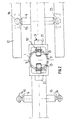
- Fig. 1 eine perspektivische schematische Ansicht einer Stellwand in unterschiedlichen Montagezuständen,
- Fig. 2 einen Horizontalschnitt durch einen vertikalen Pfosten mit einer Draufsicht auf angeschlossene horizotnale Träger.
- Zwischen zwei runden vertikalen Pfosten 1 sind jeweils horizontale Träger 2 angeordnet. Die horizontalen Träger 2 besitzen an ihren Enden jeweils im rechten Winkel angesetzte, fest mit dem horizontalen Träger verbundene U-förmige Schuhe, die jeweils unter einem rechten Winkel zu dem Träger 2 angeordnet sind.
- Die Basis der Schuhe 3 weist jeweils zum Zentrum des zugehörigen Trägers. An den Vorder-und Rückseiten besitzen die Träger Tragzapfen 4.
- Die Schuhe besitzen jeweils einen in Längsrichtung sich erstreckenden Schlitz 5 mit einer Erweiterung 6 in seinem Zentrum.
- Auf Vorder- und Rückseite der Pfosten sind untereinander in Abständen angeordnete, miteinander fluchtende Schlitze 7 angeordnet. Die Schlitze 7 können zur Aufnahme von Tragkonsolen verwendet werden.
- An den einander gegenüberliegenden Seitenflächen sind in den runden Pfosten 1 Gewindemuttern 8 befestigt, in die Befestigungsschrauben 9 eingeschraubt werden können.
- Die Breite der Schlitze 5 ist größer als der Durchmesser des Schaftes 10 der Befestigungsschraube 9. Die Breite ist jedoch geringer als der Durchmesser des Schraubenkopfes 11. Die zentrale Erweiterung 6 besitzt einen größeren Durchmesser als der Schraubenkopf 11.
- Für eine Montage der tragenden Teile werden zunächst die runden Pfosten 1 aufgestellt und dann die Öffnungen 6 über die Köpfe 11 der Befestigungsschrauben geschoben. Die horizontalen Träger fallen so weit nach unten, bis die Schäfte 10 der Schrauben 9 am oberen Ende des Schlitzes 5 anliegen. In dieser Position werden die Befestigungsschrauben 9 angezogen. Durch das Anziehen der Befestigungsschrauben 9 werden die Seitenschenkel der U-förmigen Schuhe fest gegen die Außenseite der runden Pfosten gepreßt. Es entsteht eine absolut steife Verbindung zwischen den horizontalen Trägern und den vertikalen Pfosten.
- Nachdem das aus Pfosten und Trägern bestehende Traggerüst errichtet ist, werden die Kaschierungsteile 12 an die Tragzapfen 4 angehängt. Die Kaschierungsteile 12 besitzen an ihren Rückseiten Aufnahmeelemente 13 mit senkrecht verlaufenden Schlüssellochöffnungen, deren Erweiterungen nach unten weisen. Die Köpfe 14 werden durch die Erweiterungen gesteckt und unter ihrem Eigengewicht fallen die Kaschierungen 12 in die sich anschließenden schmaleren Schlitze ein. Durch die Einschnürung 15 in den Tragzapfen werden die Kaschierungsplatten 12 in einem vorgegebenen Abstand zu den tragenden Elementen gehalten.
Claims (7)
Priority Applications (1)
| Application Number | Priority Date | Filing Date | Title |
|---|---|---|---|
| AT81107755T ATE10126T1 (de) | 1980-10-18 | 1981-09-30 | Stellwand, insbesondere fuer bueros. |
Applications Claiming Priority (2)
| Application Number | Priority Date | Filing Date | Title |
|---|---|---|---|
| DE3039388 | 1980-10-18 | ||
| DE19803039388 DE3039388A1 (de) | 1980-10-18 | 1980-10-18 | Stellwand, insbesondere fuer bueros |
Publications (2)
| Publication Number | Publication Date |
|---|---|
| EP0050241A1 EP0050241A1 (de) | 1982-04-28 |
| EP0050241B1 true EP0050241B1 (de) | 1984-10-31 |
Family
ID=6114672
Family Applications (1)
| Application Number | Title | Priority Date | Filing Date |
|---|---|---|---|
| EP81107755A Expired EP0050241B1 (de) | 1980-10-18 | 1981-09-30 | Stellwand, insbesondere für Büros |
Country Status (4)
| Country | Link |
|---|---|
| EP (1) | EP0050241B1 (de) |
| AT (1) | ATE10126T1 (de) |
| DE (1) | DE3039388A1 (de) |
| ES (1) | ES260808Y (de) |
Cited By (4)
| Publication number | Priority date | Publication date | Assignee | Title |
|---|---|---|---|---|
| US6910306B2 (en) | 1996-12-24 | 2005-06-28 | Steelcase Development Corporation | Knock-down portable partition system |
| DE102008013668A1 (de) * | 2008-03-11 | 2010-05-12 | Claussnitzer, Peter | Bausystem für Displays und Aufsteller |
| US11191178B2 (en) | 2019-01-24 | 2021-11-30 | Steelcase Inc. | Display support system and method for the use thereof |
| US11647834B2 (en) | 2020-07-23 | 2023-05-16 | Steelcase Inc. | Display support system and method for the use thereof |
Families Citing this family (13)
| Publication number | Priority date | Publication date | Assignee | Title |
|---|---|---|---|---|
| GB2129028B (en) * | 1982-10-12 | 1986-01-08 | Robinson Limited Ian J | Collapsible partitioning and/or shelving system |
| DE3617445A1 (de) * | 1986-05-23 | 1988-05-19 | Daimler Benz Ag | Bausatz zur herstellung von trennwaenden o.dgl. |
| CA1295802C (en) * | 1987-05-29 | 1992-02-18 | Mortimer Brown | Panel locking system |
| AT394225B (de) * | 1988-10-05 | 1992-02-25 | Meru Horst Mag | Baukoerper |
| DE9312696U1 (de) * | 1993-08-25 | 1995-01-05 | Kopp, Willi, 71397 Leutenbach | Messebausystem |
| DE9315180U1 (de) * | 1993-10-08 | 1993-12-02 | WSB Wellpappenfabrik GmbH + Co. KG, 68642 Bürstadt | Pfosten mit Verbindungsteilen aus Wellpappe oder Pappe |
| US5806258A (en) * | 1996-06-07 | 1998-09-15 | Haworth, Inc. | Wall panel system |
| US6301846B1 (en) | 1996-12-24 | 2001-10-16 | Steelcase Development Inc. | Knock-down portable partition system |
| US6209273B1 (en) | 1997-05-30 | 2001-04-03 | Steelcase Development Inc. | Panel wall construction |
| US6158178A (en) | 1997-05-30 | 2000-12-12 | Steelcase Inc. | Panel wall construction |
| US6115977A (en) * | 1998-09-11 | 2000-09-12 | Krueger International, Inc. | Knock-down panel partition system |
| US6349516B1 (en) | 1999-06-04 | 2002-02-26 | Haworth, Inc. | Frame arrangement for a wall panel system |
| US20160362854A1 (en) * | 2015-06-12 | 2016-12-15 | Frank Carosella | Particulate containment control for structured support beams |
Family Cites Families (5)
| Publication number | Priority date | Publication date | Assignee | Title |
|---|---|---|---|---|
| US2999570A (en) * | 1957-07-25 | 1961-09-12 | Edward A Seiz | Interlock |
| US3605851A (en) * | 1969-09-22 | 1971-09-20 | Rosemount Partitions Inc | Divider screen assembly |
| DE2327939A1 (de) * | 1973-06-01 | 1974-12-19 | Byggmekanisering Ab | Plattenbauelement zur herstellung einer abschirmung gegen strahlung sowie daraus hergestellte abschirmungen |
| US3987836A (en) * | 1975-02-19 | 1976-10-26 | Standard Desk Limited | Screen partition assembly |
| US4123879A (en) * | 1977-06-27 | 1978-11-07 | American Seating Company | Panel wall systems with modular component build-up |
-
1980
- 1980-10-18 DE DE19803039388 patent/DE3039388A1/de not_active Withdrawn
-
1981
- 1981-09-30 EP EP81107755A patent/EP0050241B1/de not_active Expired
- 1981-09-30 AT AT81107755T patent/ATE10126T1/de not_active IP Right Cessation
- 1981-10-16 ES ES1981260808U patent/ES260808Y/es not_active Expired
Cited By (9)
| Publication number | Priority date | Publication date | Assignee | Title |
|---|---|---|---|---|
| US6910306B2 (en) | 1996-12-24 | 2005-06-28 | Steelcase Development Corporation | Knock-down portable partition system |
| US7448168B2 (en) | 1996-12-24 | 2008-11-11 | Steelcase Inc. | Knock-down portable partition system |
| US7565772B2 (en) | 1996-12-24 | 2009-07-28 | Steelcase, Inc. | Knock-down portable partition system |
| DE102008013668A1 (de) * | 2008-03-11 | 2010-05-12 | Claussnitzer, Peter | Bausystem für Displays und Aufsteller |
| US11191178B2 (en) | 2019-01-24 | 2021-11-30 | Steelcase Inc. | Display support system and method for the use thereof |
| US11903158B2 (en) | 2019-01-24 | 2024-02-13 | Steelcase Inc. | Display support system and method for the use thereof |
| US12444330B2 (en) | 2019-01-24 | 2025-10-14 | Steelcase Inc. | Display support system and method for the use thereof |
| US11647834B2 (en) | 2020-07-23 | 2023-05-16 | Steelcase Inc. | Display support system and method for the use thereof |
| US12690676B2 (en) | 2020-07-23 | 2026-07-28 | Steelcase Inc. | Display support system and method for the use thereof |
Also Published As
| Publication number | Publication date |
|---|---|
| ES260808U (es) | 1982-04-16 |
| EP0050241A1 (de) | 1982-04-28 |
| ATE10126T1 (de) | 1984-11-15 |
| DE3039388A1 (de) | 1982-05-19 |
| ES260808Y (es) | 1982-11-16 |
Similar Documents
| Publication | Publication Date | Title |
|---|---|---|
| DE2553628C3 (de) | Vorrichtung zum Verbinden eines Profilstabes mit an ihm anzubringenden Trägern für die Errichtung von Tragkonstruktionen | |
| EP0050241A1 (de) | Stellwand, insbesondere für Büros | |
| DE2162346C3 (de) | ||
| DE1903129B2 (de) | Vorrichtung zum Anschließen eines Trägers an eine Betonstütze | |
| EP2253764A2 (de) | Rahmenförmiges Fachwerk | |
| DE202023105830U1 (de) | Vorrichtung zur Anbringung von Absturzsicherungen an Baugerüsten | |
| DE2822676A1 (de) | Rohrgeruestsystem, insbesondere fuer baugerueste | |
| DE1912109A1 (de) | Modul-Geruestelemente | |
| EP4692490A1 (de) | Vorrichtung zur anbringung von absturzsicherungen an baugerüsten | |
| WO2022242964A1 (de) | Gerüstträger | |
| DE7320517U (de) | Haltevorrichtung für eine Anhanger kupplung an Kraftfahrzeugen | |
| DE2507577A1 (de) | Einstellbare stuetze fuer mauerwerkschalungen | |
| DE9409626U1 (de) | Balkonkonstruktion | |
| EP0331796B1 (de) | Verstärkte Aufhängevorrichtung für Kabel | |
| EP0814215B1 (de) | Fassadensystem, sowie Befestigungssystem | |
| DE2556365A1 (de) | Stuetzenturm | |
| DE8027911U1 (de) | Stellwand, insbesondere fuer bueros | |
| EP4004305B1 (de) | Montagebaugruppe zur festlegung eines gerüsts an einem bauwerk | |
| DE3148504A1 (de) | Staender fuer ein regalsystem | |
| DE2138483C3 (de) | Traggerüst mit Stielen und Riegeln aus vorgefertigten Stahlbetonelementen | |
| EP4538482A1 (de) | Vorrichtung zur anbringung von absturzsicherungen an baugerüsten | |
| EP0392628B1 (de) | Schalung für zu schüttende Wände, sowie Vertikalträger dafür | |
| DE69609173T2 (de) | Regalsystem | |
| DE1534435C (de) | Zerlegbares Tragwerk fur Brücken od | |
| AT403183B (de) | Schalungstafel |
Legal Events
| Date | Code | Title | Description |
|---|---|---|---|
| PUAI | Public reference made under article 153(3) epc to a published international application that has entered the european phase |
Free format text: ORIGINAL CODE: 0009012 |
|
| AK | Designated contracting states |
Designated state(s): AT BE CH FR GB IT NL |
|
| 17P | Request for examination filed |
Effective date: 19821027 |
|
| ITF | It: translation for a ep patent filed | ||
| GRAA | (expected) grant |
Free format text: ORIGINAL CODE: 0009210 |
|
| AK | Designated contracting states |
Designated state(s): AT BE CH FR GB IT LI NL |
|
| REF | Corresponds to: |
Ref document number: 10126 Country of ref document: AT Date of ref document: 19841115 Kind code of ref document: T |
|
| ET | Fr: translation filed | ||
| PLBE | No opposition filed within time limit |
Free format text: ORIGINAL CODE: 0009261 |
|
| STAA | Information on the status of an ep patent application or granted ep patent |
Free format text: STATUS: NO OPPOSITION FILED WITHIN TIME LIMIT |
|
| 26N | No opposition filed | ||
| ITTA | It: last paid annual fee | ||
| PGFP | Annual fee paid to national office [announced via postgrant information from national office to epo] |
Ref country code: FR Payment date: 19930428 Year of fee payment: 13 |
|
| PGFP | Annual fee paid to national office [announced via postgrant information from national office to epo] |
Ref country code: GB Payment date: 19930914 Year of fee payment: 13 |
|
| PGFP | Annual fee paid to national office [announced via postgrant information from national office to epo] |
Ref country code: CH Payment date: 19930927 Year of fee payment: 13 |
|
| PGFP | Annual fee paid to national office [announced via postgrant information from national office to epo] |
Ref country code: AT Payment date: 19930928 Year of fee payment: 13 |
|
| PGFP | Annual fee paid to national office [announced via postgrant information from national office to epo] |
Ref country code: NL Payment date: 19930930 Year of fee payment: 13 |
|
| PGFP | Annual fee paid to national office [announced via postgrant information from national office to epo] |
Ref country code: BE Payment date: 19931028 Year of fee payment: 13 |
|
| PG25 | Lapsed in a contracting state [announced via postgrant information from national office to epo] |
Ref country code: LI Effective date: 19940930 Ref country code: GB Effective date: 19940930 Ref country code: CH Effective date: 19940930 Ref country code: BE Effective date: 19940930 Ref country code: AT Effective date: 19940930 |
|
| BERE | Be: lapsed |
Owner name: GESIKA BUROMOBELWERK G.M.B.H. & CO. K.G. Effective date: 19940930 |
|
| PG25 | Lapsed in a contracting state [announced via postgrant information from national office to epo] |
Ref country code: NL Effective date: 19950401 |
|
| NLV4 | Nl: lapsed or anulled due to non-payment of the annual fee | ||
| GBPC | Gb: european patent ceased through non-payment of renewal fee |
Effective date: 19940930 |
|
| PG25 | Lapsed in a contracting state [announced via postgrant information from national office to epo] |
Ref country code: FR Effective date: 19950531 |
|
| REG | Reference to a national code |
Ref country code: CH Ref legal event code: PL |
|
| REG | Reference to a national code |
Ref country code: FR Ref legal event code: ST |