EP0048331B1 - Bewegliche Schutzhaube für das angetriebene Werkzeug einer Werkzeugmaschine - Google Patents
Bewegliche Schutzhaube für das angetriebene Werkzeug einer Werkzeugmaschine Download PDFInfo
- Publication number
- EP0048331B1 EP0048331B1 EP81106114A EP81106114A EP0048331B1 EP 0048331 B1 EP0048331 B1 EP 0048331B1 EP 81106114 A EP81106114 A EP 81106114A EP 81106114 A EP81106114 A EP 81106114A EP 0048331 B1 EP0048331 B1 EP 0048331B1
- Authority
- EP
- European Patent Office
- Prior art keywords
- hood
- arm
- shaped piece
- channel
- protective hood
- Prior art date
- Legal status (The legal status is an assumption and is not a legal conclusion. Google has not performed a legal analysis and makes no representation as to the accuracy of the status listed.)
- Expired
Links
Images
Classifications
-
- B—PERFORMING OPERATIONS; TRANSPORTING
- B23—MACHINE TOOLS; METAL-WORKING NOT OTHERWISE PROVIDED FOR
- B23D—PLANING; SLOTTING; SHEARING; BROACHING; SAWING; FILING; SCRAPING; LIKE OPERATIONS FOR WORKING METAL BY REMOVING MATERIAL, NOT OTHERWISE PROVIDED FOR
- B23D59/00—Accessories specially designed for sawing machines or sawing devices
- B23D59/006—Accessories specially designed for sawing machines or sawing devices for removing or collecting chips
- B23D59/0064—Accessories specially designed for sawing machines or sawing devices for removing or collecting chips by suction
-
- B—PERFORMING OPERATIONS; TRANSPORTING
- B23—MACHINE TOOLS; METAL-WORKING NOT OTHERWISE PROVIDED FOR
- B23D—PLANING; SLOTTING; SHEARING; BROACHING; SAWING; FILING; SCRAPING; LIKE OPERATIONS FOR WORKING METAL BY REMOVING MATERIAL, NOT OTHERWISE PROVIDED FOR
- B23D59/00—Accessories specially designed for sawing machines or sawing devices
- B23D59/006—Accessories specially designed for sawing machines or sawing devices for removing or collecting chips
-
- B—PERFORMING OPERATIONS; TRANSPORTING
- B23—MACHINE TOOLS; METAL-WORKING NOT OTHERWISE PROVIDED FOR
- B23Q—DETAILS, COMPONENTS, OR ACCESSORIES FOR MACHINE TOOLS, e.g. ARRANGEMENTS FOR COPYING OR CONTROLLING; MACHINE TOOLS IN GENERAL CHARACTERISED BY THE CONSTRUCTION OF PARTICULAR DETAILS OR COMPONENTS; COMBINATIONS OR ASSOCIATIONS OF METAL-WORKING MACHINES, NOT DIRECTED TO A PARTICULAR RESULT
- B23Q11/00—Accessories fitted to machine tools for keeping tools or parts of the machine in good working condition or for cooling work; Safety devices specially combined with or arranged in, or specially adapted for use in connection with, machine tools
- B23Q11/0042—Devices for removing chips
- B23Q11/0046—Devices for removing chips by sucking
-
- B—PERFORMING OPERATIONS; TRANSPORTING
- B27—WORKING OR PRESERVING WOOD OR SIMILAR MATERIAL; NAILING OR STAPLING MACHINES IN GENERAL
- B27G—ACCESSORY MACHINES OR APPARATUS FOR WORKING WOOD OR SIMILAR MATERIALS; TOOLS FOR WORKING WOOD OR SIMILAR MATERIALS; SAFETY DEVICES FOR WOOD WORKING MACHINES OR TOOLS
- B27G19/00—Safety guards or devices specially adapted for wood saws; Auxiliary devices facilitating proper operation of wood saws
- B27G19/02—Safety guards or devices specially adapted for wood saws; Auxiliary devices facilitating proper operation of wood saws for circular saws
-
- Y—GENERAL TAGGING OF NEW TECHNOLOGICAL DEVELOPMENTS; GENERAL TAGGING OF CROSS-SECTIONAL TECHNOLOGIES SPANNING OVER SEVERAL SECTIONS OF THE IPC; TECHNICAL SUBJECTS COVERED BY FORMER USPC CROSS-REFERENCE ART COLLECTIONS [XRACs] AND DIGESTS
- Y10—TECHNICAL SUBJECTS COVERED BY FORMER USPC
- Y10T—TECHNICAL SUBJECTS COVERED BY FORMER US CLASSIFICATION
- Y10T83/00—Cutting
- Y10T83/202—With product handling means
- Y10T83/2066—By fluid current
- Y10T83/207—By suction means
-
- Y—GENERAL TAGGING OF NEW TECHNOLOGICAL DEVELOPMENTS; GENERAL TAGGING OF CROSS-SECTIONAL TECHNOLOGIES SPANNING OVER SEVERAL SECTIONS OF THE IPC; TECHNICAL SUBJECTS COVERED BY FORMER USPC CROSS-REFERENCE ART COLLECTIONS [XRACs] AND DIGESTS
- Y10—TECHNICAL SUBJECTS COVERED BY FORMER USPC
- Y10T—TECHNICAL SUBJECTS COVERED BY FORMER US CLASSIFICATION
- Y10T83/00—Cutting
- Y10T83/727—With means to guide moving work
- Y10T83/732—With guard
Definitions
- the invention relates to a movable protective hood for the driven tool of a machine tool, in particular for the saw blade of a table saw, with a four-joint parallel link guide for the hood body and a connecting piece for the chip extraction.
- the parallelogram guidance of the hood body allows its position to be adapted to different workpiece thicknesses with a plane-parallel (height) shift of the contact plane of the hood body.
- the arrangement is generally such that, due to spring tension, the weight compensation of the hood body remains above the machine table at any height.
- the connecting piece for the suction hose of a chip extraction is attached directly to the hood body. This not only impedes the observation of the workpiece below the hood body, but also the pushing of the workpiece through the rip fence and its removal from the machine table. Furthermore, the further guidance of the suction hose often collides with other structures of the machine tool.
- the invention is therefore based on the object of improving the chip extraction in a parallelogram-guided protective hood of the type described at the outset so that it does not impair the guidance and handling of the protective hood during operation.
- a link of the four-link parallel link guide is designed as a channel and its one end is connected to the interior of the hood body, while the connecting piece is arranged at its other end.
- the channel link is preferably connected to the hood body by means of a shaped piece which is fixedly connected to the latter, but is pivotably and sealedly mounted on the channel around the one pivot point of the four-bar linkage.
- the channel link and the fitting together form, as it were, a short and a long side of the parallelogram.
- both the channel link and the shaped piece have an essentially flat rectangular cross section, the long rectangular side walls sealing against one another, while sealing pieces attached to the channel link lie sealingly against the shaped piece in the region of the short rectangular side walls.
- the other link is also rotatably mounted on the fitting, which increases the precision of parallel guidance and facilitates assembly.
- the hood body can then - regardless of the handlebar guide - be releasably attached to the fitting.
- the exemplary embodiment represents a protective hood of a table saw.
- the two links of the four-bar parallel link guide namely the channel link 2 and the other link 3, which are described in more detail below, and the other link 3 are pivotally attached to a sign 1 to be fixed in place .
- the channel link 2 consists of a hollow profile of a flat rectangular cross section with long side walls 2a and short side walls 2b. In the area of the short side wall 2b facing the other link 3, the long side walls 2a continue in webs 6, which form a U-profile with the adjacent short side wall 2b (FIG. 2).
- the rectangular profile of the channel link 2 is cut off perpendicular to its hood axis and closed by a pushed-on cap 7, which has a molded connection piece 8 for the spiral hose of the chip extraction.
- the rectangular profile of the channel link 2 is cut off obliquely in the manner shown in FIG. 1, the cut edge following the outer contour of a plastic sealing piece 9 in a partial area of the side walls 2a.
- This outer contour is almost perpendicular to the oblique cutting edge 10.
- the short side wall 2b facing the other link 3 is set back in this end region of the channel link 2 by cutting out; it ends at 11.
- a molded part 12 made of impact-resistant plastic (“Makrolon”) is inserted, which also has an essentially flat rectangular cross section with long side walls 12a and short side walls 12b.
- the “inner” short side wall 12b is, however, angled, as can be seen in FIG. 1, so that there is an almost bumpless transition to the short side wall 2b of the channel link 2 adjacent to the other link 3.
- Two guide webs 13 which are arranged in the interior of the molded body 12 and parallel to its short side walls 12b, which improve the guidance of the suction air and prevent the extracted wood chips from clumping in the region of the deflection.
- a thickening 14 of the one guide web 13 serves to receive the pivot pin 15, the axis of rotation 16 of which forms one of the two pivot points at this end of the handlebar parallelogram.
- a rubber or plastic sealing lip 17 fastened to the adjacent short side wall 2b of the channel link 2 lies against the angled area 12c of the adjacent short side wall 12b of the shaped piece 12 and seals the interior of the channel link 2 in this area from the interior of the shaped piece 12.
- the bend is formed in that the plastic seal 9 is fastened to the side wall 2b (and between the side walls 2a).
- the curvature shown in FIG. 1 corresponds to its radial distance from the axis of rotation 16, and the long side walls 12b of the shaped part 12 have the same curvature in this area.
- Cross braces 18 are provided there for stiffening.
- the "front" axis of rotation 19 of the other link 3 is also provided on the fitting 12; whose short side wall 12b is correspondingly thickened in this area for receiving the pin 20.
- the handlebar 3 is - as shown in FIG. 1 - bent at its ends and partially immersed over most of its length in the U-rail formed by the webs 6 of the channel link 2. This prevents an operator's finger from being accidentally inserted between the handlebars from being squeezed at all height positions of the protective hood when the handlebars 2, 3 approach each other when raised. Furthermore, the space required for the handlebar guide is reduced without reducing the distances between the rotary axes 4 and 5 and 16 and 19 which are important for the guiding accuracy.
- a corresponding thickening 20 of the other short side wall 12b forms a flange-like receptacle for a suitably designed collar 21 at the upper end of the hood body 22.
- This widens in the usual way below and carries - in the cutting direction of the saw blade, not shown - rollers 23 at its outer ends, the connecting tangents 24 indicated by dash-dotted lines in FIG. 1 determining the contact plane of the hood body 22.
Landscapes
- Engineering & Computer Science (AREA)
- Mechanical Engineering (AREA)
- Life Sciences & Earth Sciences (AREA)
- Wood Science & Technology (AREA)
- Forests & Forestry (AREA)
- Sawing (AREA)
- Machine Tool Units (AREA)
- Grinding-Machine Dressing And Accessory Apparatuses (AREA)
- Auxiliary Devices For Machine Tools (AREA)
- Telephone Set Structure (AREA)
Description
- Die Erfindung betrifft eine bewegliche Schutzhaube für das angetriebene Werkzeug einer Werkzeugmaschine, insbesondere für das Sägeblatt einer Tischkreissäge, mit einer Viergelenk-Parallellenker-Führung für den Haubenkörper und einem Anschlussstutzen für die Späne-Absaugung.
- Die Parallelogrammführung des Haubenkörpers erlaubt, dass dessen Stellung unterschiedlichen Werkstückdicken unter planparalleler (Höhen-)Verschiebung der Aufstandsebene des Haubenkörpers angepasst werden kann. Dabei ist die Anordnung im allgemeinen so getroffen, dass infolge Federspannung der Gewichtsausgleich der Haubenkörper in jeder Höhe über dem Maschinentisch stehen bleibt.
- Bei bekannten Anordnungen dieser Art ist der Anschlussstutzen für den Saugschlauch einer Späneabsaugung unmittelbar am Haubenkörper angebracht. Er behindert dadurch nicht nur die Beobachtung des Werkstücks unterhalb des Haubenkörpers, sondern auch das Durchschieben des Werkstücks am Parallelanschlag und seine Abnahme vom Maschinentisch. Ferner kollidiert die weitere Führung des Saugschlauches häufig mit anderen Aufbauten der Werkzeugmaschine.
- Der Erfindung liegt daher die Aufgabe zugrunde, bei einer parallelogrammgeführten Schutzhaube der eingangs beschriebenen Art die Späneabsaugung so zu verbessern, dass sie die Führung und Handhabung der Schutzhaube im Betrieb nicht beeinträchtigen. Zur Lösung dieser Aufgabe ist erfindungsgemäss vorgesehen, dass ein Lenker der Viergelenk-Parallellenker-Führung als Kanal ausgebildet und sein eines Ende an den Innenraum des Haubenkörpers angeschlossen ist, während an seinem anderen Ende der Anschlussstutzen angeordnet ist. Infolge der Integration der Späneabsaugung in die Haubenkörper-Führung wird für die Leitung der Absaugluft im Bereich der Schutzhaube kein zusätzlicher Platz benötigt. Darüberhinaus fällt die unkontrollierbare Beeinflussung der Haubenkörper-Vorspannung durch einen unmittelbar am Haubenkörper angesetzten Absaugschlauch weg. Ein weiterer Vorteil der neuen Anordnung besteht darin, dass das Hohlprofil des Kanallenkers der Parallellenker-Führung eine hohe Stabilität verleiht.
- Vorzugsweise ist der Kanallenker mittels eines Formstücks am Haubenkörper angeschlossen, welches mit diesem fest verbunden, aber am Kanal um den einen Drehpunkt des Viergelenks schwenkbar und abgedichtet gelagert ist. Der Kanallenker und das Formstück zusammen bilden dabei gewissermassen eine kurze und eine lange Seite des Parallelogramms. Dabei ist insbesondere vorgesehen, dass sowohl der Kanallenker als auch das Formstück einen im wesentlichen flachrechteckigen Querschnitt haben, wobei die langen Rechteck-Seitenwände gegeneinander abdichten, während am Kanallenker angesetzte Dichtungsstücke im Bereich der kurzen Rechteck-Seitenwände am Formstück dichtend anliegen. Durch schräges Anschneiden des Kanallenker-Hohlprofils lässt sich dies auf eine Weise bewerkstelligen, die bei unkomplizierter Formgebung des Formstücks nur einfache Abdichtmassnahmen im Bereich der kurzen Rechteck-Seitenwände des Kanallenkers erfordert.
- Gemäss einer bevorzugten Weiterbildung der Erfindung ist am Formstück auch der andere Lenker drehbar gelagert, was die Präzision der Parallelführung erhöht und die Montage erleichtert. Der Haubenkörper kann dann - unabhängig von der Lenkerführung - lösbar am Formstück befestigt sein.
- Weitere vorteilhafte Ausbildungen sind Gegenstände der übrigen Unteransprüche.
- Die nachfolgende Beschreibung veranschaulicht die Erfindung an einem Ausführungsbeispiel anhand derZeichnung. Darin zeigt:
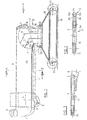
- Fig. 1 einen mittleren Längsschnitt durch die Schutzhaube;
- Fig. 2 einen Schnitt gemäss der Linie 11-11 in Fig. 1 und
- Fig. 3 eine Ansicht von vorn, in Richtung des Pfeiles A in Fig. 1.
- Das Ausführungsbeispiel stellt eine Schutzhaube einer Tischkreissäge dar. An einem ortsfest anzubringenden Schild 1 sind die beiden Lenker der Viergelenk-Parallellenker-Führung, nämlich der - nachfolgend noch näher beschriebene - Kanallenker 2 und der andere Lenker 3 um die Drehpunkte 4 bzw. 5 schwenkbar befestigt. Der Kanallenker 2 besteht aus einem Hohlprofil von flachem Rechteck-Querschnitt mit langen Seitenwänden 2a und kurzen Seitenwänden 2b. Im Bereich der dem anderen Lenker 3 zugewandten kurzen Seitenwand 2b setzen sich die langen Seitenwände 2a in Stegen 6 fort, welche mit der angrenzenden kurzen Seitenwand 2b ein U-Profil bilden (Fig. 2).
- An seinem einen Ende, im Bereich des Schildes 1, ist das Rechteckprofil des Kanallenkers 2 senkrecht zu seiner Haubenachse abgeschnitten und von einer aufgeschobenen Kappe 7 verschlossen, welche einen angeformten Anschlussstutzen 8 für den Spiralschlauch der Späneabsaugung aufweist.
- Am anderen Ende ist das Rechteckprofil des Kanallenkers 2 in der aus Fig. 1 ersichtlichen Weise schräg abgeschnitten, wobei die Schnittkante in einem Teilbereich der Seitenwände 2a der Aussenkontur eines Kunststoff-Dichtungsstücks 9 folgt. Diese Aussenkontur steht nahezu senkrecht auf der schrägen Schnittkante 10. Die dem anderen Lenker 3 zugekehrte kurze Seitenwand 2b ist in diesem Endbereich des Kanallenkers 2 durch Ausschneiden zurückversetzt; sie endet bei 11.
- In diesen Endbereich des Kanallenkers 2 ist ein aus schlagfestem Kunststoff (Wz «Makrolon») hergestelltes Formstück 12 eingesetzt, welches ebenfalls einen im wesentlichen flachrechteckigen Querschnitt mit langen Seitenwänden 12a und kurzen Seitenwänden 12b aufweist. Die «innere» kurze Seitenwand 12b ist jedoch - wie Fig. erkennen lässt - abgewinkelt, so dass ein nahezu stossfreier Übergang zu der dem anderen Lenker 3 benachbarten kurzen Seitenwand 2b des Kanallenkers 2 entsteht. In etwa gleicher Weise abgewinkelt sind zwei im Inneren des Formkörpers 12 parallel zu dessen kurzen Seitenwänden 12b angeordnete Leitstege 13, welche die Führung der Absaugluft verbessern und ein Zusammenballen der abgesaugten Holzspäne im Bereich der Umlenkung verhüten. Eine Verdikkung 14 des einen Leitstegs 13 dient zur Aufnahme des Schwenkzapfens 15, dessen Drehachse 16 den einen der beiden Drehpunkte an diesem Ende des Lenker-Parallelogramms bildet. Eine an der benachbarten kurzen Seitenwand 2b des Kanallenkers 2 befestigte Dichtungslippe 17 aus Gummi oder Kunststoff liegt am abgewinkelten Bereich 12c der benachbarten kurzen Seitenwand 12b des Formstücks 12 an und dichtet den Innenraum des Kanallenkers 2 in diesem Bereich gegenüber dem Innenraum des Formstücks 12 ab. Im Bereich der anderen kurzen Seitenwand 2b des Kanallenkers 2 ist die Abwinklung dadurch gebildet, dass die Kunststoffdichtung 9 an der Seitenwand 2b (und zwischen den Seitenwänden 2a) befestigt ist. Ihre aus Fig. 1 ersichtliche Krümmung entspricht ihrem radialen Abstand von der Drehachse 16, und die gleiche Krümmung weisen in diesem Bereich die langen Seitenwände 12b des Formstücks 12 auf. Zur Aussteifung sind dort Querstege 18 vorgesehen.
- Die «vordere» Drehachse 19 des anderen Lenkers 3 ist ebenfalls am Formstück 12 vorgesehen; dessen kurze Seitenwand 12b ist in diesem Bereich zur Aufnahme des Zapfens 20 entsprechend verdickt. Der Lenker 3 ist - wie Fig. 1 verdeutlicht - an seinen Enden abgekröpft und taucht über den grössten Teil seiner Länge in die von den Stegen 6 des Kanallenkers 2 gebildete U-Schiene teilweise ein. Hierdurch wird in allen Höhenstellungen der Schutzhaube verhindert, dass ein versehentlich zwischen die Lenker gesteckter Finger einer Bedienungsperson gequetscht wird, wenn sich beim Hochstellen die Lenker 2, 3 einander nähern. Weiterhin wird der Raumbedarf der Lenkerführung verringert, ohne die für die Führungsgenauigkeit wichtigen Abstände zwischen den Drehachsen 4 und 5 sowie 16 und 19 zu verringern.
- Mit der für die Aufnahme des Drehzapfens 20 vorgesehenen Verdickung der kurzen Seitenwand 12b des Formstückes 12 bildet eine entsprechende Verdickung 20 der anderen kurzen Seitenwand 12b eine flanschartige Aufnahme für einen entsprechend ausgebildeten Bund 21 am oberen Ende des Haubenkörpers 22. Dieser erweitert sich in üblicher Weise nach unten und trägt - in Schnittrichtung des nicht dargestellten Sägeblatts - an seinen äusseren Enden Rollen 23, deren in Fig. 1 strichpunktiert angegebene Verbindungstangente 24 die Aufstandsebene des Haubenkörpers 22 bestimmt.
Claims (7)
Priority Applications (1)
| Application Number | Priority Date | Filing Date | Title |
|---|---|---|---|
| AT81106114T ATE6224T1 (de) | 1980-09-13 | 1981-08-05 | Bewegliche schutzhaube fuer das angetriebene werkzeug einer werkzeugmaschine. |
Applications Claiming Priority (2)
| Application Number | Priority Date | Filing Date | Title |
|---|---|---|---|
| DE19803034665 DE3034665A1 (de) | 1980-09-13 | 1980-09-13 | Bewegliche schutzhaube fuer das angetriebene werkzeug einer werkzeugmaschine |
| DE3034665 | 1980-09-13 |
Publications (2)
| Publication Number | Publication Date |
|---|---|
| EP0048331A1 EP0048331A1 (de) | 1982-03-31 |
| EP0048331B1 true EP0048331B1 (de) | 1984-02-15 |
Family
ID=6111917
Family Applications (1)
| Application Number | Title | Priority Date | Filing Date |
|---|---|---|---|
| EP81106114A Expired EP0048331B1 (de) | 1980-09-13 | 1981-08-05 | Bewegliche Schutzhaube für das angetriebene Werkzeug einer Werkzeugmaschine |
Country Status (6)
| Country | Link |
|---|---|
| US (1) | US4403534A (de) |
| EP (1) | EP0048331B1 (de) |
| AT (1) | ATE6224T1 (de) |
| DE (1) | DE3034665A1 (de) |
| ES (1) | ES8206803A1 (de) |
| PT (1) | PT73598B (de) |
Families Citing this family (38)
| Publication number | Priority date | Publication date | Assignee | Title |
|---|---|---|---|---|
| DE3340579A1 (de) * | 1983-11-09 | 1985-05-15 | Kölle Maschinenbau GmbH, 7300 Esslingen | Schutzvorrichtung |
| US4825736A (en) * | 1987-09-14 | 1989-05-02 | Westinghouse Electric Corp. | Apparatus for and method of machining around an opening in a workpiece |
| GB2221006A (en) * | 1988-07-19 | 1990-01-24 | Roto Rake Manufacturing Limite | Rotor guard |
| US4896572A (en) * | 1988-11-15 | 1990-01-30 | Norandex Inc. | Saw chip collector |
| DE4014571A1 (de) * | 1990-05-07 | 1991-11-14 | Hilti Ag | Absaugvorrichtung fuer handgefuehrte bohr- und meisselgeraete |
| US5097636A (en) * | 1990-10-26 | 1992-03-24 | Crouch Machinery, Inc. | Edge belt sander with swingable dust hood |
| US5819619A (en) * | 1991-10-09 | 1998-10-13 | Black & Decker Inc. | Dust collection system for compound miter saw |
| US6899005B1 (en) | 1991-10-09 | 2005-05-31 | Black & Decker Inc. | Adjustable fence for compound miter saw |
| US6427570B1 (en) | 1991-10-09 | 2002-08-06 | Black & Decker Inc. | Dust collection system for compound miter saw |
| US5727995A (en) * | 1994-10-24 | 1998-03-17 | Trelawny Pneumatic Tools Division Of Fulton Group Ltd. | Rotary peening tool |
| EP0879681B1 (de) * | 1997-05-22 | 2002-08-07 | Cps S.A. | Sicherheitsvorrichtung für Kreissäge |
| US6470778B1 (en) | 1998-05-20 | 2002-10-29 | Black & Decker Inc. | Dust collector for a power tool |
| US6796208B1 (en) * | 1999-02-19 | 2004-09-28 | Matthew Roy Jorgensen | Sawdust collection hood for table saw |
| CA2285638A1 (en) * | 1999-07-26 | 2001-01-26 | Louis C. Brickner, Jr. | Improved dust collection system |
| DE20103373U1 (de) * | 2001-02-27 | 2001-08-09 | Wilhelm Altendorf GmbH & Co KG, 32429 Minden | Schutzvorrichtung für eine Stand-Kreissäge |
| DE10340097B3 (de) * | 2003-08-30 | 2004-11-11 | Siempelkamp Maschinen- Und Anlagenbau Gmbh & Co. Kg | Vorrichtung zum Besäumen der Seitenränder von Matten aus Holzwerkstoffen |
| US7434604B2 (en) | 2004-07-30 | 2008-10-14 | Black & Decker Inc. | Jig apparatus |
| US7857020B2 (en) | 2004-07-30 | 2010-12-28 | Black & Decker Inc. | Jig apparatus |
| US7455089B2 (en) | 2004-07-30 | 2008-11-25 | Black & Decker Inc. | Jig apparatus |
| USD571836S1 (en) | 2006-08-22 | 2008-06-24 | Black & Decker Inc. | Box joint template |
| USD575312S1 (en) | 2006-08-22 | 2008-08-19 | Black & Decker Inc. | Outrigger for a jig apparatus |
| USD577752S1 (en) | 2006-08-22 | 2008-09-30 | Black & Decker Inc. | Jig apparatus |
| USD559287S1 (en) | 2006-08-22 | 2008-01-08 | Black & Decker Corporation | Variable-spaced finger assembly |
| USD559875S1 (en) | 2006-08-22 | 2008-01-15 | Black & Decker Corporation | Half-blind router bit depth guide |
| USD573615S1 (en) | 2006-08-22 | 2008-07-22 | Black & Decker Inc. | Dust collector |
| USD569882S1 (en) | 2006-08-22 | 2008-05-27 | Black & Decker Inc. | Miniature variable-spaced finger assembly |
| USD560235S1 (en) | 2006-08-22 | 2008-01-22 | Black & Decker Corporation | Sliding tapered dovetail and fixed half-blind dovetail template |
| USD574864S1 (en) | 2006-08-22 | 2008-08-12 | Black & Decker Inc | Mortise and tenon assembly |
| TWM317912U (en) * | 2006-11-13 | 2007-09-01 | Jia Hsin Cheng Entpr Co Ltd | Circular saw with dust-collecting cover |
| US20100037740A1 (en) * | 2008-08-18 | 2010-02-18 | Kun-Yen Lin | Dust Control Hood Assembly for a Cutting Machine |
| US8082825B2 (en) | 2009-06-09 | 2011-12-27 | Butler David J | Health and safety system for a table saw |
| US8371198B2 (en) * | 2009-08-20 | 2013-02-12 | Joseph Babine | Table saw fence engagement and blade guard apparatus |
| US9221110B2 (en) * | 2009-10-02 | 2015-12-29 | JPL Global, LLC | Power saw apparatus with integrated dust collector |
| US9956626B2 (en) * | 2016-03-05 | 2018-05-01 | Siruceo Dustless LLC | Dustless table saw |
| CN108284486B (zh) * | 2018-02-08 | 2023-04-07 | 永康市丛臻工具有限公司 | 一种无尘台锯台面除尘防护罩 |
| EP3865238A1 (de) * | 2020-02-11 | 2021-08-18 | Hilti Aktiengesellschaft | Vorrichtung und system zum abdecken eines mit einem werkzeuggerät erzeugbaren schnittspalts, sowie verfahren zum absaugen von staub aus einem arbeitsbereich eines werkzeuggeräts |
| CN111451579A (zh) * | 2020-04-26 | 2020-07-28 | 上海聚阔自动化设备有限公司 | 汽车踏板生产用修边装置 |
| CN111531229A (zh) * | 2020-05-15 | 2020-08-14 | 常山正丽机电有限公司 | 一种电机壳体冷挤压成型装置 |
Family Cites Families (8)
| Publication number | Priority date | Publication date | Assignee | Title |
|---|---|---|---|---|
| US1712828A (en) * | 1927-02-14 | 1929-05-14 | Henry J Klehm | Saw guard |
| US2593596A (en) * | 1949-03-24 | 1952-04-22 | George V Olson | Circular saw guard |
| CH426209A (de) * | 1965-10-06 | 1966-12-15 | Stahl Leo | Schutzvorrichtung an Kreissäge oder -fräse für Holzbearbeitung |
| US3832922A (en) * | 1973-03-19 | 1974-09-03 | Commander Ind Inc | Automatic back rip machine |
| US3945281A (en) * | 1974-08-05 | 1976-03-23 | Kreitz Lloyd D | Dust collector for radial arm saws |
| US4063478A (en) * | 1976-10-20 | 1977-12-20 | Diebold Incorporated | Saw enclosure construction |
| US4253362A (en) * | 1979-08-13 | 1981-03-03 | Olson Larry E | Apparatus for collecting sawdust produced by a circular power saw |
| US4255995A (en) * | 1980-01-24 | 1981-03-17 | Connor J Franklin | Dust confining and collection housing for power table saws and the like |
-
1980
- 1980-09-13 DE DE19803034665 patent/DE3034665A1/de active Granted
-
1981
- 1981-08-05 AT AT81106114T patent/ATE6224T1/de not_active IP Right Cessation
- 1981-08-05 EP EP81106114A patent/EP0048331B1/de not_active Expired
- 1981-08-19 ES ES504822A patent/ES8206803A1/es not_active Expired
- 1981-08-31 PT PT73598A patent/PT73598B/de not_active IP Right Cessation
- 1981-09-11 US US06/301,204 patent/US4403534A/en not_active Expired - Lifetime
Also Published As
| Publication number | Publication date |
|---|---|
| DE3034665C2 (de) | 1987-12-03 |
| DE3034665A1 (de) | 1982-09-30 |
| ES504822A0 (es) | 1982-08-16 |
| US4403534A (en) | 1983-09-13 |
| ES8206803A1 (es) | 1982-08-16 |
| PT73598A (de) | 1981-09-01 |
| PT73598B (de) | 1983-09-27 |
| ATE6224T1 (de) | 1984-03-15 |
| EP0048331A1 (de) | 1982-03-31 |
Similar Documents
| Publication | Publication Date | Title |
|---|---|---|
| EP0048331B1 (de) | Bewegliche Schutzhaube für das angetriebene Werkzeug einer Werkzeugmaschine | |
| EP2127969B1 (de) | Wischblatt | |
| DE19609120C2 (de) | Schneidspan-Absaugeinrichtung zur Verwendung bei einem Schneidwerkzeug | |
| DE60301306T2 (de) | Staubabsaugung für eine Gehrungssäge | |
| DE3243564C2 (de) | Führungsplatte zum kontrollierten Leiten einer transportablen Säge | |
| EP1925388B1 (de) | Tischkreissäge | |
| DE202004000983U1 (de) | Kappsäge mit Staubfangvorrichtung | |
| DE60215719T2 (de) | Staubsammler für ein Kraftwerkzeug | |
| DE2433744A1 (de) | Reinigungsvorrichtung mit einem kombinierten saug- und blasmundstueck | |
| DE102016000718A1 (de) | Handgeführtes Arbeitsgerät mit einer Führungsschiene | |
| EP0311858B1 (de) | Schutzverkleidung für eine Werkzeugmaschine mit einer Beschickungstür | |
| DE3615736C2 (de) | ||
| DE102007049708A1 (de) | Gebaute Fußplatte für handgeführte Werkzeugmaschinen | |
| DE3843912A1 (de) | Elektrohandwerkzeug mit spaenekanal und absaugstutzen | |
| EP1902822B1 (de) | Sicherheitseinrichtung für Kreissägeblatt oder dgl. | |
| EP0212308A1 (de) | Arthroskopie-Instrument mit Absaugrohr | |
| DE1185346B (de) | Staubsaugerwerkzeug mit zwei Mundstueckkoerpern | |
| EP3944940B1 (de) | Sägemaschine | |
| EP0025547A1 (de) | Vorrichtung zum Einfalten der Bodenklappen einer Faltschachtel | |
| DE610082C (de) | Mit Handgriff versehene, vorzugsweise zur Blechbearbeitung bestimmte elektrisch angetriebene Stichsaege | |
| DE7820060U1 (de) | Kapp- und gehrungskreissaege | |
| DE3730273A1 (de) | Vorrichtung zum absaugen von rauch und schadstoffen | |
| DE29508107U1 (de) | Schutzhaube | |
| EP0329982A2 (de) | Werkzeugmaschine | |
| DE2754186A1 (de) | Handkreissaege mit einer in der schutzhaube der saege angebrachten spanauswurfoeffnung |
Legal Events
| Date | Code | Title | Description |
|---|---|---|---|
| PUAI | Public reference made under article 153(3) epc to a published international application that has entered the european phase |
Free format text: ORIGINAL CODE: 0009012 |
|
| AK | Designated contracting states |
Designated state(s): AT BE CH FR GB IT NL SE |
|
| 17P | Request for examination filed |
Effective date: 19820121 |
|
| ITF | It: translation for a ep patent filed | ||
| GRAA | (expected) grant |
Free format text: ORIGINAL CODE: 0009210 |
|
| AK | Designated contracting states |
Designated state(s): AT BE CH FR GB IT LI NL SE |
|
| REF | Corresponds to: |
Ref document number: 6224 Country of ref document: AT Date of ref document: 19840315 Kind code of ref document: T |
|
| ET | Fr: translation filed | ||
| PLBE | No opposition filed within time limit |
Free format text: ORIGINAL CODE: 0009261 |
|
| STAA | Information on the status of an ep patent application or granted ep patent |
Free format text: STATUS: NO OPPOSITION FILED WITHIN TIME LIMIT |
|
| 26N | No opposition filed | ||
| ITTA | It: last paid annual fee | ||
| PGFP | Annual fee paid to national office [announced via postgrant information from national office to epo] |
Ref country code: GB Payment date: 19940801 Year of fee payment: 14 |
|
| PGFP | Annual fee paid to national office [announced via postgrant information from national office to epo] |
Ref country code: AT Payment date: 19940823 Year of fee payment: 14 |
|
| PGFP | Annual fee paid to national office [announced via postgrant information from national office to epo] |
Ref country code: SE Payment date: 19940824 Year of fee payment: 14 |
|
| PGFP | Annual fee paid to national office [announced via postgrant information from national office to epo] |
Ref country code: NL Payment date: 19940831 Year of fee payment: 14 |
|
| PGFP | Annual fee paid to national office [announced via postgrant information from national office to epo] |
Ref country code: BE Payment date: 19940902 Year of fee payment: 14 |
|
| PGFP | Annual fee paid to national office [announced via postgrant information from national office to epo] |
Ref country code: CH Payment date: 19940921 Year of fee payment: 14 |
|
| EAL | Se: european patent in force in sweden |
Ref document number: 81106114.2 |
|
| PG25 | Lapsed in a contracting state [announced via postgrant information from national office to epo] |
Ref country code: GB Effective date: 19950805 Ref country code: AT Effective date: 19950805 |
|
| PG25 | Lapsed in a contracting state [announced via postgrant information from national office to epo] |
Ref country code: SE Effective date: 19950806 |
|
| PG25 | Lapsed in a contracting state [announced via postgrant information from national office to epo] |
Ref country code: LI Effective date: 19950831 Ref country code: CH Effective date: 19950831 Ref country code: BE Effective date: 19950831 |
|
| BERE | Be: lapsed |
Owner name: WILHELM ALTENDORF G.M.B.H. & CO. K.G. Effective date: 19950831 |
|
| PG25 | Lapsed in a contracting state [announced via postgrant information from national office to epo] |
Ref country code: NL Effective date: 19960301 |
|
| GBPC | Gb: european patent ceased through non-payment of renewal fee |
Effective date: 19950805 |
|
| REG | Reference to a national code |
Ref country code: CH Ref legal event code: PL |
|
| NLV4 | Nl: lapsed or anulled due to non-payment of the annual fee |
Effective date: 19960301 |
|
| EUG | Se: european patent has lapsed |
Ref document number: 81106114.2 |
|
| PGFP | Annual fee paid to national office [announced via postgrant information from national office to epo] |
Ref country code: FR Payment date: 19970717 Year of fee payment: 17 |
|
| PG25 | Lapsed in a contracting state [announced via postgrant information from national office to epo] |
Ref country code: FR Free format text: LAPSE BECAUSE OF NON-PAYMENT OF DUE FEES Effective date: 19990430 |
|
| REG | Reference to a national code |
Ref country code: FR Ref legal event code: ST |