EP0046510A2 - Stützlager für eine Bremswelle - Google Patents
Stützlager für eine Bremswelle Download PDFInfo
- Publication number
- EP0046510A2 EP0046510A2 EP81105778A EP81105778A EP0046510A2 EP 0046510 A2 EP0046510 A2 EP 0046510A2 EP 81105778 A EP81105778 A EP 81105778A EP 81105778 A EP81105778 A EP 81105778A EP 0046510 A2 EP0046510 A2 EP 0046510A2
- Authority
- EP
- European Patent Office
- Prior art keywords
- brake
- brake shaft
- sheet metal
- metal shells
- rubber bushing
- Prior art date
- Legal status (The legal status is an assumption and is not a legal conclusion. Google has not performed a legal analysis and makes no representation as to the accuracy of the status listed.)
- Granted
Links
Images
Classifications
-
- F—MECHANICAL ENGINEERING; LIGHTING; HEATING; WEAPONS; BLASTING
- F16—ENGINEERING ELEMENTS AND UNITS; GENERAL MEASURES FOR PRODUCING AND MAINTAINING EFFECTIVE FUNCTIONING OF MACHINES OR INSTALLATIONS; THERMAL INSULATION IN GENERAL
- F16D—COUPLINGS FOR TRANSMITTING ROTATION; CLUTCHES; BRAKES
- F16D65/00—Parts or details
- F16D65/14—Actuating mechanisms for brakes; Means for initiating operation at a predetermined position
- F16D65/16—Actuating mechanisms for brakes; Means for initiating operation at a predetermined position arranged in or on the brake
- F16D65/22—Actuating mechanisms for brakes; Means for initiating operation at a predetermined position arranged in or on the brake adapted for pressing members apart, e.g. for drum brakes
-
- F—MECHANICAL ENGINEERING; LIGHTING; HEATING; WEAPONS; BLASTING
- F16—ENGINEERING ELEMENTS AND UNITS; GENERAL MEASURES FOR PRODUCING AND MAINTAINING EFFECTIVE FUNCTIONING OF MACHINES OR INSTALLATIONS; THERMAL INSULATION IN GENERAL
- F16C—SHAFTS; FLEXIBLE SHAFTS; ELEMENTS OR CRANKSHAFT MECHANISMS; ROTARY BODIES OTHER THAN GEARING ELEMENTS; BEARINGS
- F16C27/00—Elastic or yielding bearings or bearing supports, for exclusively rotary movement
- F16C27/06—Elastic or yielding bearings or bearing supports, for exclusively rotary movement by means of parts of rubber or like materials
- F16C27/063—Sliding contact bearings
-
- F—MECHANICAL ENGINEERING; LIGHTING; HEATING; WEAPONS; BLASTING
- F16—ENGINEERING ELEMENTS AND UNITS; GENERAL MEASURES FOR PRODUCING AND MAINTAINING EFFECTIVE FUNCTIONING OF MACHINES OR INSTALLATIONS; THERMAL INSULATION IN GENERAL
- F16C—SHAFTS; FLEXIBLE SHAFTS; ELEMENTS OR CRANKSHAFT MECHANISMS; ROTARY BODIES OTHER THAN GEARING ELEMENTS; BEARINGS
- F16C2361/00—Apparatus or articles in engineering in general
- F16C2361/45—Brakes
-
- F—MECHANICAL ENGINEERING; LIGHTING; HEATING; WEAPONS; BLASTING
- F16—ENGINEERING ELEMENTS AND UNITS; GENERAL MEASURES FOR PRODUCING AND MAINTAINING EFFECTIVE FUNCTIONING OF MACHINES OR INSTALLATIONS; THERMAL INSULATION IN GENERAL
- F16D—COUPLINGS FOR TRANSMITTING ROTATION; CLUTCHES; BRAKES
- F16D2125/00—Components of actuators
- F16D2125/18—Mechanical mechanisms
- F16D2125/20—Mechanical mechanisms converting rotation to linear movement or vice versa
- F16D2125/22—Mechanical mechanisms converting rotation to linear movement or vice versa acting transversely to the axis of rotation
- F16D2125/28—Cams; Levers with cams
- F16D2125/30—Cams; Levers with cams acting on two or more cam followers, e.g. S-cams
-
- F—MECHANICAL ENGINEERING; LIGHTING; HEATING; WEAPONS; BLASTING
- F16—ENGINEERING ELEMENTS AND UNITS; GENERAL MEASURES FOR PRODUCING AND MAINTAINING EFFECTIVE FUNCTIONING OF MACHINES OR INSTALLATIONS; THERMAL INSULATION IN GENERAL
- F16D—COUPLINGS FOR TRANSMITTING ROTATION; CLUTCHES; BRAKES
- F16D2125/00—Components of actuators
- F16D2125/18—Mechanical mechanisms
- F16D2125/44—Mechanical mechanisms transmitting rotation
- F16D2125/56—Shafts for transmitting torque directly
Definitions
- the invention relates to a support bearing for a brake shaft of an inner shoe brake with a support plate attached to the axle body and two sheet metal shells connected to it.
- Support bearings of the type described above for a brake shaft of an inner-back brake consist of a support plate attached to the axle body, to which a plain bearing surrounding the brake shaft is attached.
- the plain bearing is formed by a sliding body made of sintered steel, which is surrounded by the two sheet metal shells and is centered with them on the support plate.
- This known plain bearing has the disadvantage that it has to be relubricated from time to time.
- the object of the invention is to create a simply constructed, maintenance-free support bearing for a brake shaft of an inner shoe brake, which can also be easily assembled and disassembled.
- the two sheet metal shells can be provided with anchoring holes in their jacket for the rubber bushing.
- a support bearing designed according to the invention has on the one hand the advantage of a very simple and inexpensive construction and on the other hand the further advantage that it is completely maintenance-free.
- the volume of the rubber bushing must be chosen so large that a non-slip preload on the brake shaft is possible with the sheet metal shells.
- the angle of rotation is then compensated for by the rubber bushing without slipping on the brake shaft.
- the anchoring holes in the jacket of the two metal shells prevent the rubber bush from slipping in relation to the metal shells.
- the slip-free mounting of the brake shaft in the support bearing with the rubber bushing arranged and designed according to the invention results restoring forces in the support bearing when the brake is actuated.
- there is an advantage of the invention in that, due to the non-slip bearing, special machining of the brake shaft in the region of the support bearing is no longer necessary.
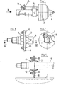
- a wheel hub 2 with an attached brake drum 3 is rotatably mounted on an axle body 1.
- the brake drum 3 is a - not shown - inside arranged shoe brake, which is actuated via a brake shaft 4.
- the support bearing 5 consists of a support plate 6 fastened to the axle body 1, two sheet metal shells 7, 8, a rubber bushing 9 and a plurality of fastening screws 10. Both sheet metal shells 7, 8 are clamped together on the same side of the support plate 6 with the fastening screws 10, namely on the to a brake lever 11 pointing side. In this way, the support bearing 5 can be pushed onto or removed from the brake shaft 4 when the brake lever 11 is not attached.
- the rubber bushing 9 is pressed together with the two sheet metal shells 7, 8 and pressed onto the brake shaft 4 with pretension.
- the rubber bushing is pressed in a wart-like manner into anchoring holes 12 in the two sheet metal shells 7 and 8. This also prevents the rubber bushing 9 from slipping in relation to the two sheet metal shells 7, 8.
Landscapes
- Engineering & Computer Science (AREA)
- General Engineering & Computer Science (AREA)
- Mechanical Engineering (AREA)
- Braking Arrangements (AREA)
Abstract
Description
- Die Erfindung betrifft ein Stützlager für eine Bremswelle einer Innenbackenbremse mit einer am Achskörper befestigten Stützplatte und zwei mit dieser verbundenen Blechschalen.
- Stützlager der vorstehend beschriebenen Gattung für eine Bremswelle einer Innenbckenbremse sind bekannt. Sie bestehen aus einer am Achskörper befestigten Stützplatte, an der ein die Bremswelle umgebendes Gleitlager befestigt ist. Das Gleitlager wird von einem Gleitkörper aus Sinterstahl gebildet, der von den beiden Blechschalen umgeben ist und mit diesen an der Stützplatte zentriert wird. Dieses bekannte Gleitlager hat den Nachteil, daß es von Zeit zu Zeit nachgeschmiert werden muß.
- Davon ausgehend liegt der Erfindung die Aufgabe zugrunde, ein einfach konstruiertes, wartungsfreies Stützlager für eine Bremswelle einer Innenbackenbremse zu schaffen, welches auch einfach montiert und demontiert werden kann.
- Zur Lösung dieser Aufgabe wird vorgeschlagen, zwischen den beiden bekannten Blechschalen eine Gummibuchse auf der Bremswelle anzuordnen und mit den Blechschalen vorzuspannen.
- In weiterer Ausgestaltung der Erfindung können die beiden Blechschalen in ihrem Mantel mit Verankerungs.L löchern für die Gummibuchse versehen sein. Außerdem hat es sich als zweckmäßig erwiesen, die beiden Blechschalen auf der gleichen Seite an der Stützplatte zu befestigen, und zwar auf der zum Bremshebel hin zeigenden Seite. Bei dieser Anordnung ist es möglich, das Stützlager nach einer Demontage des Bremshebels und dem Lösen der Befestigungsschrauben von der Bremswelle abzuziehen, ohne die Bremswelle selbst demontieren zu müssen.
- Ein erfindungsgemäß ausgebildetes Stützlager hat einerseits den Vorteil eines sehr einfachen und preiswerten Aufbaues und andererseits den weiteren Vorteil, daß es vollständig wartungsfrei ist. Dafür muß das Volumen der Gummibuchse so groß gewählt werden, daß mit den Blechschalen eine rutschfeste Vorspannung auf der Bremswelle möglich ist. Der Verdrehwinkel wird dann von der Gummibuchse ohne Schlupf auf der Bremswelle ausgeglichen. Die Verankerungslöcher im Mantel der beiden Blechschalen verhindern einen Schlupf der Gummibuchse im Verhältnis zu den Blechschalen. Durch die schlupffreie Lagerung der Bremswelle im Stützlager mit der erfindungsgemäß angeordneten und ausgebildeten Gummibuchse entstehen beim Betätigen der Bremse Rückstellkräfte im Stützlager. Schließlich besteht noch ein Vorteil der Erfindung darin, daß infolge der schlupffreien Lagerung eine Sonderbearbeitung der Bremswelle im Bereich des Stützlagers nicht mehr erforderlich ist.
- Weitere Einzelheiten und Vorteile des Gegenstandes der Erfindung ergeben sich aus der nachfolgenden Beschreibung der zugehörigen Zeichnung, in der eine bevorzugte Ausführungsform eines erfindungsgemäß ausgebildeten Stützlagers schematisch dargestellt worden ist. In der Zeichnung zeigen :
- Fig. 1 eine Hälfte einer Achse mit einer Innenbackenbremse und einer Bremswelle in Draufsicht;
- Fig. 2 dieselbe Achse in Richtung des Pfeiles II in Seitenansicht;
- Fig. 3 eine vergrößerte Darstellung des Stützlagers in Draufsicht;
- Fig. 4 die vergrößerte Darstellung des Stützlagers entlang der Linie IV-IV in Fig. 3 geschnitten.
- An einem Achskörper 1 ist eine Radnabe 2 mit einer daran befestigten Bremstrommel 3 drehbar gelagert. In der Bremstrommel 3 ist eine - nicht dargestellte - Innenbackenbremse angeordnet, die über eine Bremswelle 4 betätigt wird.
- Außerhalb der Bremstrommel 3 ist die Bremswelle 4 mit einem Stützlager 5 am Achskörper 1 gelagert. Das Stützlager 5 besteht aus einer am Achskörper 1 befstigten Stützplatte 6, zwei Blechschalen 7, 8, einer Gummibuchse 9 und mehreren Befestigungsschrauben 10. Beide Blechschalen 7, 8 sind auf der gleichen Seite der Stützplatte 6 mit den Befestigungsschrauben 10 zusammengespannt, und zwar auf der zu einem Bremshebel 11 hin zeigenden Seite. Auf diese Weise kann das Stützlager 5 auf die Bremswelle 4 aufgeschoben oder von dieser wieder abgezogen werden, wenn der Bremshebel 11 nicht aufgesteckt ist.
- Die Gummibuchse 9 wird mit den beiden Blechschalen 7, 8 zusammengedrückt und mit Vorspannung auf die Bremswelle 4 gepreßt. Dabei drückt sich die Gummibuchse warzenförmig in Verankerungslöcher 12 der beiden Blechschalen 7 und 8. Auf diese Weise wird auch ein Schlüpfen der Gummibuchse 9 im Verhältnis zu den beiden Blechschalen 7, 8 verhindert.
- Alle in der Beschreibung erwähnten und in der Zeichnung dargestellten neuen Merkmale sind erfindungswesentlich, auch soweit sie in den Ansprüchen nicht ausdrücklich gekennzeichnet worden sind.
-
- 1 Achskörper
- 2 Radnabe
- 3 Bremstrommel
- 4 Bremswelle
- 5 Stützlager
- 6 Stützplatte
- 7 Blechschale
- 8 Blechschale
- 9 Gummibuchse
- 10 Befestigungsschraube
- 11 Bremshebel
- 12 Verankerungsloch
Claims (3)
Applications Claiming Priority (2)
| Application Number | Priority Date | Filing Date | Title |
|---|---|---|---|
| DE8022262 | 1980-08-21 | ||
| DE8022262U | 1980-08-21 |
Publications (3)
| Publication Number | Publication Date |
|---|---|
| EP0046510A2 true EP0046510A2 (de) | 1982-03-03 |
| EP0046510A3 EP0046510A3 (en) | 1982-03-17 |
| EP0046510B1 EP0046510B1 (de) | 1983-12-28 |
Family
ID=6718178
Family Applications (1)
| Application Number | Title | Priority Date | Filing Date |
|---|---|---|---|
| EP81105778A Expired EP0046510B1 (de) | 1980-08-21 | 1981-07-22 | Stützlager für eine Bremswelle |
Country Status (2)
| Country | Link |
|---|---|
| EP (1) | EP0046510B1 (de) |
| DE (1) | DE3161784D1 (de) |
Cited By (1)
| Publication number | Priority date | Publication date | Assignee | Title |
|---|---|---|---|---|
| CN101619749B (zh) * | 2008-07-03 | 2012-02-15 | 塞夫霍兰德有限公司 | 轴承装置 |
Family Cites Families (7)
| Publication number | Priority date | Publication date | Assignee | Title |
|---|---|---|---|---|
| DE8022262U1 (de) * | 1980-11-20 | Bergische Achsenfabrik Fr. Kotz & Soehne, 5276 Wiehl | Stützlager für eine Bremswelle | |
| US1940302A (en) * | 1930-02-17 | 1933-12-19 | Chrysler Corp | Oscillating joint |
| US2739851A (en) * | 1952-12-24 | 1956-03-27 | Thompson Prod Inc | Shaft bearing mounting |
| US2923579A (en) * | 1954-07-06 | 1960-02-02 | Rockwell Standard Co | Shaft support |
| BE643087A (de) * | 1963-01-28 | |||
| DE1680219C3 (de) * | 1966-06-20 | 1979-01-25 | Rockwell International Corp., Pittsburgh, Pa. (V.St.A.) | Einstellbares Lager für eine Bremsnockenwelle |
| DE2330864A1 (de) * | 1973-06-16 | 1975-01-09 | Georg Maerz | Geraeuscharmes, schall- und stossdaempfendes gleitlager |
-
1981
- 1981-07-22 DE DE8181105778T patent/DE3161784D1/de not_active Expired
- 1981-07-22 EP EP81105778A patent/EP0046510B1/de not_active Expired
Cited By (1)
| Publication number | Priority date | Publication date | Assignee | Title |
|---|---|---|---|---|
| CN101619749B (zh) * | 2008-07-03 | 2012-02-15 | 塞夫霍兰德有限公司 | 轴承装置 |
Also Published As
| Publication number | Publication date |
|---|---|
| EP0046510B1 (de) | 1983-12-28 |
| DE3161784D1 (en) | 1984-02-02 |
| EP0046510A3 (en) | 1982-03-17 |
Similar Documents
| Publication | Publication Date | Title |
|---|---|---|
| DE3200610A1 (de) | Riemenspannvorrichtung fuer einen von einem motor angetriebenen treibriemen fuer hilfsaggregate von kraftfahrzeugen | |
| DE69602514T2 (de) | Verbesserungen in und bezüglich auf Fahrrad-Antriebsanordnungen | |
| DE602004010997T2 (de) | Bremse für ein Flugzeugrad, gebremstes Flugzeugrad, sowie Landegestell mit einem solchen Flugzeugrad | |
| DE2652292B2 (de) | Am Werkstück befestigbares Gerät zum Schleifen von ebenen, ringförmigen Dichtflächen | |
| DE2405592A1 (de) | Laufrolle, insbesondere fuer einen stuhl oder dergleichen | |
| EP0046510A2 (de) | Stützlager für eine Bremswelle | |
| DE3503817C1 (de) | Vorrichtung zum Zerkleinern und/oder Mischen von festen,pastoesen und/oder fluessigen Stoffen | |
| DE8533440U1 (de) | Körpertrainingsgerät | |
| DE8022262U1 (de) | Stützlager für eine Bremswelle | |
| DE2260108C3 (de) | Lenkrolle für verfahrbare Krankenhausbetten o.dgl. Gegenstände | |
| DE2502194C3 (de) | Schlüsselschalter | |
| DE3146165C2 (de) | ||
| DE1965263B2 (de) | Dichtungseinrichtung an einer kontinuierlich arbeitenden entwaesserungspresse | |
| DE1199965B (de) | Zum Abschaelen der Borke von Baumstaemmen dienende Trommel | |
| DE19500002C2 (de) | Rollenwagen für die Verlegung von transportablen Brücken | |
| DE843046C (de) | Befestigung von getriebenen oder treibenden Scheiben auf Wellen | |
| DE1169393B (de) | Getriebe fuer den Antrieb eines Kohlenhobels | |
| EP0210515B1 (de) | Verteilmaschine, insbesondere Sämaschine | |
| DE3920172C2 (de) | ||
| AT328234B (de) | Seilrolle | |
| AT219098B (de) | Übersetzungsreibantrieb | |
| DE691168C (de) | Schraem- und Schlitzmaschine mit einem Schraemkopfschwenkgetriebe | |
| DE4227192C1 (de) | Reibradgetriebe für winkelgenaue Übertragung | |
| DE1575914C3 (de) | Bremsvorrichtung, insbesondere zum Abbremsen von über eine Rollenfördereinrichtung bewegten Lasten | |
| AT253039B (de) | Elektromechanischer Zeitgeber |
Legal Events
| Date | Code | Title | Description |
|---|---|---|---|
| PUAI | Public reference made under article 153(3) epc to a published international application that has entered the european phase |
Free format text: ORIGINAL CODE: 0009012 |
|
| PUAL | Search report despatched |
Free format text: ORIGINAL CODE: 0009013 |
|
| AK | Designated contracting states |
Designated state(s): DE FR GB IT SE |
|
| AK | Designated contracting states |
Designated state(s): DE FR GB IT SE |
|
| 17P | Request for examination filed |
Effective date: 19820304 |
|
| ITF | It: translation for a ep patent filed | ||
| GRAA | (expected) grant |
Free format text: ORIGINAL CODE: 0009210 |
|
| AK | Designated contracting states |
Designated state(s): DE FR GB IT SE |
|
| REF | Corresponds to: |
Ref document number: 3161784 Country of ref document: DE Date of ref document: 19840202 |
|
| ET | Fr: translation filed | ||
| PGFP | Annual fee paid to national office [announced via postgrant information from national office to epo] |
Ref country code: FR Payment date: 19840810 Year of fee payment: 4 |
|
| PGFP | Annual fee paid to national office [announced via postgrant information from national office to epo] |
Ref country code: DE Payment date: 19840919 Year of fee payment: 4 |
|
| PGFP | Annual fee paid to national office [announced via postgrant information from national office to epo] |
Ref country code: SE Payment date: 19840930 Year of fee payment: 4 |
|
| PLBE | No opposition filed within time limit |
Free format text: ORIGINAL CODE: 0009261 |
|
| STAA | Information on the status of an ep patent application or granted ep patent |
Free format text: STATUS: NO OPPOSITION FILED WITHIN TIME LIMIT |
|
| 26N | No opposition filed | ||
| PG25 | Lapsed in a contracting state [announced via postgrant information from national office to epo] |
Ref country code: GB Effective date: 19890722 |
|
| PG25 | Lapsed in a contracting state [announced via postgrant information from national office to epo] |
Ref country code: SE Effective date: 19890723 |
|
| GBPC | Gb: european patent ceased through non-payment of renewal fee | ||
| PG25 | Lapsed in a contracting state [announced via postgrant information from national office to epo] |
Ref country code: FR Free format text: LAPSE BECAUSE OF NON-PAYMENT OF DUE FEES Effective date: 19900330 |
|
| PG25 | Lapsed in a contracting state [announced via postgrant information from national office to epo] |
Ref country code: DE Effective date: 19900403 |
|
| REG | Reference to a national code |
Ref country code: FR Ref legal event code: ST |
|
| EUG | Se: european patent has lapsed |
Ref document number: 81105778.5 Effective date: 19900418 |