EP0043648A2 - Vorrichtung zum Entschäumen in einem Gas-Flüssigkeits-Scheider - Google Patents
Vorrichtung zum Entschäumen in einem Gas-Flüssigkeits-Scheider Download PDFInfo
- Publication number
- EP0043648A2 EP0043648A2 EP81302562A EP81302562A EP0043648A2 EP 0043648 A2 EP0043648 A2 EP 0043648A2 EP 81302562 A EP81302562 A EP 81302562A EP 81302562 A EP81302562 A EP 81302562A EP 0043648 A2 EP0043648 A2 EP 0043648A2
- Authority
- EP
- European Patent Office
- Prior art keywords
- foam
- vessel
- plates
- vertical
- foam breaking
- Prior art date
- Legal status (The legal status is an assumption and is not a legal conclusion. Google has not performed a legal analysis and makes no representation as to the accuracy of the status listed.)
- Withdrawn
Links
- 239000006260 foam Substances 0.000 title claims abstract description 54
- 239000007788 liquid Substances 0.000 claims abstract description 16
- 125000006850 spacer group Chemical group 0.000 claims description 5
- 238000010276 construction Methods 0.000 description 3
- 238000003466 welding Methods 0.000 description 3
- 238000000926 separation method Methods 0.000 description 2
- 230000000694 effects Effects 0.000 description 1
- 238000005187 foaming Methods 0.000 description 1
- 239000000463 material Substances 0.000 description 1
- 238000002407 reforming Methods 0.000 description 1
Images

Classifications
-
- B—PERFORMING OPERATIONS; TRANSPORTING
- B01—PHYSICAL OR CHEMICAL PROCESSES OR APPARATUS IN GENERAL
- B01D—SEPARATION
- B01D45/00—Separating dispersed particles from gases or vapours by gravity, inertia, or centrifugal forces
- B01D45/04—Separating dispersed particles from gases or vapours by gravity, inertia, or centrifugal forces by utilising inertia
- B01D45/08—Separating dispersed particles from gases or vapours by gravity, inertia, or centrifugal forces by utilising inertia by impingement against baffle separators
-
- B—PERFORMING OPERATIONS; TRANSPORTING
- B01—PHYSICAL OR CHEMICAL PROCESSES OR APPARATUS IN GENERAL
- B01D—SEPARATION
- B01D19/00—Degasification of liquids
- B01D19/02—Foam dispersion or prevention
Definitions
- the present invention relates to an oil and gas separator and to an improved foam breaking element used in the separator.
- Prior separators which have been used to handle foaming liquids have generally included a foam breaking or liquid-separating element such as parallel plates set at an angle to allow liquid drops from ruptured bubbles to drain to the lower portion of the separation vessel such as shown in U.S. Patent Nos. 2,349,944; 3,795,091 and 3,413,779.
- foam breaking structures have included wire mesh pads (U.S. Patent No. 3,212,232) tortuous paths (U.S. Patent Nos. 1,970,783; 3,813,855 and 3,338,035) and a modular structure of sloping parallel plates (U.S. Patent No. 3,626,673).
- a foam separator comprising a vessel having an inlet, a gas outlet and a liquid outlet, and a foam breaking structure extending across the interior of said vessel between said inlet and said gas outlet, whereby all gas and foam in said vessel enters the foam breaking structure, the foam breaking structure defining a plurality of elongate passageways extending longitudinally of the vessel and a plurality of drain passages with each passageway having a lower surface sloping downwardly towards a drain passage.
- Such a separator has improved foam breaking characteristics, which breaks foam efficiently and avoids reforming of foam from the broken foam.
- the passageways are sufficiently small to provide laminar flow therethrough with a maximum of surface area and a minimum of area which forms a block to the flow.
- the invention also provides a foam breaking structure for mounting in the vessel of a foam separator, said structure comprising a plurality of vertical plates with zig zag shaped divider plates secured between each pair of vertical plates to form a plurality of horizontal elongate passageways with downwardly inclined lower surfaces, and means spacing portions of the lower ends of the lower surfaces of each passageway from the adjacent vertical plate to provide a drain passage for each passageway.
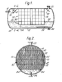
- Separator 10 shown in Figure 1 includes a vessel 12 with an inlet 14 at the upper portion of one end and directed towards a dished deflector 16 which is supported on the interior of the vessel 12 by a strut 18.
- a gas outlet 20 extends from the upper portion of vessel 12 at the end opposite inlet 14 with an inclined baffle 22 thereunder to cause gas to flow therearound to reach outlet 20.
- a slotted pipe 24 is positioned close to the bottom of the vessel 12 and is connected to a liquid outlet 26 so that all liquid discharged from the separator 10 flows through the slots on the lower side of pipe 24, through pipe 24 and out of liquid outlet 26.
- Suitable controls (not shown) are provided on liquid outlet 26 and gas outlet 20 to maintain the preselected pressure and- liquid level 28 within separator 10.
- 'A foam breaking structure 30 is positioned within the vessel 12 between inlet 14 and outlets 20 and 26 so that all foam and gas entering the separator 10 through the inlet 14 enters the structure 30.
- the foam breaking structure 30 includes two spaced apart stacks 36 and 38 of elongate modules 32, positioned horizontally within vessel 12, the longitudinal axis of each module extending transversely of the vessel 12.
- the lower tiers of modules 32 are supported at their ends on support brackets 34 which are secured within vessel 12 by welding or other suitable means.
- the remaining tiers of modules are supported on the lower tiers and substantially fill the upper interior of vessel 12.
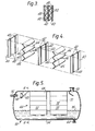
- Each module 32 includes a plurality of vertical plates 40 with spacing means such as spacer strips 42 secured to each side of plates 40 e.g. by spot welding, and divider plates 44 which are zig zag in shape, are secured in position, with their peaks 46 engaging the strips 42 and preferably spot welded thereto.
- spacing means such as spacer strips 42 secured to each side of plates 40 e.g. by spot welding
- divider plates 44 which are zig zag in shape, are secured in position, with their peaks 46 engaging the strips 42 and preferably spot welded thereto.
- the modules 32 thus provide a plurality of horizontally extending elongate passageways 48 with draining means including a plurality of vertically extending drain passages 50 (the space between peaks 46 and plates 40) and the lower surface 45 of each passageway 48 slopes downward towards a drain passage 50. It is preferred that the positioning of modules 32 be arranged so that each of passageways 48 is substantially continuous through each of sections 36 and 38.
- the separator 52 includes vessel 54 with an inlet 56 at one end directed at a deflector 58 which is supported within the vessel 54 by a strut 60.
- a gas outlet 62 and a liquid outlet 64 are the same as outlets 20 and 26 previously described, and a foam breaking structure 66 is positioned within vessel 54 so that all gas in the separator passes therethrough.
- the structure 66 is divided and is formed of two stacks 68 and 70 of longitudinally extending modules 72.
- Each module 72 in the lower tier of each section is supported on two support strips 74 which extend across the lower portion of vessel 54 substantially below liquid level 76.
- the modules extend longitudinally of the separator while in the construction of Figures 1 to 4 modules 32 extend transversely of the separator.
- the actual internal structure of the modules 72 may be of the form described above and shown in Figures 3 and 4. Alternatively, they may be of the modified form shown in Figures 7 and 8, and which again includes a plurality of vertical plates 80, spacing neans such as spacer strips 82 secured, e.g.
- Each passageway has its lower surface sloping downward towards a drain passage 88 (the space between the flats on divider plates 84 and vertical plates 80).
- Divider plates 84 nave a zig zag shape with vertical portions 90 between each inclined portion 92.
- the vertical plates and divider plates of the foam breaking structure By using relatively thin sheet material for the vertical plates and divider plates of the foam breaking structure (preferably in the range from 0.3 to 0.4 mm with 19 mm spacing of the vertical plates and spacer strips from 1.5 to 3.2 mm thick) there is a very small blocked area to the flow of gas and foam through the structure.
- vertical plates and divider plates of the foam breaking apparatus are relatively thin, the overall structure is sufficiently strong because of its honeycomb construction.
- the designs of the foam breaking apparatus provide a relatively small passageway so that there is laminar flow in each passageway and there is a maximum of surface area around each passageways There is substantial equal flow distribution resulting from the small flow area of each passageway. Also, there is adequate drainage along the sloping bottom of each passageway and the vertical plates which does not cause additional foam or re-entrainment of separated liquid.
- the improved performance of the foam breaking apparatus is believed to result from the wedging of bubbles in the lower tapered portion of each passageway and the flow through the passageway past the bubbles distorts the bubble to break its skin to thereby effect separation of the gas and liquid.
- slope of the lower surface of each of the passageways be approximately 45° and slopes from 30° to 60° from vertical are believed to be suitable for the improved performance of the present invention.
- the improved separator and foam breaking apparatus of the present invention functions efficiently in the removal of entrained liquid from flowing gas.
Landscapes
- Chemical & Material Sciences (AREA)
- Chemical Kinetics & Catalysis (AREA)
- Dispersion Chemistry (AREA)
- Separating Particles In Gases By Inertia (AREA)
- Degasification And Air Bubble Elimination (AREA)
- Disintegrating Or Milling (AREA)
Applications Claiming Priority (2)
| Application Number | Priority Date | Filing Date | Title |
|---|---|---|---|
| US16294480A | 1980-06-25 | 1980-06-25 | |
| US162944 | 1980-06-25 |
Publications (2)
| Publication Number | Publication Date |
|---|---|
| EP0043648A2 true EP0043648A2 (de) | 1982-01-13 |
| EP0043648A3 EP0043648A3 (de) | 1982-03-17 |
Family
ID=22587777
Family Applications (1)
| Application Number | Title | Priority Date | Filing Date |
|---|---|---|---|
| EP81302562A Withdrawn EP0043648A3 (de) | 1980-06-25 | 1981-06-09 | Vorrichtung zum Entschäumen in einem Gas-Flüssigkeits-Scheider |
Country Status (7)
| Country | Link |
|---|---|
| EP (1) | EP0043648A3 (de) |
| JP (1) | JPS5730519A (de) |
| KR (1) | KR830005884A (de) |
| AR (1) | AR225676A1 (de) |
| AU (1) | AU7204381A (de) |
| BR (1) | BR8103742A (de) |
| ES (1) | ES503355A0 (de) |
Cited By (5)
| Publication number | Priority date | Publication date | Assignee | Title |
|---|---|---|---|---|
| DE4114679A1 (de) * | 1991-05-06 | 1992-11-12 | Max Rhodius Gmbh & Co Weissenb | Verfahren und vorrichtung zur zerstoerung von schaum |
| FR2707890A1 (fr) * | 1993-07-20 | 1995-01-27 | Proser | Utilisation dans un séparateur triphasique d'un garnissage de colonnes de distillation et d'absorption, et séparateur triphasique équipé d'un tel garnissage. |
| WO2001051868A1 (en) * | 2000-01-07 | 2001-07-19 | Evapco International, Inc. | Drift eliminator |
| CN111729353A (zh) * | 2020-08-06 | 2020-10-02 | 中国石油化工股份有限公司 | 用于消除脱硫胺液发泡的泡沫分离装置和方法 |
| CN113996079A (zh) * | 2021-11-18 | 2022-02-01 | 重庆格林嘉科技有限公司 | 一种穿流型型材塔板的结构及安装方法 |
Families Citing this family (8)
| Publication number | Priority date | Publication date | Assignee | Title |
|---|---|---|---|---|
| JPH0771594B2 (ja) * | 1985-08-29 | 1995-08-02 | ブラザー工業株式会社 | ミシン |
| JPH0728967B2 (ja) * | 1985-08-29 | 1995-04-05 | ブラザー工業株式会社 | ミシン |
| JPH0741111B2 (ja) * | 1985-08-29 | 1995-05-10 | ブラザー工業株式会社 | 針送りミシン |
| JPH0771595B2 (ja) * | 1985-08-29 | 1995-08-02 | ブラザー工業株式会社 | ミシン |
| JPH0734836B2 (ja) * | 1985-08-29 | 1995-04-19 | ブラザー工業株式会社 | ミシン |
| JPH0734835B2 (ja) * | 1985-08-29 | 1995-04-19 | ブラザー工業株式会社 | ミシン |
| JPH0738910B2 (ja) * | 1985-09-02 | 1995-05-01 | ブラザー工業株式会社 | ミシン |
| CN116219454A (zh) * | 2023-05-11 | 2023-06-06 | 氢联(江苏)高科技有限公司 | 基于双极电极体系电解水制氢装置 |
Citations (3)
| Publication number | Priority date | Publication date | Assignee | Title |
|---|---|---|---|---|
| US2508528A (en) * | 1949-01-12 | 1950-05-23 | Mosinee Paper Mills Company | Foam separator |
| US3795091A (en) * | 1972-08-18 | 1974-03-05 | Combustion Eng | Means for separating fluids |
| DE2725811A1 (de) * | 1976-06-21 | 1977-12-29 | Riga Inc | Klaervorrichtung |
-
1981
- 1981-06-09 EP EP81302562A patent/EP0043648A3/de not_active Withdrawn
- 1981-06-12 BR BR8103742A patent/BR8103742A/pt unknown
- 1981-06-19 KR KR1019810002239A patent/KR830005884A/ko unknown
- 1981-06-22 AU AU72043/81A patent/AU7204381A/en not_active Abandoned
- 1981-06-24 JP JP9682481A patent/JPS5730519A/ja active Pending
- 1981-06-25 AR AR285860A patent/AR225676A1/es active
- 1981-06-25 ES ES503355A patent/ES503355A0/es active Granted
Patent Citations (3)
| Publication number | Priority date | Publication date | Assignee | Title |
|---|---|---|---|---|
| US2508528A (en) * | 1949-01-12 | 1950-05-23 | Mosinee Paper Mills Company | Foam separator |
| US3795091A (en) * | 1972-08-18 | 1974-03-05 | Combustion Eng | Means for separating fluids |
| DE2725811A1 (de) * | 1976-06-21 | 1977-12-29 | Riga Inc | Klaervorrichtung |
Cited By (9)
| Publication number | Priority date | Publication date | Assignee | Title |
|---|---|---|---|---|
| DE4114679A1 (de) * | 1991-05-06 | 1992-11-12 | Max Rhodius Gmbh & Co Weissenb | Verfahren und vorrichtung zur zerstoerung von schaum |
| FR2707890A1 (fr) * | 1993-07-20 | 1995-01-27 | Proser | Utilisation dans un séparateur triphasique d'un garnissage de colonnes de distillation et d'absorption, et séparateur triphasique équipé d'un tel garnissage. |
| GB2280619A (en) * | 1993-07-20 | 1995-02-08 | Procedes Et Services Proser Sa | The use of a distillation and absorption column packing in a three-phase separator |
| GB2280619B (en) * | 1993-07-20 | 1998-02-18 | Procedes Et Services Proser Sa | The use of distillation and absorption column lining in a three-phase separator and a three-phase separator equipped with such a lining |
| WO2001051868A1 (en) * | 2000-01-07 | 2001-07-19 | Evapco International, Inc. | Drift eliminator |
| US6315804B1 (en) | 2000-01-07 | 2001-11-13 | Evapco International, Inc. | Drift eliminator |
| CN111729353A (zh) * | 2020-08-06 | 2020-10-02 | 中国石油化工股份有限公司 | 用于消除脱硫胺液发泡的泡沫分离装置和方法 |
| CN111729353B (zh) * | 2020-08-06 | 2022-03-22 | 中国石油化工股份有限公司 | 用于消除脱硫胺液发泡的泡沫分离装置和方法 |
| CN113996079A (zh) * | 2021-11-18 | 2022-02-01 | 重庆格林嘉科技有限公司 | 一种穿流型型材塔板的结构及安装方法 |
Also Published As
| Publication number | Publication date |
|---|---|
| KR830005884A (ko) | 1983-09-14 |
| ES8203630A1 (es) | 1982-04-16 |
| JPS5730519A (en) | 1982-02-18 |
| AR225676A1 (es) | 1982-04-15 |
| AU7204381A (en) | 1982-01-07 |
| BR8103742A (pt) | 1982-03-02 |
| EP0043648A3 (de) | 1982-03-17 |
| ES503355A0 (es) | 1982-04-16 |
Similar Documents
| Publication | Publication Date | Title |
|---|---|---|
| EP0043648A2 (de) | Vorrichtung zum Entschäumen in einem Gas-Flüssigkeits-Scheider | |
| US4123365A (en) | Oil-water separator | |
| US4056477A (en) | Separating apparatus for clarifying liquid | |
| EP0737498B1 (de) | Gas-Flüssigkeitskontaktboden mit Ablaufelementen mit seitlichem Ablauf und dreieckigem Querschnitt | |
| CA1325179C (en) | Oil-water separator | |
| EP0155056B1 (de) | Kolonne für den Gas-Flüssgkeitsaustausch | |
| KR100547523B1 (ko) | 향상된 효율의 분별 증류 트레이 및 프로세스 | |
| US7448602B2 (en) | De-entrainment of liquid particles from gas | |
| CA1161370A (en) | Method and apparatus for supplying and distrubuting composite liquids to a laminar separation apparatus | |
| US4601731A (en) | Chevron-type mist eliminator and method | |
| TWI624296B (zh) | 液體分配器及使用方法 | |
| NL8302097A (nl) | Gas-vloeistofcontactinrichting. | |
| BR0008743B1 (pt) | separador de trÊs fases, e, processo para separar uma mistura de gÁs, àleo e Água nos constituintes gÁs, àleo e Água. | |
| US6076813A (en) | Vapor liquid contact tray with two-stage downcomer | |
| US3417015A (en) | Coalescer and separator for oily water | |
| JPS596716B2 (ja) | 分離装置 | |
| EP0001448A1 (de) | Siebboden für Dampf-Flüssigkeit-Kontakt | |
| US6746003B2 (en) | Gas-liquid contacting apparatus | |
| EP0162520A2 (de) | Gas-Flüssigkeit-Austauschkolonne | |
| US5948211A (en) | Distillation column downcomer having liquid permeable wall | |
| US4364833A (en) | Apparatus for removing substances from a mixture | |
| CA1320431C (en) | Distillation tray | |
| US2887174A (en) | Horizontal separators | |
| US3626673A (en) | Means for separating fluids | |
| EP0615776A1 (de) | Ölabscheider |
Legal Events
| Date | Code | Title | Description |
|---|---|---|---|
| PUAI | Public reference made under article 153(3) epc to a published international application that has entered the european phase |
Free format text: ORIGINAL CODE: 0009012 |
|
| PUAL | Search report despatched |
Free format text: ORIGINAL CODE: 0009013 |
|
| AK | Designated contracting states |
Designated state(s): AT BE CH DE FR GB IT LU NL SE |
|
| AK | Designated contracting states |
Designated state(s): AT BE CH DE FR GB IT LU NL SE |
|
| STAA | Information on the status of an ep patent application or granted ep patent |
Free format text: STATUS: THE APPLICATION IS DEEMED TO BE WITHDRAWN |
|
| 18D | Application deemed to be withdrawn |
Effective date: 19830225 |
|
| PGFP | Annual fee paid to national office [announced via postgrant information from national office to epo] |
Ref country code: FR Payment date: 19840614 Year of fee payment: 4 |
|
| RIN1 | Information on inventor provided before grant (corrected) |
Inventor name: ANDERSON, HOWARD W. Inventor name: PETERSON, ADRIAN |