EP0043648A2 - Separator and foam breaking element therefor - Google Patents
Separator and foam breaking element therefor Download PDFInfo
- Publication number
- EP0043648A2 EP0043648A2 EP81302562A EP81302562A EP0043648A2 EP 0043648 A2 EP0043648 A2 EP 0043648A2 EP 81302562 A EP81302562 A EP 81302562A EP 81302562 A EP81302562 A EP 81302562A EP 0043648 A2 EP0043648 A2 EP 0043648A2
- Authority
- EP
- European Patent Office
- Prior art keywords
- foam
- vessel
- plates
- vertical
- foam breaking
- Prior art date
- Legal status (The legal status is an assumption and is not a legal conclusion. Google has not performed a legal analysis and makes no representation as to the accuracy of the status listed.)
- Withdrawn
Links
Images

Classifications
-
- B—PERFORMING OPERATIONS; TRANSPORTING
- B01—PHYSICAL OR CHEMICAL PROCESSES OR APPARATUS IN GENERAL
- B01D—SEPARATION
- B01D45/00—Separating dispersed particles from gases or vapours by gravity, inertia, or centrifugal forces
- B01D45/04—Separating dispersed particles from gases or vapours by gravity, inertia, or centrifugal forces by utilising inertia
- B01D45/08—Separating dispersed particles from gases or vapours by gravity, inertia, or centrifugal forces by utilising inertia by impingement against baffle separators
-
- B—PERFORMING OPERATIONS; TRANSPORTING
- B01—PHYSICAL OR CHEMICAL PROCESSES OR APPARATUS IN GENERAL
- B01D—SEPARATION
- B01D19/00—Degasification of liquids
- B01D19/02—Foam dispersion or prevention
Definitions
- the present invention relates to an oil and gas separator and to an improved foam breaking element used in the separator.
- Prior separators which have been used to handle foaming liquids have generally included a foam breaking or liquid-separating element such as parallel plates set at an angle to allow liquid drops from ruptured bubbles to drain to the lower portion of the separation vessel such as shown in U.S. Patent Nos. 2,349,944; 3,795,091 and 3,413,779.
- foam breaking structures have included wire mesh pads (U.S. Patent No. 3,212,232) tortuous paths (U.S. Patent Nos. 1,970,783; 3,813,855 and 3,338,035) and a modular structure of sloping parallel plates (U.S. Patent No. 3,626,673).
- a foam separator comprising a vessel having an inlet, a gas outlet and a liquid outlet, and a foam breaking structure extending across the interior of said vessel between said inlet and said gas outlet, whereby all gas and foam in said vessel enters the foam breaking structure, the foam breaking structure defining a plurality of elongate passageways extending longitudinally of the vessel and a plurality of drain passages with each passageway having a lower surface sloping downwardly towards a drain passage.
- Such a separator has improved foam breaking characteristics, which breaks foam efficiently and avoids reforming of foam from the broken foam.
- the passageways are sufficiently small to provide laminar flow therethrough with a maximum of surface area and a minimum of area which forms a block to the flow.
- the invention also provides a foam breaking structure for mounting in the vessel of a foam separator, said structure comprising a plurality of vertical plates with zig zag shaped divider plates secured between each pair of vertical plates to form a plurality of horizontal elongate passageways with downwardly inclined lower surfaces, and means spacing portions of the lower ends of the lower surfaces of each passageway from the adjacent vertical plate to provide a drain passage for each passageway.
- Separator 10 shown in Figure 1 includes a vessel 12 with an inlet 14 at the upper portion of one end and directed towards a dished deflector 16 which is supported on the interior of the vessel 12 by a strut 18.
- a gas outlet 20 extends from the upper portion of vessel 12 at the end opposite inlet 14 with an inclined baffle 22 thereunder to cause gas to flow therearound to reach outlet 20.
- a slotted pipe 24 is positioned close to the bottom of the vessel 12 and is connected to a liquid outlet 26 so that all liquid discharged from the separator 10 flows through the slots on the lower side of pipe 24, through pipe 24 and out of liquid outlet 26.
- Suitable controls (not shown) are provided on liquid outlet 26 and gas outlet 20 to maintain the preselected pressure and- liquid level 28 within separator 10.
- 'A foam breaking structure 30 is positioned within the vessel 12 between inlet 14 and outlets 20 and 26 so that all foam and gas entering the separator 10 through the inlet 14 enters the structure 30.
- the foam breaking structure 30 includes two spaced apart stacks 36 and 38 of elongate modules 32, positioned horizontally within vessel 12, the longitudinal axis of each module extending transversely of the vessel 12.
- the lower tiers of modules 32 are supported at their ends on support brackets 34 which are secured within vessel 12 by welding or other suitable means.
- the remaining tiers of modules are supported on the lower tiers and substantially fill the upper interior of vessel 12.
- Each module 32 includes a plurality of vertical plates 40 with spacing means such as spacer strips 42 secured to each side of plates 40 e.g. by spot welding, and divider plates 44 which are zig zag in shape, are secured in position, with their peaks 46 engaging the strips 42 and preferably spot welded thereto.
- spacing means such as spacer strips 42 secured to each side of plates 40 e.g. by spot welding
- divider plates 44 which are zig zag in shape, are secured in position, with their peaks 46 engaging the strips 42 and preferably spot welded thereto.
- the modules 32 thus provide a plurality of horizontally extending elongate passageways 48 with draining means including a plurality of vertically extending drain passages 50 (the space between peaks 46 and plates 40) and the lower surface 45 of each passageway 48 slopes downward towards a drain passage 50. It is preferred that the positioning of modules 32 be arranged so that each of passageways 48 is substantially continuous through each of sections 36 and 38.
- the separator 52 includes vessel 54 with an inlet 56 at one end directed at a deflector 58 which is supported within the vessel 54 by a strut 60.
- a gas outlet 62 and a liquid outlet 64 are the same as outlets 20 and 26 previously described, and a foam breaking structure 66 is positioned within vessel 54 so that all gas in the separator passes therethrough.
- the structure 66 is divided and is formed of two stacks 68 and 70 of longitudinally extending modules 72.
- Each module 72 in the lower tier of each section is supported on two support strips 74 which extend across the lower portion of vessel 54 substantially below liquid level 76.
- the modules extend longitudinally of the separator while in the construction of Figures 1 to 4 modules 32 extend transversely of the separator.
- the actual internal structure of the modules 72 may be of the form described above and shown in Figures 3 and 4. Alternatively, they may be of the modified form shown in Figures 7 and 8, and which again includes a plurality of vertical plates 80, spacing neans such as spacer strips 82 secured, e.g.
- Each passageway has its lower surface sloping downward towards a drain passage 88 (the space between the flats on divider plates 84 and vertical plates 80).
- Divider plates 84 nave a zig zag shape with vertical portions 90 between each inclined portion 92.
- the vertical plates and divider plates of the foam breaking structure By using relatively thin sheet material for the vertical plates and divider plates of the foam breaking structure (preferably in the range from 0.3 to 0.4 mm with 19 mm spacing of the vertical plates and spacer strips from 1.5 to 3.2 mm thick) there is a very small blocked area to the flow of gas and foam through the structure.
- vertical plates and divider plates of the foam breaking apparatus are relatively thin, the overall structure is sufficiently strong because of its honeycomb construction.
- the designs of the foam breaking apparatus provide a relatively small passageway so that there is laminar flow in each passageway and there is a maximum of surface area around each passageways There is substantial equal flow distribution resulting from the small flow area of each passageway. Also, there is adequate drainage along the sloping bottom of each passageway and the vertical plates which does not cause additional foam or re-entrainment of separated liquid.
- the improved performance of the foam breaking apparatus is believed to result from the wedging of bubbles in the lower tapered portion of each passageway and the flow through the passageway past the bubbles distorts the bubble to break its skin to thereby effect separation of the gas and liquid.
- slope of the lower surface of each of the passageways be approximately 45° and slopes from 30° to 60° from vertical are believed to be suitable for the improved performance of the present invention.
- the improved separator and foam breaking apparatus of the present invention functions efficiently in the removal of entrained liquid from flowing gas.
Landscapes
- Chemical & Material Sciences (AREA)
- Chemical Kinetics & Catalysis (AREA)
- Dispersion Chemistry (AREA)
- Separating Particles In Gases By Inertia (AREA)
- Disintegrating Or Milling (AREA)
- Degasification And Air Bubble Elimination (AREA)
Abstract
Description
- The present invention relates to an oil and gas separator and to an improved foam breaking element used in the separator.
- Prior separators which have been used to handle foaming liquids have generally included a foam breaking or liquid-separating element such as parallel plates set at an angle to allow liquid drops from ruptured bubbles to drain to the lower portion of the separation vessel such as shown in U.S. Patent Nos. 2,349,944; 3,795,091 and 3,413,779. Other foam breaking structures have included wire mesh pads (U.S. Patent No. 3,212,232) tortuous paths (U.S. Patent Nos. 1,970,783; 3,813,855 and 3,338,035) and a modular structure of sloping parallel plates (U.S. Patent No. 3,626,673).
- According to the present invention we provide a foam separator comprising a vessel having an inlet, a gas outlet and a liquid outlet, and a foam breaking structure extending across the interior of said vessel between said inlet and said gas outlet, whereby all gas and foam in said vessel enters the foam breaking structure, the foam breaking structure defining a plurality of elongate passageways extending longitudinally of the vessel and a plurality of drain passages with each passageway having a lower surface sloping downwardly towards a drain passage.
- Such a separator has improved foam breaking characteristics, which breaks foam efficiently and avoids reforming of foam from the broken foam.
- Advantageously the passageways are sufficiently small to provide laminar flow therethrough with a maximum of surface area and a minimum of area which forms a block to the flow.
- The invention also provides a foam breaking structure for mounting in the vessel of a foam separator, said structure comprising a plurality of vertical plates with zig zag shaped divider plates secured between each pair of vertical plates to form a plurality of horizontal elongate passageways with downwardly inclined lower surfaces, and means spacing portions of the lower ends of the lower surfaces of each passageway from the adjacent vertical plate to provide a drain passage for each passageway.
- In order that the present invention will be more fully understood, the following description is given, merely by way of example, reference being made to the accompanying drawings, wherein:
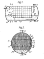
- Figure 1 is a longitudinal sectional view of one embodiment of foam separator according to the present invention;
- Figure 2 is a transverse section taken along line 2-2 in Figure 1;
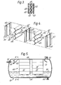
- Figure 3 is an enlarged end elevation of a portion of the form of foam breaking structure of the separator;
- Figure 4 is an exploded perspective view of the elements of the portion of the foam breaking structure of Figure 3;
- Figure 5 is a view similar to Figure I with a different modular structure of the foam breaking apparatus:
- Figure 6 is a transverse section taken along line 6-6 in Figure 5;
- Figure 7 is an enlarged end elevation of a portion of a modified form of foam breaking structure of the separator; and
- Figure 8 is an exploded perspective view of the elements of the portion of the foam breaking structure shown in Figure 7.
-
Separator 10 shown in Figure 1 includes avessel 12 with aninlet 14 at the upper portion of one end and directed towards adished deflector 16 which is supported on the interior of thevessel 12 by astrut 18. Agas outlet 20 extends from the upper portion ofvessel 12 at the end oppositeinlet 14 with an inclined baffle 22 thereunder to cause gas to flow therearound to reachoutlet 20. Aslotted pipe 24 is positioned close to the bottom of thevessel 12 and is connected to aliquid outlet 26 so that all liquid discharged from theseparator 10 flows through the slots on the lower side ofpipe 24, throughpipe 24 and out ofliquid outlet 26. Suitable controls (not shown) are provided onliquid outlet 26 andgas outlet 20 to maintain the preselected pressure and-liquid level 28 withinseparator 10. 'Afoam breaking structure 30 is positioned within thevessel 12 betweeninlet 14 andoutlets separator 10 through theinlet 14 enters thestructure 30. - The
foam breaking structure 30 includes two spacedapart stacks elongate modules 32, positioned horizontally withinvessel 12, the longitudinal axis of each module extending transversely of thevessel 12. The lower tiers ofmodules 32 are supported at their ends onsupport brackets 34 which are secured withinvessel 12 by welding or other suitable means. The remaining tiers of modules are supported on the lower tiers and substantially fill the upper interior ofvessel 12. - Each
module 32, as shown in Figures 3 and 4, includes a plurality ofvertical plates 40 with spacing means such asspacer strips 42 secured to each side ofplates 40 e.g. by spot welding, anddivider plates 44 which are zig zag in shape, are secured in position, with theirpeaks 46 engaging thestrips 42 and preferably spot welded thereto. - The
modules 32 thus provide a plurality of horizontally extendingelongate passageways 48 with draining means including a plurality of vertically extending drain passages 50 (the space betweenpeaks 46 and plates 40) and thelower surface 45 of eachpassageway 48 slopes downward towards adrain passage 50. It is preferred that the positioning ofmodules 32 be arranged so that each ofpassageways 48 is substantially continuous through each ofsections - In the construction of Figures 5 to 8, the
separator 52 includesvessel 54 with aninlet 56 at one end directed at adeflector 58 which is supported within thevessel 54 by a strut 60. Agas outlet 62 and aliquid outlet 64 are the same asoutlets foam breaking structure 66 is positioned withinvessel 54 so that all gas in the separator passes therethrough. - The
structure 66 is divided and is formed of twostacks modules 72. Eachmodule 72 in the lower tier of each section is supported on two support strips 74 which extend across the lower portion ofvessel 54 substantially belowliquid level 76. Thus, in this modified form of separator, the modules extend longitudinally of the separator while in the construction of Figures 1 to 4modules 32 extend transversely of the separator. The actual internal structure of themodules 72 may be of the form described above and shown in Figures 3 and 4. Alternatively, they may be of the modified form shown in Figures 7 and 8, and which again includes a plurality ofvertical plates 80, spacing neans such asspacer strips 82 secured, e.g. by spot welding to both sides ofplates 80 anddivider plates 84 secured betweenplates 80, define a plurality of horizontally extendingelongate passageways 86. Each passageway has its lower surface sloping downward towards a drain passage 88 (the space between the flats ondivider plates 84 and vertical plates 80).Divider plates 84 nave a zig zag shape withvertical portions 90 between eachinclined portion 92. - By using relatively thin sheet material for the vertical plates and divider plates of the foam breaking structure (preferably in the range from 0.3 to 0.4 mm with 19 mm spacing of the vertical plates and spacer strips from 1.5 to 3.2 mm thick) there is a very small blocked area to the flow of gas and foam through the structure. Even though vertical plates and divider plates of the foam breaking apparatus are relatively thin, the overall structure is sufficiently strong because of its honeycomb construction. The designs of the foam breaking apparatus provide a relatively small passageway so that there is laminar flow in each passageway and there is a maximum of surface area around each passageways There is substantial equal flow distribution resulting from the small flow area of each passageway. Also, there is adequate drainage along the sloping bottom of each passageway and the vertical plates which does not cause additional foam or re-entrainment of separated liquid.
- The improved performance of the foam breaking apparatus is believed to result from the wedging of bubbles in the lower tapered portion of each passageway and the flow through the passageway past the bubbles distorts the bubble to break its skin to thereby effect separation of the gas and liquid.
- It is preferred that the slope of the lower surface of each of the passageways be approximately 45° and slopes from 30° to 60° from vertical are believed to be suitable for the improved performance of the present invention.
- It is also believed that the improved separator and foam breaking apparatus of the present invention functions efficiently in the removal of entrained liquid from flowing gas.
Claims (10)
Applications Claiming Priority (2)
| Application Number | Priority Date | Filing Date | Title |
|---|---|---|---|
| US16294480A | 1980-06-25 | 1980-06-25 | |
| US162944 | 1980-06-25 |
Publications (2)
| Publication Number | Publication Date |
|---|---|
| EP0043648A2 true EP0043648A2 (en) | 1982-01-13 |
| EP0043648A3 EP0043648A3 (en) | 1982-03-17 |
Family
ID=22587777
Family Applications (1)
| Application Number | Title | Priority Date | Filing Date |
|---|---|---|---|
| EP81302562A Withdrawn EP0043648A3 (en) | 1980-06-25 | 1981-06-09 | Separator and foam breaking element therefor |
Country Status (7)
| Country | Link |
|---|---|
| EP (1) | EP0043648A3 (en) |
| JP (1) | JPS5730519A (en) |
| KR (1) | KR830005884A (en) |
| AR (1) | AR225676A1 (en) |
| AU (1) | AU7204381A (en) |
| BR (1) | BR8103742A (en) |
| ES (1) | ES8203630A1 (en) |
Cited By (5)
| Publication number | Priority date | Publication date | Assignee | Title |
|---|---|---|---|---|
| DE4114679A1 (en) * | 1991-05-06 | 1992-11-12 | Max Rhodius Gmbh & Co Weissenb | Process for destruction of foam resulting from gas washing processes - comprises introducing foam into package of interwoven wires, with drain gaps through which fluid from bubbles passes, destroying foam |
| FR2707890A1 (en) * | 1993-07-20 | 1995-01-27 | Proser | Use in a three-phase separator of a packing of distillation and absorption columns, and three-phase separator equipped with such a packing. |
| WO2001051868A1 (en) * | 2000-01-07 | 2001-07-19 | Evapco International, Inc. | Drift eliminator |
| CN111729353A (en) * | 2020-08-06 | 2020-10-02 | 中国石油化工股份有限公司 | Foam separation device and method for eliminating foaming of desulfurized amine liquid |
| CN113996079A (en) * | 2021-11-18 | 2022-02-01 | 重庆格林嘉科技有限公司 | Structure and installation method of cross-flow profile tray |
Families Citing this family (8)
| Publication number | Priority date | Publication date | Assignee | Title |
|---|---|---|---|---|
| JPH0728967B2 (en) * | 1985-08-29 | 1995-04-05 | ブラザー工業株式会社 | sewing machine |
| JPH0734835B2 (en) * | 1985-08-29 | 1995-04-19 | ブラザー工業株式会社 | sewing machine |
| JPH0741111B2 (en) * | 1985-08-29 | 1995-05-10 | ブラザー工業株式会社 | Needle feed sewing machine |
| JPH0771594B2 (en) * | 1985-08-29 | 1995-08-02 | ブラザー工業株式会社 | sewing machine |
| JPH0771595B2 (en) * | 1985-08-29 | 1995-08-02 | ブラザー工業株式会社 | sewing machine |
| JPH0734836B2 (en) * | 1985-08-29 | 1995-04-19 | ブラザー工業株式会社 | sewing machine |
| JPH0738910B2 (en) * | 1985-09-02 | 1995-05-01 | ブラザー工業株式会社 | sewing machine |
| CN116219454A (en) * | 2023-05-11 | 2023-06-06 | 氢联(江苏)高科技有限公司 | Hydrogen production device based on bipolar electrode system for water electrolysis |
Family Cites Families (3)
| Publication number | Priority date | Publication date | Assignee | Title |
|---|---|---|---|---|
| US2508528A (en) * | 1949-01-12 | 1950-05-23 | Mosinee Paper Mills Company | Foam separator |
| US3795091A (en) * | 1972-08-18 | 1974-03-05 | Combustion Eng | Means for separating fluids |
| US4056477A (en) * | 1976-06-21 | 1977-11-01 | Riga, Inc. | Separating apparatus for clarifying liquid |
-
1981
- 1981-06-09 EP EP81302562A patent/EP0043648A3/en not_active Withdrawn
- 1981-06-12 BR BR8103742A patent/BR8103742A/en unknown
- 1981-06-19 KR KR1019810002239A patent/KR830005884A/en not_active Ceased
- 1981-06-22 AU AU72043/81A patent/AU7204381A/en not_active Abandoned
- 1981-06-24 JP JP9682481A patent/JPS5730519A/en active Pending
- 1981-06-25 AR AR285860A patent/AR225676A1/en active
- 1981-06-25 ES ES503355A patent/ES8203630A1/en not_active Expired
Cited By (9)
| Publication number | Priority date | Publication date | Assignee | Title |
|---|---|---|---|---|
| DE4114679A1 (en) * | 1991-05-06 | 1992-11-12 | Max Rhodius Gmbh & Co Weissenb | Process for destruction of foam resulting from gas washing processes - comprises introducing foam into package of interwoven wires, with drain gaps through which fluid from bubbles passes, destroying foam |
| FR2707890A1 (en) * | 1993-07-20 | 1995-01-27 | Proser | Use in a three-phase separator of a packing of distillation and absorption columns, and three-phase separator equipped with such a packing. |
| GB2280619A (en) * | 1993-07-20 | 1995-02-08 | Procedes Et Services Proser Sa | The use of a distillation and absorption column packing in a three-phase separator |
| GB2280619B (en) * | 1993-07-20 | 1998-02-18 | Procedes Et Services Proser Sa | The use of distillation and absorption column lining in a three-phase separator and a three-phase separator equipped with such a lining |
| WO2001051868A1 (en) * | 2000-01-07 | 2001-07-19 | Evapco International, Inc. | Drift eliminator |
| US6315804B1 (en) | 2000-01-07 | 2001-11-13 | Evapco International, Inc. | Drift eliminator |
| CN111729353A (en) * | 2020-08-06 | 2020-10-02 | 中国石油化工股份有限公司 | Foam separation device and method for eliminating foaming of desulfurized amine liquid |
| CN111729353B (en) * | 2020-08-06 | 2022-03-22 | 中国石油化工股份有限公司 | Foam separation device and method for eliminating foaming of desulfurized amine liquid |
| CN113996079A (en) * | 2021-11-18 | 2022-02-01 | 重庆格林嘉科技有限公司 | Structure and installation method of cross-flow profile tray |
Also Published As
| Publication number | Publication date |
|---|---|
| ES503355A0 (en) | 1982-04-16 |
| AU7204381A (en) | 1982-01-07 |
| AR225676A1 (en) | 1982-04-15 |
| EP0043648A3 (en) | 1982-03-17 |
| BR8103742A (en) | 1982-03-02 |
| JPS5730519A (en) | 1982-02-18 |
| ES8203630A1 (en) | 1982-04-16 |
| KR830005884A (en) | 1983-09-14 |
Similar Documents
| Publication | Publication Date | Title |
|---|---|---|
| EP0043648A2 (en) | Separator and foam breaking element therefor | |
| US4123365A (en) | Oil-water separator | |
| US4056477A (en) | Separating apparatus for clarifying liquid | |
| EP0737498B1 (en) | Gas-liquid contacting tray with side discharging triangular downcomers | |
| EP0155056B1 (en) | Gas/liquid contacting column | |
| CA1325179C (en) | Oil-water separator | |
| US4202778A (en) | Separating device | |
| CA1161370A (en) | Method and apparatus for supplying and distrubuting composite liquids to a laminar separation apparatus | |
| TWI624296B (en) | Liquid distributor and method of use | |
| US4601731A (en) | Chevron-type mist eliminator and method | |
| US20070023937A1 (en) | De-entrainment of liquid particles from gas | |
| JPS6116481B2 (en) | ||
| KR20030009508A (en) | Increased efficiency fractional distillation tray and process | |
| US6076813A (en) | Vapor liquid contact tray with two-stage downcomer | |
| US4591367A (en) | Horizontal gas/liquid separator | |
| CA1134284A (en) | Separation device | |
| JPS596716B2 (en) | Separation device | |
| US3951818A (en) | Chevron clarifier | |
| EP0001448A1 (en) | Vapor-liquid contacting tray | |
| US6746003B2 (en) | Gas-liquid contacting apparatus | |
| EP0162520A2 (en) | Gas/liquid contacting column | |
| US5948211A (en) | Distillation column downcomer having liquid permeable wall | |
| US4364833A (en) | Apparatus for removing substances from a mixture | |
| CA1320431C (en) | Distillation tray | |
| US2887174A (en) | Horizontal separators |
Legal Events
| Date | Code | Title | Description |
|---|---|---|---|
| PUAI | Public reference made under article 153(3) epc to a published international application that has entered the european phase |
Free format text: ORIGINAL CODE: 0009012 |
|
| PUAL | Search report despatched |
Free format text: ORIGINAL CODE: 0009013 |
|
| AK | Designated contracting states |
Designated state(s): AT BE CH DE FR GB IT LU NL SE |
|
| AK | Designated contracting states |
Designated state(s): AT BE CH DE FR GB IT LU NL SE |
|
| STAA | Information on the status of an ep patent application or granted ep patent |
Free format text: STATUS: THE APPLICATION IS DEEMED TO BE WITHDRAWN |
|
| 18D | Application deemed to be withdrawn |
Effective date: 19830225 |
|
| PGFP | Annual fee paid to national office [announced via postgrant information from national office to epo] |
Ref country code: FR Payment date: 19840614 Year of fee payment: 4 |
|
| RIN1 | Information on inventor provided before grant (corrected) |
Inventor name: ANDERSON, HOWARD W. Inventor name: PETERSON, ADRIAN |