EP0041690B2 - Machine-outil à plusieurs étages travaillant le métal par formage - Google Patents
Machine-outil à plusieurs étages travaillant le métal par formage Download PDFInfo
- Publication number
- EP0041690B2 EP0041690B2 EP81104252A EP81104252A EP0041690B2 EP 0041690 B2 EP0041690 B2 EP 0041690B2 EP 81104252 A EP81104252 A EP 81104252A EP 81104252 A EP81104252 A EP 81104252A EP 0041690 B2 EP0041690 B2 EP 0041690B2
- Authority
- EP
- European Patent Office
- Prior art keywords
- axis
- blank
- forming machine
- pin
- station
- Prior art date
- Legal status (The legal status is an assumption and is not a legal conclusion. Google has not performed a legal analysis and makes no representation as to the accuracy of the status listed.)
- Expired
Links
Images


Classifications
-
- B—PERFORMING OPERATIONS; TRANSPORTING
- B21—MECHANICAL METAL-WORKING WITHOUT ESSENTIALLY REMOVING MATERIAL; PUNCHING METAL
- B21J—FORGING; HAMMERING; PRESSING METAL; RIVETING; FORGE FURNACES
- B21J13/00—Details of machines for forging, pressing, or hammering
- B21J13/08—Accessories for handling work or tools
-
- B—PERFORMING OPERATIONS; TRANSPORTING
- B21—MECHANICAL METAL-WORKING WITHOUT ESSENTIALLY REMOVING MATERIAL; PUNCHING METAL
- B21K—MAKING FORGED OR PRESSED METAL PRODUCTS, e.g. HORSE-SHOES, RIVETS, BOLTS OR WHEELS
- B21K27/00—Handling devices, e.g. for feeding, aligning, discharging, Cutting-off means; Arrangement thereof
- B21K27/02—Feeding devices for rods, wire, or strips
- B21K27/04—Feeding devices for rods, wire, or strips allowing successive working steps
Definitions
- the present invention relates to a multi-stage forming machine for chipless forming of blanks, according to the first part of claim 1.
- a multi-stage forming machine for chipless forming of blanks, according to the first part of claim 1.
- Such a machine is known from DE-B No. 1627519.
- the starting material is pulled in the direction of the press axis next to the press slide against a stop and sheared off with a shear knife.
- the shear carriage also serves as a feed of the sheared blank in front of the 1st forming station or a loading station, the longitudinal axis of the blank remaining parallel to the press axis.
- the device is also to be distinguished from the known designs by its structural simplicity.
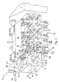
- a lower die holder 2 with four recesses for receiving dies is attached to a press frame 1.
- Four die holder covers 3, 4, 5 and 6 are attached above it.
- Tongs carrier boxes (guide parts) 7a, 7b are located above and below these die holders.
- These pliers carrier boxes are each attached to a shaft (main shaft) 8 by means of a clamp connection and have the task of connecting the pliers to be described with the shafts 8, of which only the upper one is visible.
- Each of these shafts 8 is rotatably and longitudinally displaceably mounted in the press frame 1 and both are in exactly the same direction in the direction of arrow A or in opposite directions in the direction of arrow B, with A representing a translatory movement in the direction of the shaft axis 93 and B an angular movement about the same axis.
- a drive mechanism transmits to these shafts the movement which is necessary for transporting the compacts from one forming station to the next and for the empty return.
- This sequence of movements takes place in two parts: on the one hand as a transverse transport movement of the compacts from one die to the other (arrow A), on the other hand for opening and closing the pliers, or for gripping or releasing the compacts (swiveling movement around shaft 8, arrow B).
- Three pairs of pliers 9, 10, 11 are releasably attached to the front of the pliers carrier box 7a, 7b. While the pairs of pliers 10 and 11 now correspond to the known shape and are provided with fixed lower grippers 12 and spring-supported upper grippers 13, the first pair of pliers was replaced by a rotatable device (pliers carrier) 9a and 9b, respectively.
- the wire or rod is retracted in the axis 14 in the direction of the arrow against an adjustable stop (not shown), which adjusts the section length, and is sheared off with the shear knife 15 shown schematically.
- the sheared section is held in place by a device (not shown) on the shear knife 15 and brought to the first station.
- this is not the first deforming station, but a pure holding station, in which the section is held until it is taken over by the tongs 9a / 9b.
- a protruding from the first punch tool of the advancing press slide and resiliently supported holding pin 16 presses the sheared blank 17 out of the holding device on the shear knife against a stop pin 18 which was installed in the opening provided instead of a first die.
- the holding pin 16 holds the blank until the pair of pliers (pliers carrier), designated as a whole by 9, which has moved to the left end position with the transverse transport carriers, has gripped the latter by the pivoting movements B, while the invisible one, which is to be thought in front of the drawing plane Press carriage goes back to its rear position, and thus also pulls back the holding pin 16.
- the cross transport beams are now moved to their right end position.
- an upper and a lower gripper 19 or 20 which is rotatable in the bearing holders 22a and 22b, rotates through 90 ° about the vertical axis 21.
- This gripping movement is obtained by a spatial, ie three-dimensionally movable two-stroke gear 23a and 23b , which has the function of a guide gear and whose task is to inevitably guide the pliers 9 holding the blank 17 during their translation movement in such a way that on the one hand there is a rotation of the blank by 90 ° with respect to the vertical axis 21 and on the other hand this rotation to the translatory movement is coordinated in such a way that a large part of the angular movement takes place in the first half of the translatory tong path.
- the aim of this is to ensure that the guide gear required for its movement takes up the smallest possible space and, in particular, to the adjacent die housings that there are no, or only insignificant, design changes, such as, for example, B. recesses must be made.
- Each of the spatial two-stroke gearbox is composed of a link 24 and a coupling 25.
- the link 24 has a bearing bush at its rear end, which is rotatably mounted on a fixed pin, according to FIG. 5, about the axis 28.
- the connection between the link 24 and the coupling 25 forms a ball joint 30, while the coupling 25 has at its other end a pivot which in the part (transmission member) 9c (top) or 9d (bottom) of the device 9 which can be pivoted about the axis 21 engages and is rotatably supported there about the axis 29a (top) or 29b (bottom).
- Fig. 2 shows schematically the representation of the sequence of movements of the spatial two-stroke gear, projected onto a horizontal plane.
- the solid lines show the position of the guide gear when the transverse transport is in the right end position, i.e. the compact 17 is rotated by 90 ° in front of the forming station, while the left end position is shown in broken lines, so the compact is still in position how it was brought into the charging station by the clipper.
- the handlebar 24 is thus rotatably attached at one end to a fixed bearing about the vertical axis 28. This enables the other end, which is connected to the coupling 25 by the ball joint 30, to move on an arc 31, dash-dotted in FIG. 2.
- the coupling 25 is provided at its gripper-side end opposite the ball joint 30 with a pivot pin which engages in the part 9c or 9d of the device 9 which can be rotated about the vertical axis 21 and is rotatable about the axis 29a / 29b.
- the pliers carrier which is guided in a straight line by the shaft 8, now moves from the left end position (the two-stroke transmission 23 is therefore in the position shown in broken lines) into the right end position (drawn out in FIG. 2), the pliers rotation axis moves from 21 'along the Line 32 to 21, and the ball joint point follows the circular arc 31 from 30 'to 30.
- the coupling 25, which is guided on the one hand on the arc 31 and on the other hand on the straight line 32, is rotated by 90 °, at least as long as the gear (as shown in Fig. 2) moves in the projection plane, represented by the distance 25a 'and 25a. Since the pivot pin, which forms the axis 29 and is fastened in the coupling 25, engages in the device 9 which can be rotated about the vertical axis 21, it is thus also rotated through 90 °.
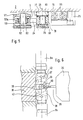
- FIG. 6 shows the takeover of the rotated blank 33 by the spring pin 35 installed in the second punch 34 of the press slide and the die 36.
- the press slide 34 By moving the press slide 34 forward, the blank 33 is pressed out of the pliers jaws 37, 38 by the spring pin or pins 35 until the blank rests on the engraving 39 of the die.
- the shape of the pliers jaws 37, 38 is designed such that the blank can be ejected on the die side, but is guided until it is pressed against the engraving 39 of the die 36, while it rests on a shoulder 40 on the other side .
- the upper and lower pliers carrier box pivot about the shaft 8 by a certain amount (arrow B, Fig.
- Fig. 6 shows the jaw design for the largest (dash-dotted) and the smallest blank.
- the areas between the pads 41 (Fig. 4) are slanted to prevent dirt from accumulating.
- FIG. 4 shows a central vertical section through the pair of pliers 9.
- a bearing holder 43 is screwed onto the plier carrier box 7b by means of screws 44.
- the bearing holder 43 there are two plain bearing bushes 45 in which the rotating part (transmission member) 46 of the pliers unit is mounted.
- the axial position results from a shoulder 47 and a cover 48 screwed onto the lower end of the rotating part 46.
- the coupling 25 could encompass the pin 50 in a fork-like manner from both end faces. To rule out the risk of contamination, the coupling 25 engages as u. a.
- FIG. 1 shows, only from one side on the pin 50 to which it is attached by known means. Also firmly connected to the coupling 25 is a housing 51 which has a slot s to the rear (FIG. 5) and which serves as a holder for the ball joint pin 52. A ball 53 surrounds the ball joint pin 52. The handlebar is provided with a spherical cap 53a, which surrounds the ball 53 and can be rotated relative to it in a known manner.
- the jaw holder 55 has a slot 56, so that the jaw holder 55 engages over the two surfaces 54. This ensures the correct position of the jaw holder 55 relative to the rotating part 46 and the two parts are secured against relative rotation.
- a clamping sleeve 57 is used, by means of which the rotating part 46 and the jaw holder 55 fixed, i. H. be connected torsionally rigid.
- an adjusting screw 58 is used, which is screwed into an eyelet 59 which is firmly connected to the clamping sleeve 57, and which can be rotated after loosening a locking nut 60 and a clamping screw 61, and thereby the height of the stop 62 on the jaw holder 55 is molded, adjusted.
- the pliers jaw 63 which is used to hold the blank 64, is screwed onto the pliers jaw carrier with a screw 65, and corresponding guide surfaces ensure the correct position.
- the upper half of the pliers is constructed in principle the same as the lower, but has the difference that it is in the axial, ie. H. is supported in the vertical direction. Therefore, the upper jaw holder 66 with a sleeve 67, which is only coupled to the rotating part 68 with a clamp connection, is mounted in a sleeve 69 so as to be longitudinally displaceable.
- a spring 70 which is guided in a central bore of the jaw holder, presses it and thus the jaw 71 onto the blank 64.
- the spring travel X is set by turning a screw 72 after loosening a locking nut 73.
- a cross pin 96 is installed at the upper end of the jaw holder 66.
- the attachment to the upper jaw holder is the same as below, as is the rotary drive.
- the die holder 2 So that there is space between the die holder 2 and the lower pliers box support 7b for the rotary drive 23a / 23b, the die holder 2 must be provided with a recess 74 in the area of the 1st die (FIGS. 1 and 4).
- FIG. 5 shows, using a vertical section, the fixed bearing of the lower spatial two-stroke rotary drive.
- a console 75 is screwed to the die holder 2 at the bottom. With this console 75, which serves as an assembly aid, a holding plate 76 is detachably connected. A bearing journal 77 is rigidly connected to this holding plate 76.
- the link 24 provided with a bearing bush 78 is placed over the bearing pin 77 and secured with a cover 79 screwed onto the bearing pin 77.
- the bearing bush 78 is provided with a seal 80 at the top, while the bearing is closed at the bottom with a cover 81.
- This mounting allows the handlebar 24 to rotate about the axis 28 (Fig. 2).
- the ball joint pin 52 is fastened to the housing 51 with a conical pin 82, which is firmly connected to the coupling 25.
- the upper fixed bearing is mounted on a bracket 26 (Fig. 1). This is pressed onto the die holder cover 3 by a hydraulically actuated cylinder 27, which at the same time serves to pivot the upper tong holder box 7a, and is thus held stationary.
- the stop 18 In this device, it is a condition that when the blank has been pushed into the 1st station up to the stop 18 (FIG. 1), its center or center of gravity is located in the axis of rotation 21 of the pair of pliers 9. This means that if the section length is changed during the shearing process, the depth of penetration into the 1st station must also change. H. the stop 18 must be adjusted. If the section is shortened by dimension a, the stop must be moved forward by dimension a / 2. According to the present example, the stop 18 is mechanically or electrically coupled to the section length adjustment so that the position of the stop 18 always corresponds to the section length and the center of gravity of the blank is always the same distance from the front of the die as the axis of rotation 21 of the rotating device 9.
- Fig. 3 shows the sequence of movements of the rotating blank.
- the blank 83 lies against the stop pin 18, which in one instead of the normal forming insert 84 inserted into the opening provided for this purpose.
- the blank is also started to be turned immediately.
- the filler 84 is set back from the normal die front edge to leave room for the long blank. It can be seen from the figure that the rotating blank 85 would collide with the die holder 2. A recess 86 is therefore arranged there.
- the die 87 inserted in the second station also has a small adjustment 88.
- This adjustment 88 can be kept so low because the blank, because of the choice of the spatial two-stroke as a rotary drive and because of the geometrical arrangement of the joints, before going through half the translational stroke by much more than 45 °, in the present example by about 60 °, is rotated. As a result, the die 87 experiences practically no restriction and is therefore a fully-fledged forming die.
- the upper tong holder box 7a can be swung up around the shaft 8 (FIG. 1).
- the shaft 8 is uncoupled from the drive mechanism, not shown, and pushed beyond the left starting position (1st pliers before 1st die) until the projecting profile piece 90, which is a continuation of the shaft 92, on which the bearing bracket 26 is attached, and which in is mounted on the same axis 93 as shaft 8, projects into the matching opening 91.
- the upper tong holder box 7a can be pivoted up with the cylinder 27.
- the bearing bracket 26 rotates with it, including the rotary drive 23.
- the upper tong support box 7a can be pivoted up without problems.
- the rotatable device 9 can be replaced by an original pair of pliers (version 10, 11, Fig. 1).
- the rotary drive 23 remains on the pliers units, i.e. H. the upper one is separated from the bearing bracket 26 by loosening the screws 95, while the lower rotary drive is separated from the guide device by loosening the screws 95 (FIG. 5). This ensures a quick changeover for forming conventional parts.
- a holding station I was switched on between the shearing station and the first forming station II, the main function of which is to hold the sheared section until it has been gripped securely by the pliers 19 and 20.
- the turning device described could also very generally between any two neighboring stations, for. B. between the forming stations 111 and IV, are attached.
- the exemplary embodiment shows a multi-stage forming machine with horizontal press ram movement.
- the principle claimed can also be applied equally to vertical machines.
- both pliers 19 and 20 are coupled to a guide gear 23. But it would also be possible to inevitably guide only one pair of pliers over such a guide gear and to arrange the other loosely rotatable.
Claims (8)
Priority Applications (1)
| Application Number | Priority Date | Filing Date | Title |
|---|---|---|---|
| AT81104252T ATE6834T1 (de) | 1980-06-10 | 1981-06-03 | Mehrstufige umformmaschine. |
Applications Claiming Priority (2)
| Application Number | Priority Date | Filing Date | Title |
|---|---|---|---|
| DE3021695 | 1980-06-10 | ||
| DE3021695 | 1980-06-10 |
Publications (4)
| Publication Number | Publication Date |
|---|---|
| EP0041690A2 EP0041690A2 (fr) | 1981-12-16 |
| EP0041690A3 EP0041690A3 (en) | 1982-03-17 |
| EP0041690B1 EP0041690B1 (fr) | 1984-03-28 |
| EP0041690B2 true EP0041690B2 (fr) | 1988-11-30 |
Family
ID=6104229
Family Applications (1)
| Application Number | Title | Priority Date | Filing Date |
|---|---|---|---|
| EP81104252A Expired EP0041690B2 (fr) | 1980-06-10 | 1981-06-03 | Machine-outil à plusieurs étages travaillant le métal par formage |
Country Status (5)
| Country | Link |
|---|---|
| US (1) | US4430882A (fr) |
| EP (1) | EP0041690B2 (fr) |
| JP (1) | JPS6018266B2 (fr) |
| AT (1) | ATE6834T1 (fr) |
| DE (1) | DE3162864D1 (fr) |
Families Citing this family (10)
| Publication number | Priority date | Publication date | Assignee | Title |
|---|---|---|---|---|
| JP2652850B2 (ja) * | 1985-10-11 | 1997-09-10 | オ−ビタル、エンジン、カンパニ−、プロプライエタリ、リミテッド | 燃料計量方法及びその装置 |
| EP0559991B1 (fr) * | 1992-02-11 | 1995-05-03 | Hatebur Umformmaschinen AG | Dispositif de retournement pour presses à transfert transversal |
| US5498895A (en) * | 1993-07-07 | 1996-03-12 | Actel Corporation | Process ESD protection devices for use with antifuses |
| JPH0984982A (ja) * | 1995-09-20 | 1997-03-31 | Kanto Sheet Seisakusho:Kk | ミシンの糸切れ検出装置 |
| DE19545570A1 (de) | 1995-12-07 | 1997-06-12 | Schuler Pressen Gmbh & Co | Transfereinrichtung für Mehrstationenpressen |
| WO2003080875A2 (fr) * | 2002-03-26 | 2003-10-02 | Nedschroef Herentals N.V. | Dispositif permettant de transferer des elements de fil |
| KR101712957B1 (ko) * | 2016-05-26 | 2017-03-22 | 대한메탈(주) | 형상물의 방향전환 기능을 구비한 냉간단조포머장치 |
| US10857585B2 (en) * | 2016-05-26 | 2020-12-08 | Daido Steel Co., Ltd. | Transfer device of multistage forging press machine |
| JP6096360B1 (ja) * | 2016-08-12 | 2017-03-15 | 旭サナック株式会社 | ワーク姿勢変更装置および多工程圧造機 |
| KR102351104B1 (ko) * | 2017-11-29 | 2022-01-14 | 한국과학기술원 | 양성자-붕소 핵반응을 이용한 발전 시스템 |
Family Cites Families (11)
| Publication number | Priority date | Publication date | Assignee | Title |
|---|---|---|---|---|
| FR1210969A (fr) * | 1957-09-25 | 1960-03-11 | Waterbury Farrel Foundry Co | Mécanisme de transfert pour machines à façonner des têtes et machines similaires |
| US3165766A (en) * | 1961-08-29 | 1965-01-19 | Nat Machinery Co | Transfer for metal forming machine |
| DE1189359B (de) * | 1963-02-26 | 1965-03-18 | Nedschroef Octrooi Maats | Transporteinrichtung an einer Mehrfachdruckpresse |
| US3217343A (en) * | 1963-05-06 | 1965-11-16 | Lamson & Sessions Co | Transfer mechanism with rotatable work engaging means |
| US3466917A (en) * | 1966-10-19 | 1969-09-16 | Nat Machinery Co The | Method and apparatus for forging blanks |
| DE2318449C2 (de) * | 1973-04-12 | 1982-09-09 | L. Schuler GmbH, 7320 Göppingen | Zu- und Abführvorrichtung für tafel- oder bandförmige Werkstücke an Pressen |
| US3965718A (en) * | 1973-07-23 | 1976-06-29 | The National Machinery Company | Transfer mechanism |
| BE827766R (fr) * | 1974-11-18 | 1975-07-31 | Mecanisme de transfert | |
| DE2715966C3 (de) * | 1977-04-09 | 1980-03-27 | Hatebur Umformmaschinen Ag, Basel (Schweiz) | Einrichtung zum automatischen Transport von Werkstücken an mehrstufigen Quertransportpressen |
| DE2800828A1 (de) * | 1978-01-10 | 1979-07-12 | Krupp Gmbh | Vorrichtung zum wenden von werkstuecken |
| US4351180A (en) * | 1980-06-30 | 1982-09-28 | The National Machinery Company | Workpiece turning transfer |
-
1981
- 1981-05-29 US US06/268,206 patent/US4430882A/en not_active Expired - Fee Related
- 1981-05-30 JP JP56083689A patent/JPS6018266B2/ja not_active Expired
- 1981-06-03 DE DE8181104252T patent/DE3162864D1/de not_active Expired
- 1981-06-03 AT AT81104252T patent/ATE6834T1/de not_active IP Right Cessation
- 1981-06-03 EP EP81104252A patent/EP0041690B2/fr not_active Expired
Also Published As
| Publication number | Publication date |
|---|---|
| EP0041690A3 (en) | 1982-03-17 |
| ATE6834T1 (de) | 1984-04-15 |
| JPS6018266B2 (ja) | 1985-05-09 |
| EP0041690A2 (fr) | 1981-12-16 |
| EP0041690B1 (fr) | 1984-03-28 |
| US4430882A (en) | 1984-02-14 |
| JPS5725238A (en) | 1982-02-10 |
| DE3162864D1 (en) | 1984-05-03 |
Similar Documents
| Publication | Publication Date | Title |
|---|---|---|
| DE602005005575T2 (de) | Biegeform mit einem Schraubstock zum Einspannen eines länglichen Elementes in einer Biegemaschine | |
| DE3434009C2 (fr) | ||
| DE4330683C2 (de) | Falzvorrichtung | |
| DE3120772A1 (de) | Schweissvorrichtung fuer einen kraftfahrzeugkoerper | |
| DE19621658C2 (de) | Bearbeitungsmaschine für plattenförmige Werkstücke, insbesondere zur Erzeugung von gebogenen Rändern an Blechteilen | |
| DE2708457C2 (de) | Transportmechanismus für Schmiedemaschinen | |
| DE2359918C3 (de) | Vorrichtung zum Zu- und Abführen von aus flächigem Material bestehenden Werkstücken | |
| DE2930006A1 (de) | Werkstueckbeschickungsvorrichtung mit beweglichkeit fuer fluchtausgleich | |
| EP0041690B2 (fr) | Machine-outil à plusieurs étages travaillant le métal par formage | |
| DE69832426T2 (de) | Pressvorrichtung für Metallblech | |
| DE202020003482U1 (de) | Universelle Schweißbank | |
| DE3832244C2 (de) | Biegemaschine | |
| DE3831210A1 (de) | Schwenkeinrichtung fuer eine abschlagplatte zur positionierung von werkstuecken (materialanschlag) | |
| DE4217809A1 (de) | Einrichtung fuer werkzeugmagazine von blechbearbeitungsmaschinen | |
| DE3136169A1 (de) | Vorrichtung zum einlegen eines werkstueckes in den werkzeugraum einer gesenkschmiedepresse u.dgl. | |
| DE3503637A1 (de) | Werkzeugmaschine fuer die spanabhebende bearbeitung von werkstuecken mit verschiedenen werkzeugen | |
| DE2920059A1 (de) | Vorrichtung zum biegen, sicken und ablaengen der anschlussdraehte von elektrischen bauelementen | |
| DE3137811A1 (de) | Klemmvorrichtung | |
| EP1056556A1 (fr) | Dispositif de sertissage a elements de pression et de serrage | |
| CH655887A5 (de) | Ueberfuehrungseinrichtung an umformmaschine. | |
| EP0252167B1 (fr) | Machine pour fixer des boutons, rivets ou analogues à des vêtements | |
| EP0021166A1 (fr) | Dispositif de forgeage | |
| DE8015357U1 (de) | Mehrstufige umformmaschine | |
| DE102016215450A1 (de) | Fügezange | |
| DE2106478A1 (de) | Vorrichtung zur Verringerung bzw. Beseitigung von Vibrationen eines stabförmigen Materials bei Drehung in einem Vorschubmechanismus |
Legal Events
| Date | Code | Title | Description |
|---|---|---|---|
| PUAI | Public reference made under article 153(3) epc to a published international application that has entered the european phase |
Free format text: ORIGINAL CODE: 0009012 |
|
| AK | Designated contracting states |
Designated state(s): AT BE CH DE FR GB IT NL SE |
|
| ITCL | It: translation for ep claims filed |
Representative=s name: BARZANO' E ZANARDO MILANO S.P.A. |
|
| PUAL | Search report despatched |
Free format text: ORIGINAL CODE: 0009013 |
|
| TCNL | Nl: translation of patent claims filed | ||
| AK | Designated contracting states |
Designated state(s): AT BE CH DE FR GB IT NL SE |
|
| 17P | Request for examination filed |
Effective date: 19820625 |
|
| ITF | It: translation for a ep patent filed |
Owner name: BARZANO' E ZANARDO MILANO S.P.A. |
|
| GRAA | (expected) grant |
Free format text: ORIGINAL CODE: 0009210 |
|
| AK | Designated contracting states |
Designated state(s): AT BE CH DE FR GB IT LI NL SE |
|
| REF | Corresponds to: |
Ref document number: 6834 Country of ref document: AT Date of ref document: 19840415 Kind code of ref document: T |
|
| REF | Corresponds to: |
Ref document number: 3162864 Country of ref document: DE Date of ref document: 19840503 |
|
| ET | Fr: translation filed | ||
| PLBI | Opposition filed |
Free format text: ORIGINAL CODE: 0009260 |
|
| 26 | Opposition filed |
Opponent name: L. SCHULER GMBH Effective date: 19841218 |
|
| NLR1 | Nl: opposition has been filed with the epo |
Opponent name: L. SCHULER GMBH |
|
| ITF | It: translation for a ep patent filed |
Owner name: BARZANO' E ZANARDO MILANO S.P.A. |
|
| PUAH | Patent maintained in amended form |
Free format text: ORIGINAL CODE: 0009272 |
|
| STAA | Information on the status of an ep patent application or granted ep patent |
Free format text: STATUS: PATENT MAINTAINED AS AMENDED |
|
| 27A | Patent maintained in amended form |
Effective date: 19881130 |
|
| AK | Designated contracting states |
Kind code of ref document: B2 Designated state(s): AT BE CH DE FR GB IT NL SE |
|
| NLR2 | Nl: decision of opposition | ||
| NLR3 | Nl: receipt of modified translations in the netherlands language after an opposition procedure | ||
| ET3 | Fr: translation filed ** decision concerning opposition | ||
| ITTA | It: last paid annual fee | ||
| PGFP | Annual fee paid to national office [announced via postgrant information from national office to epo] |
Ref country code: GB Payment date: 19940526 Year of fee payment: 14 |
|
| PGFP | Annual fee paid to national office [announced via postgrant information from national office to epo] |
Ref country code: SE Payment date: 19940527 Year of fee payment: 14 |
|
| PGFP | Annual fee paid to national office [announced via postgrant information from national office to epo] |
Ref country code: AT Payment date: 19940601 Year of fee payment: 14 |
|
| PGFP | Annual fee paid to national office [announced via postgrant information from national office to epo] |
Ref country code: FR Payment date: 19940629 Year of fee payment: 14 |
|
| PGFP | Annual fee paid to national office [announced via postgrant information from national office to epo] |
Ref country code: NL Payment date: 19940630 Year of fee payment: 14 |
|
| PGFP | Annual fee paid to national office [announced via postgrant information from national office to epo] |
Ref country code: BE Payment date: 19940705 Year of fee payment: 14 |
|
| PGFP | Annual fee paid to national office [announced via postgrant information from national office to epo] |
Ref country code: DE Payment date: 19940830 Year of fee payment: 14 |
|
| EAL | Se: european patent in force in sweden |
Ref document number: 81104252.2 |
|
| PG25 | Lapsed in a contracting state [announced via postgrant information from national office to epo] |
Ref country code: GB Effective date: 19950603 Ref country code: AT Effective date: 19950603 |
|
| PG25 | Lapsed in a contracting state [announced via postgrant information from national office to epo] |
Ref country code: SE Effective date: 19950604 |
|
| PGFP | Annual fee paid to national office [announced via postgrant information from national office to epo] |
Ref country code: CH Payment date: 19950627 Year of fee payment: 15 |
|
| PG25 | Lapsed in a contracting state [announced via postgrant information from national office to epo] |
Ref country code: BE Effective date: 19950630 |
|
| BERE | Be: lapsed |
Owner name: HATEBUR UMFORMMASCHINEN A.G. Effective date: 19950630 |
|
| PG25 | Lapsed in a contracting state [announced via postgrant information from national office to epo] |
Ref country code: NL Effective date: 19960101 |
|
| GBPC | Gb: european patent ceased through non-payment of renewal fee |
Effective date: 19950603 |
|
| PG25 | Lapsed in a contracting state [announced via postgrant information from national office to epo] |
Ref country code: FR Effective date: 19960229 |
|
| NLV4 | Nl: lapsed or anulled due to non-payment of the annual fee |
Effective date: 19960101 |
|
| PG25 | Lapsed in a contracting state [announced via postgrant information from national office to epo] |
Ref country code: DE Effective date: 19960301 |
|
| EUG | Se: european patent has lapsed |
Ref document number: 81104252.2 |
|
| REG | Reference to a national code |
Ref country code: FR Ref legal event code: ST |
|
| PG25 | Lapsed in a contracting state [announced via postgrant information from national office to epo] |
Ref country code: LI Effective date: 19960630 Ref country code: CH Effective date: 19960630 |
|
| REG | Reference to a national code |
Ref country code: CH Ref legal event code: PL |