EP0041690B2 - Multistage metal-forming machine - Google Patents
Multistage metal-forming machine Download PDFInfo
- Publication number
- EP0041690B2 EP0041690B2 EP81104252A EP81104252A EP0041690B2 EP 0041690 B2 EP0041690 B2 EP 0041690B2 EP 81104252 A EP81104252 A EP 81104252A EP 81104252 A EP81104252 A EP 81104252A EP 0041690 B2 EP0041690 B2 EP 0041690B2
- Authority
- EP
- European Patent Office
- Prior art keywords
- axis
- blank
- forming machine
- pin
- station
- Prior art date
- Legal status (The legal status is an assumption and is not a legal conclusion. Google has not performed a legal analysis and makes no representation as to the accuracy of the status listed.)
- Expired
Links
Images


Classifications
-
- B—PERFORMING OPERATIONS; TRANSPORTING
- B21—MECHANICAL METAL-WORKING WITHOUT ESSENTIALLY REMOVING MATERIAL; PUNCHING METAL
- B21J—FORGING; HAMMERING; PRESSING METAL; RIVETING; FORGE FURNACES
- B21J13/00—Details of machines for forging, pressing, or hammering
- B21J13/08—Accessories for handling work or tools
-
- B—PERFORMING OPERATIONS; TRANSPORTING
- B21—MECHANICAL METAL-WORKING WITHOUT ESSENTIALLY REMOVING MATERIAL; PUNCHING METAL
- B21K—MAKING FORGED OR PRESSED METAL PRODUCTS, e.g. HORSE-SHOES, RIVETS, BOLTS OR WHEELS
- B21K27/00—Handling devices, e.g. for feeding, aligning, discharging, Cutting-off means; Arrangement thereof
- B21K27/02—Feeding devices for rods, wire, or strips
- B21K27/04—Feeding devices for rods, wire, or strips allowing successive working steps
Definitions
- the present invention relates to a multi-stage forming machine for chipless forming of blanks, according to the first part of claim 1.
- a multi-stage forming machine for chipless forming of blanks, according to the first part of claim 1.
- Such a machine is known from DE-B No. 1627519.
- the starting material is pulled in the direction of the press axis next to the press slide against a stop and sheared off with a shear knife.
- the shear carriage also serves as a feed of the sheared blank in front of the 1st forming station or a loading station, the longitudinal axis of the blank remaining parallel to the press axis.
- the device is also to be distinguished from the known designs by its structural simplicity.
- a lower die holder 2 with four recesses for receiving dies is attached to a press frame 1.
- Four die holder covers 3, 4, 5 and 6 are attached above it.
- Tongs carrier boxes (guide parts) 7a, 7b are located above and below these die holders.
- These pliers carrier boxes are each attached to a shaft (main shaft) 8 by means of a clamp connection and have the task of connecting the pliers to be described with the shafts 8, of which only the upper one is visible.
- Each of these shafts 8 is rotatably and longitudinally displaceably mounted in the press frame 1 and both are in exactly the same direction in the direction of arrow A or in opposite directions in the direction of arrow B, with A representing a translatory movement in the direction of the shaft axis 93 and B an angular movement about the same axis.
- a drive mechanism transmits to these shafts the movement which is necessary for transporting the compacts from one forming station to the next and for the empty return.
- This sequence of movements takes place in two parts: on the one hand as a transverse transport movement of the compacts from one die to the other (arrow A), on the other hand for opening and closing the pliers, or for gripping or releasing the compacts (swiveling movement around shaft 8, arrow B).
- Three pairs of pliers 9, 10, 11 are releasably attached to the front of the pliers carrier box 7a, 7b. While the pairs of pliers 10 and 11 now correspond to the known shape and are provided with fixed lower grippers 12 and spring-supported upper grippers 13, the first pair of pliers was replaced by a rotatable device (pliers carrier) 9a and 9b, respectively.
- the wire or rod is retracted in the axis 14 in the direction of the arrow against an adjustable stop (not shown), which adjusts the section length, and is sheared off with the shear knife 15 shown schematically.
- the sheared section is held in place by a device (not shown) on the shear knife 15 and brought to the first station.
- this is not the first deforming station, but a pure holding station, in which the section is held until it is taken over by the tongs 9a / 9b.
- a protruding from the first punch tool of the advancing press slide and resiliently supported holding pin 16 presses the sheared blank 17 out of the holding device on the shear knife against a stop pin 18 which was installed in the opening provided instead of a first die.
- the holding pin 16 holds the blank until the pair of pliers (pliers carrier), designated as a whole by 9, which has moved to the left end position with the transverse transport carriers, has gripped the latter by the pivoting movements B, while the invisible one, which is to be thought in front of the drawing plane Press carriage goes back to its rear position, and thus also pulls back the holding pin 16.
- the cross transport beams are now moved to their right end position.
- an upper and a lower gripper 19 or 20 which is rotatable in the bearing holders 22a and 22b, rotates through 90 ° about the vertical axis 21.
- This gripping movement is obtained by a spatial, ie three-dimensionally movable two-stroke gear 23a and 23b , which has the function of a guide gear and whose task is to inevitably guide the pliers 9 holding the blank 17 during their translation movement in such a way that on the one hand there is a rotation of the blank by 90 ° with respect to the vertical axis 21 and on the other hand this rotation to the translatory movement is coordinated in such a way that a large part of the angular movement takes place in the first half of the translatory tong path.
- the aim of this is to ensure that the guide gear required for its movement takes up the smallest possible space and, in particular, to the adjacent die housings that there are no, or only insignificant, design changes, such as, for example, B. recesses must be made.
- Each of the spatial two-stroke gearbox is composed of a link 24 and a coupling 25.
- the link 24 has a bearing bush at its rear end, which is rotatably mounted on a fixed pin, according to FIG. 5, about the axis 28.
- the connection between the link 24 and the coupling 25 forms a ball joint 30, while the coupling 25 has at its other end a pivot which in the part (transmission member) 9c (top) or 9d (bottom) of the device 9 which can be pivoted about the axis 21 engages and is rotatably supported there about the axis 29a (top) or 29b (bottom).
- Fig. 2 shows schematically the representation of the sequence of movements of the spatial two-stroke gear, projected onto a horizontal plane.
- the solid lines show the position of the guide gear when the transverse transport is in the right end position, i.e. the compact 17 is rotated by 90 ° in front of the forming station, while the left end position is shown in broken lines, so the compact is still in position how it was brought into the charging station by the clipper.
- the handlebar 24 is thus rotatably attached at one end to a fixed bearing about the vertical axis 28. This enables the other end, which is connected to the coupling 25 by the ball joint 30, to move on an arc 31, dash-dotted in FIG. 2.
- the coupling 25 is provided at its gripper-side end opposite the ball joint 30 with a pivot pin which engages in the part 9c or 9d of the device 9 which can be rotated about the vertical axis 21 and is rotatable about the axis 29a / 29b.
- the pliers carrier which is guided in a straight line by the shaft 8, now moves from the left end position (the two-stroke transmission 23 is therefore in the position shown in broken lines) into the right end position (drawn out in FIG. 2), the pliers rotation axis moves from 21 'along the Line 32 to 21, and the ball joint point follows the circular arc 31 from 30 'to 30.
- the coupling 25, which is guided on the one hand on the arc 31 and on the other hand on the straight line 32, is rotated by 90 °, at least as long as the gear (as shown in Fig. 2) moves in the projection plane, represented by the distance 25a 'and 25a. Since the pivot pin, which forms the axis 29 and is fastened in the coupling 25, engages in the device 9 which can be rotated about the vertical axis 21, it is thus also rotated through 90 °.
- FIG. 6 shows the takeover of the rotated blank 33 by the spring pin 35 installed in the second punch 34 of the press slide and the die 36.
- the press slide 34 By moving the press slide 34 forward, the blank 33 is pressed out of the pliers jaws 37, 38 by the spring pin or pins 35 until the blank rests on the engraving 39 of the die.
- the shape of the pliers jaws 37, 38 is designed such that the blank can be ejected on the die side, but is guided until it is pressed against the engraving 39 of the die 36, while it rests on a shoulder 40 on the other side .
- the upper and lower pliers carrier box pivot about the shaft 8 by a certain amount (arrow B, Fig.
- Fig. 6 shows the jaw design for the largest (dash-dotted) and the smallest blank.
- the areas between the pads 41 (Fig. 4) are slanted to prevent dirt from accumulating.
- FIG. 4 shows a central vertical section through the pair of pliers 9.
- a bearing holder 43 is screwed onto the plier carrier box 7b by means of screws 44.
- the bearing holder 43 there are two plain bearing bushes 45 in which the rotating part (transmission member) 46 of the pliers unit is mounted.
- the axial position results from a shoulder 47 and a cover 48 screwed onto the lower end of the rotating part 46.
- the coupling 25 could encompass the pin 50 in a fork-like manner from both end faces. To rule out the risk of contamination, the coupling 25 engages as u. a.
- FIG. 1 shows, only from one side on the pin 50 to which it is attached by known means. Also firmly connected to the coupling 25 is a housing 51 which has a slot s to the rear (FIG. 5) and which serves as a holder for the ball joint pin 52. A ball 53 surrounds the ball joint pin 52. The handlebar is provided with a spherical cap 53a, which surrounds the ball 53 and can be rotated relative to it in a known manner.
- the jaw holder 55 has a slot 56, so that the jaw holder 55 engages over the two surfaces 54. This ensures the correct position of the jaw holder 55 relative to the rotating part 46 and the two parts are secured against relative rotation.
- a clamping sleeve 57 is used, by means of which the rotating part 46 and the jaw holder 55 fixed, i. H. be connected torsionally rigid.
- an adjusting screw 58 is used, which is screwed into an eyelet 59 which is firmly connected to the clamping sleeve 57, and which can be rotated after loosening a locking nut 60 and a clamping screw 61, and thereby the height of the stop 62 on the jaw holder 55 is molded, adjusted.
- the pliers jaw 63 which is used to hold the blank 64, is screwed onto the pliers jaw carrier with a screw 65, and corresponding guide surfaces ensure the correct position.
- the upper half of the pliers is constructed in principle the same as the lower, but has the difference that it is in the axial, ie. H. is supported in the vertical direction. Therefore, the upper jaw holder 66 with a sleeve 67, which is only coupled to the rotating part 68 with a clamp connection, is mounted in a sleeve 69 so as to be longitudinally displaceable.
- a spring 70 which is guided in a central bore of the jaw holder, presses it and thus the jaw 71 onto the blank 64.
- the spring travel X is set by turning a screw 72 after loosening a locking nut 73.
- a cross pin 96 is installed at the upper end of the jaw holder 66.
- the attachment to the upper jaw holder is the same as below, as is the rotary drive.
- the die holder 2 So that there is space between the die holder 2 and the lower pliers box support 7b for the rotary drive 23a / 23b, the die holder 2 must be provided with a recess 74 in the area of the 1st die (FIGS. 1 and 4).
- FIG. 5 shows, using a vertical section, the fixed bearing of the lower spatial two-stroke rotary drive.
- a console 75 is screwed to the die holder 2 at the bottom. With this console 75, which serves as an assembly aid, a holding plate 76 is detachably connected. A bearing journal 77 is rigidly connected to this holding plate 76.
- the link 24 provided with a bearing bush 78 is placed over the bearing pin 77 and secured with a cover 79 screwed onto the bearing pin 77.
- the bearing bush 78 is provided with a seal 80 at the top, while the bearing is closed at the bottom with a cover 81.
- This mounting allows the handlebar 24 to rotate about the axis 28 (Fig. 2).
- the ball joint pin 52 is fastened to the housing 51 with a conical pin 82, which is firmly connected to the coupling 25.
- the upper fixed bearing is mounted on a bracket 26 (Fig. 1). This is pressed onto the die holder cover 3 by a hydraulically actuated cylinder 27, which at the same time serves to pivot the upper tong holder box 7a, and is thus held stationary.
- the stop 18 In this device, it is a condition that when the blank has been pushed into the 1st station up to the stop 18 (FIG. 1), its center or center of gravity is located in the axis of rotation 21 of the pair of pliers 9. This means that if the section length is changed during the shearing process, the depth of penetration into the 1st station must also change. H. the stop 18 must be adjusted. If the section is shortened by dimension a, the stop must be moved forward by dimension a / 2. According to the present example, the stop 18 is mechanically or electrically coupled to the section length adjustment so that the position of the stop 18 always corresponds to the section length and the center of gravity of the blank is always the same distance from the front of the die as the axis of rotation 21 of the rotating device 9.
- Fig. 3 shows the sequence of movements of the rotating blank.
- the blank 83 lies against the stop pin 18, which in one instead of the normal forming insert 84 inserted into the opening provided for this purpose.
- the blank is also started to be turned immediately.
- the filler 84 is set back from the normal die front edge to leave room for the long blank. It can be seen from the figure that the rotating blank 85 would collide with the die holder 2. A recess 86 is therefore arranged there.
- the die 87 inserted in the second station also has a small adjustment 88.
- This adjustment 88 can be kept so low because the blank, because of the choice of the spatial two-stroke as a rotary drive and because of the geometrical arrangement of the joints, before going through half the translational stroke by much more than 45 °, in the present example by about 60 °, is rotated. As a result, the die 87 experiences practically no restriction and is therefore a fully-fledged forming die.
- the upper tong holder box 7a can be swung up around the shaft 8 (FIG. 1).
- the shaft 8 is uncoupled from the drive mechanism, not shown, and pushed beyond the left starting position (1st pliers before 1st die) until the projecting profile piece 90, which is a continuation of the shaft 92, on which the bearing bracket 26 is attached, and which in is mounted on the same axis 93 as shaft 8, projects into the matching opening 91.
- the upper tong holder box 7a can be pivoted up with the cylinder 27.
- the bearing bracket 26 rotates with it, including the rotary drive 23.
- the upper tong support box 7a can be pivoted up without problems.
- the rotatable device 9 can be replaced by an original pair of pliers (version 10, 11, Fig. 1).
- the rotary drive 23 remains on the pliers units, i.e. H. the upper one is separated from the bearing bracket 26 by loosening the screws 95, while the lower rotary drive is separated from the guide device by loosening the screws 95 (FIG. 5). This ensures a quick changeover for forming conventional parts.
- a holding station I was switched on between the shearing station and the first forming station II, the main function of which is to hold the sheared section until it has been gripped securely by the pliers 19 and 20.
- the turning device described could also very generally between any two neighboring stations, for. B. between the forming stations 111 and IV, are attached.
- the exemplary embodiment shows a multi-stage forming machine with horizontal press ram movement.
- the principle claimed can also be applied equally to vertical machines.
- both pliers 19 and 20 are coupled to a guide gear 23. But it would also be possible to inevitably guide only one pair of pliers over such a guide gear and to arrange the other loosely rotatable.
Abstract
Description
Die vorliegende Erfindung betrifft eine mehrstufige Umformmaschine zur spanlosen Umformung von Rohlingen, gemäss dem ersten Teil des Anspruchs 1. Eine derartige Maschine ist durch die DE-B Nr. 1627519 bekannt.The present invention relates to a multi-stage forming machine for chipless forming of blanks, according to the first part of claim 1. Such a machine is known from DE-B No. 1627519.
Bei herkömmlichen mehrstufigen Umformmaschinen, die Teile direkt ab Drahtring oder Stangen umformen, wird das Ausgangsmaterial in Pressachsenrichtung neben dem Pressschlitten gegen einen Anschlag gezogen und mit einem Schermesser abgeschert. Dabei dient der Scherschlitten zugleich als Zuführung des abgescherten Rohlings vor die 1. Umformstation oder eine Ladestation, wobei die Längsachse des Rohlings parallel zur Pressachse bleibt.In conventional multi-stage forming machines that form parts directly from the wire ring or bars, the starting material is pulled in the direction of the press axis next to the press slide against a stop and sheared off with a shear knife. The shear carriage also serves as a feed of the sheared blank in front of the 1st forming station or a loading station, the longitudinal axis of the blank remaining parallel to the press axis.
Gilt es nun, ein Pressteil zu formen, dessen Querausdehnung, insbesondere in einer Richtung, um ein Vielfaches grösser ist als die Längsabmessungen, kann es wegen des grossen Umformungsgrades und damit grosser Presskräfte sehr schwer oder sogar unmöglich sein, derartige Teile auf solchen Mehrstufenpressen herzustellen.If it is now a matter of forming a pressed part whose transverse extent, in particular in one direction, is many times larger than the longitudinal dimensions, it can be very difficult or even impossible to produce such parts on such multi-stage presses because of the large degree of deformation and thus large pressing forces.
Es sind zwar an derartigen Umformmaschinen Vorrichtungen bekannt, mittels welchen Rohlinge bzw. Pressteile um 180° gedreht werden können. Die mit diesen bekannten Vorrichtungen erzielbare Drehbewegung verläuft jedoch zwangsläufig so, dass jedem Teilstück des translatorisch durchlaufenen Weges ein gleicher Bruchteil des gesamten Drehwinkels entspricht. Auf dem letzten Drittel der Transportbewegung sollte die Drehung jedoch wenn irgend möglich schon weitgehend vollendet, zumindest bis auf eine geringfügige Restdrehung abgeschlossen sein, um eine Kollision mit der benachbarten Matrize bzw. eine konstruktive Abänderung derselben zu vermeiden.Devices are known on such forming machines, by means of which blanks or pressed parts can be rotated through 180 °. The rotary movement which can be achieved with these known devices, however, inevitably proceeds in such a way that each section of the path traversed in translation corresponds to an equal fraction of the total angle of rotation. On the last third of the transport movement, however, the rotation should, if possible, be largely completed, at least apart from a slight remaining rotation, in order to avoid a collision with the adjacent die or a structural modification thereof.
Es ist daher die Aufgabe der vorliegenden Erfindung, eine Vorrichtung zum Drehen eines Rohlings um praktisch 90° vorzuschlagen, welche den Rohling zu Beginn der Translationsbewegung um grössere Winkeleinheiten dreht als im letzten Abschnitt derselben, so dass der Rohling auf halbem Wege beispielsweise bereits um beträchtlich mehr als um 45°, z. B. um 60°, gedreht wurde. Die Vorrichtung soll sich dabei von den bekannten Ausführungen ferner durch konstruktive Einfachheit auszeichnen.It is therefore the object of the present invention to propose a device for rotating a blank by practically 90 °, which rotates the blank at the beginning of the translational movement by larger angular units than in the last section of the same, so that the blank is already considerably more midway, for example than by 45 °, e.g. B. was rotated by 60 °. The device is also to be distinguished from the known designs by its structural simplicity.
Diese Aufgabe wird erfindungsgemäss durch die im unabhängigen Patentanspruch 1 definierte Merkmalskombination gelöst. Bevorzugte Ausführungsformen sind in den abhängigen Ansprüchen definiert.This object is achieved according to the invention by the combination of features defined in independent claim 1. Preferred embodiments are defined in the dependent claims.
Nachstehend wird die Erfindung anhand eines Ausführungsbeispieles unter Bezugnahme auf die beiliegende Zeichnung beschrieben.
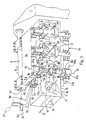
- Fig. 1 ist eine vereinfachte Perspektivdarstellung des für den vorliegenden Zusammenhang relevanten Teils einer vierstufigen Umformmaschine ;
- Fig. 2 veranschaulicht schematisch den Bewegungsablauf des verwendeten Führungsgetriebes ;
- Fig. 3 zeigt verschiedene Phasen der Drehbewegung des Rohlings ;
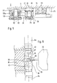
- Fig. 4 ist ein Vertikalschnitt längs einer in der Zangenachse liegenden Ebene ;
- Fig. 5 ist ein Vertikalschnitt längs der Linie V-V in Fig. 4, und
- Fig. 6 veranschaulicht die Ausführung der Zangenbacken für den kleinsten und den grössten Rohling.
- 1 is a simplified perspective illustration of the part of a four-stage forming machine relevant to the present context;
- Fig. 2 illustrates schematically the sequence of movements of the guide gear used;
- Fig. 3 shows different phases of the rotational movement of the blank;
- 4 is a vertical section along a plane lying in the axis of the pliers;
- Fig. 5 is a vertical section along the line VV in Fig. 4, and
- Fig. 6 illustrates the design of the jaws for the smallest and the largest blank.
Gemäss Fig. 1 ist auf einem Pressenrahmen 1 ein unterer Matrizenhalter 2 mit vier Ausnehmungen zur Aufnahme von Matrizen befestigt. Darüber sind vier Matrizenhalterdeckel 3, 4, 5 und 6 angebracht. Ober- und unterhalb dieser Matrizenhalterungen befinden sich Zangenträgerkasten (Führungsteile) 7a, 7b. Diese Zangenträgerkasten sind mittels Klemmverbund je auf einer Welle (Hauptwelle) 8 befestigt und haben die Aufgabe, die noch zu beschreibenden Zangenapparate mit den Wellen 8, von denen nur die obere sichtbar ist, zu verbinden. Jede dieser Wellen 8 ist im Pressenrahmen 1 dreh- und längsverschiebbar gelagert und beide sind genau gleichlaufend in Pfeilrichtung A bzw. gegenlaufend in Pfeilrichtung B, wobei A eine translatorische Bewegung in Richtung der Wellenachse 93 und B eine Winkelbewegung um die gleiche Achse darstellen. Ein nicht gezeigter Antriebsmechanismus übermittelt diesen Wellen die Bewegung, die zum Transportieren der Presslinge von einer Umformstation zur nächsten und zum Leerrücklauf notwendig ist.1, a
Dieser Bewegungsablauf erfolgt in zwei Teilen : Einerseits als Quertransportbewegung der Presslinge von einer Matrize vor die andere (Pfeil A), andererseits zum Öffnen und Schliessen der Zangen, bzw. zum Ergreifen oder Loslassen der Presslinge (Schwenkbewegung um die Welle 8, Pfeil B).This sequence of movements takes place in two parts: on the one hand as a transverse transport movement of the compacts from one die to the other (arrow A), on the other hand for opening and closing the pliers, or for gripping or releasing the compacts (swiveling movement around shaft 8, arrow B).
An der Frontseite der Zangenträgerkasten 7a, 7b sind drei Zangenpaare 9, 10, 11 lösbar befestigt. Während nun die Zangenpaare 10 und 11 der bekannten Form entsprechen und mit festen unteren Greifern 12 und federnd abgestützten oberen Greifern 13 versehen sind, wurde das erste Zangenpaar durch je eine drehbare Einrichtung (Zangenträger) 9a bzw. 9b ausgetauscht.Three pairs of
Der Draht oder die Stange wird in der Achse 14 in Pfeilrichtung gegen einen verstellbaren, nicht gezeigten Anschlag, womit die Abschnittlänge eingestellt wird, eingezogen und mit,dem schematisch dargestellten Schermesser 15 abgeschert.The wire or rod is retracted in the
Durch eine nicht gezeigte Vorrichtung am Schermesser 15 wird der abgescherte Abschnitt festgehalten und vor die erste Station gebracht. Dies ist beim vorstehenden Ausführungsbeispiel nicht die erste Unformstation, sondern eine reine Haltestation, in welcher der Abschnitt bis zur Übernahme durch die Zangen 9a/9b gehalten wird. Ein aus dem ersten Stempelwerkzeug des heranfahrenden Pressschlittens hervorstehender und federnd abgestützter Haltestift 16 drückt den abgescherten Rohling 17 aus der Haltevorrichtung am Schermesser gegen einen Anschlagbolzen 18, der anstelle einer 1. Matrize in die dafür vorgesehene Öffnung eingebaut wurde. Der Haltestift 16 hält den Rohling so lange, bis das insgesamt mit 9 bezeichnete Zangenpaar (Zangenträger), das sich mit den Quertransportträgern in die linke Endlage begeben hat, diesen durch die Schwenkbewegungen B ergriffen hat, während der nicht sichtbare, vor der Zeichenebene zu denkende Pressschlitten in seine hintere Lage zurückgeht, und damit auch den Haltestift 16 mit zurückzieht. Die Quertransportträger werden nun in ihre rechte Endlage bewegt. Während dieser Bewegung dreht sich ein oberer und ein unterer, in den Lagerhalterungen 22a und 22b drehbarer Greifer 19 bzw. 20, um 90° um die vertikale Achse 21. Diese Drehbewegung erhalten die Greifer durch je ein räumliches, d. h. dreidimensional bewegliches Zweischlaggetriebe 23a und 23b, das die Funktion eines Führungsgetriebes hat und dessen Aufgabe darin besteht, die den Rohling 17 haltenden Zangen 9 während ihrer Translationsbewegung zwangsläufig so zu führen, dass sich einerseits eine Drehung des Rohlings um 90° gegenüber der vertikalen Achse 21 ergibt und andererseits diese Drehung auf die translatorische Bewegung so abgestimmt ist, dass ein Grossteil der Winkelbewegung bereits in der ersten Hälfte des translatorischen Zangenweges erfolgt. Damit soll erreicht werden, dass das erforderliche Führungsgetriebe für seine Bewegung den kleinstmöglichen Raum beansprucht und insbesondere an den angrenzenden Matrizengehäusen keine, bzw. nur unwesentliche, konstruktive Änderungen, wie z. B. Aussparungen, vorgenommen werden müssen.The sheared section is held in place by a device (not shown) on the
Jedes der räumlichen Zweischlaggetriebe setzt sich zusammen aus einem Lenker 24 und einer Koppel 25. Der Lenker 24 weist an seinem hinteren Ende eine Lagerbüchse auf, die auf einem ortsfesten Zapfen, nach Fig. 5 um die Achse 28, drehbar gelagert ist. Die Verbindung zwischen Lenker 24 und Koppel 25 bildet ein Kugelgelenk 30, während die Koppel 25 an ihrem anderen Ende einen Drehzapfen aufweist, der in den um die Achse 21 schwenkbaren Teil (Übertragungsglied) 9c (oben) bzw. 9d (unten) der Einrichtung 9 eingreift und dort drehbar um die Achse 29a (oben) bzw. 29b (unten) gelagert ist.Each of the spatial two-stroke gearbox is composed of a
Fig. 2 zeigt schematisch die Darstellung des Bewegungsablaufes des räumlichen Zweischlaggetriebes, auf eine Horizontalebene projiziert. Die ausgezogenen Linien zeigen die Stellung des Führungsgetriebes, wenn sich der Quertransport in der rechten Endlage befindet, der Pressling 17 sich also um 90° gedreht vor der Umformstation befindet, während gestrichelt die linke Endlage dargestellt ist, der Pressling sich also noch in der Lage befindet, wie er vom Schermesser in die Ladestation gebracht wurde.Fig. 2 shows schematically the representation of the sequence of movements of the spatial two-stroke gear, projected onto a horizontal plane. The solid lines show the position of the guide gear when the transverse transport is in the right end position, i.e. the compact 17 is rotated by 90 ° in front of the forming station, while the left end position is shown in broken lines, so the compact is still in position how it was brought into the charging station by the clipper.
Der Lenker 24 ist also an seinem einen Ende auf einem ortsfesten Lager drehbar um die vertikale Achse 28 aufgesteckt. Dadurch wird dem anderen Ende, das durch das Kugelgelenk 30 mit der Koppel 25 verbunden ist, ermöglicht, sich auf einem Kreisbogen 31, in der Fig. 2 strichzweipunktiert, zu bewegen. Die Koppel 25 ist an ihrem greiferseitigen, dem Kugelgelenk 30 gegenüberliegenden Ende mit einem Drehzapfen versehen, der in den um die vertikale Achse 21 drehbaren Teil 9c bzw. 9d der Einrichtung 9 eingreift und um die Achse 29a/29b drehbar ist.The
Bewegt sich nun der durch die Welle 8 geradlinig geführte Zangenträger von der linken Endlage (das Zweischlaggetriebe 23 befindet sich also in der gestrichelt dargestellten Lage) in die rechte (in Fig. 2 ausgezogene) Endlage, so bewegt sich die Zangendrehachse von 21' entlang der Linie 32 nach 21, und der Kugelgelenkpunkt folgt dem Kreisbogen 31 von 30' nach 30. Durch die gewählte Geometrie wird die Koppel 25, welche einerseits auf dem Bogen 31 und andererseits auf der Geraden 32 geführt ist, um 90° gedreht, zumindest solange sich das Getriebe (wie in Fig. 2 dargestellt) in der Projektionsebene bewegt, dargestellt durch die Strecke 25a' bzw. 25a. Da nun der die Achse 29 bildende, in der Koppel 25 befestigte Drehzapfen in die um die senkrechte Achse 21 drehbare Einrichtung 9 eingreift, wird diese somit ebenfalls um 90° gedreht.If the pliers carrier, which is guided in a straight line by the shaft 8, now moves from the left end position (the two-
Fig. 6 zeigt die Übernahme des gedrehten Rohlings 33 durch den im 2. Stempel 34 des Pressschlittens eingebauten Federstift 35 und die Matrize 36. Durch das Vorfahren des Pressschlittens 34 wird der Rohling 33 durch den oder die Federstifte 35 aus den Zangenbacken 37, 38 gedrückt, bis der Rohling auf der Gravur 39 der Matrize anliegt. Die Form der Zangenbacken 37, 38 ist so ausgeführt, dass der Rohling auf der Matrizenseite ausgestossen werden kann, jedoch so lange geführt ist, bis er an die Gravur 39 der Matrize 36 angepresst wird, während er auf der anderen Seite an einer Schulter 40 anliegt. Nachdem nun der Rohling 33 mit dem Federstift 35 gehalten wird, schwenken der obere und untere Zangenträgerkasten um die Welle 8 um ein bestimmtes Mass auf (Pfeil B, Fig. 1), die Zangenbacken lassen also den Rohling los, d. h. die Zangen öffnen und machen damit dem heranfahrenden Stempel 34 Platz. Wegen des Hochschwenkens der Zangenträgerkasten beim Zurückfahren in die Ausgangsstellung ist es notwendig, das Gelenk 30 als Kugelgelenk und die Koppel 25 an ihrem Ankoppelungspunkt mit der drehbaren Einrichtung 9c/9d, an welcher sich die Zangenbacken 37 bzw. 38 befinden, um die Achse 29 drehbar auszuführen. Dadurch wird das Zurückdrehen der Einrichtung 9 in die Ausgangsstellung auch bei geöffneten Zangen gewährleistet. Durch das beschriebene Aufschwenken, welches das Zangenöffnen bewirkt, wird die drehbare Einrichtung 9 um einen kleinen, keinen Einfluss ausübenden Winkel gedreht, welcher beim Zurückschwenken, d. h. dem Zangenschliessen, wieder genau kompensiert wird.6 shows the takeover of the rotated blank 33 by the
Fig. 6 zeigt die Zangenbackenausführung für den grössten (strichpunktiert) und den kleinsten Rohling. Die Flächen zwischen den Auflagen 41 (Fig.4) sind schräg, um ein Ansammeln von Schmutz zu vermeiden.Fig. 6 shows the jaw design for the largest (dash-dotted) and the smallest blank. The areas between the pads 41 (Fig. 4) are slanted to prevent dirt from accumulating.
Fig. 4 zeigt einen zentralen Vertikalschnitt durch das Zangenpaar 9. Eine Lagerhalterung 43 ist mittels Schrauben 44 auf dem Zangenträgerkasten 7b aufgeschraubt. In der Lagerhalterung 43 befinden sich zwei Gleitlagerbüchsen 45. in denen das Drehteil (Übertragungsglied) 46 der Zangeneinheit gelagert ist. Die axiale Lage ergibt sich durch eine Schulter 47 und einen auf das untere Ende des Drehteils 46 aufgeschraubten Deckel 48. Oberhalb der Lagerung des Drehteils 46 weist dieses eine Öffnung für eine Lagerbüchse 49 auf, in die ein Zapfen 50 drehbar eingreift, welcher fest mit der Koppel 25 verbunden ist. Die Koppel 25 könnte den Zapfen 50 von beiden Stirnseiten her gabelförmig umgreifen. Um das Verschmutzungsrisiko auszuschliessen, greift die Koppel 25, wie sich u. a. aus Fig. 1 ergibt, nur von einer Seite am Zapfen 50 an, an welchem sie durch bekannte Mittel befestigt ist. Ebenfalls fest mir der Koppel 25 verbunden ist ein Gehäuse 51, welches nach hinten einen Schlitz s (Fig. 5) aufweist, und welches als Halterung für den Kugelgelenkzapfen 52 dient. Den Kugelgelenkzapfen 52 umschliesst eine Kugel 53. Der Lenker ist mit einer Kugelkalotte 53a versehen, die die Kugel 53 umschliesst und gegenüber dieser in bekannter Weise verdrehbar ist.4 shows a central vertical section through the pair of
Am oberen Teil des Drehteils 46 sind zwei parallele Flächen 54 angefräst ; als Gegenstück dazu weist der Zangenbackenträger 55 einen Schlitz 56 auf, so dass der Zangenbackenträger 55 die beiden Flächen 54 übergreift. Dadurch ist die richtige Lage des Zangenbackenträgers 55 gegenüber dem Drehteil 46 gewährleistet und die beiden Teile sind gegen eine Relatiwerdrehung gesichert. Als Verbindung zwischen dem Drehteil 46 und dem Zangenbackenträger 55 dient eine Klemmhülse 57, mittels welcher das Drehteil 46 und der Zangenbackenträger 55 fest, d. h. drehstarr verbunden werden. Zur genauen Höhenverstellung des Zangenbackenträgers dient eine Stellschraube 58, die in eine mit der Klemmhülse 57 fest verbundene Öse 59 geschraubt ist, und die nach dem Lösen einer Sicherungsmutter 60 und einer Klemmschraube 61 gedreht werden kann und dadurch die Höhe des Anschlages 62, der am Zangenbackenträger 55 angeformt ist, verstellt. Die Zangenbacke 63, die zum Halten des Rohlings 64 dient, ist mit einer Schraube 65 auf dem Zangenbackenträger angeschraubt, und entsprechende Führungsflächen gewährleisten die richtige Lage.At the upper part of the
Die obere Zangenhälfte ist im Prinzip gleich aufgebaut wie die untere, weist aber den Unterschied auf, dass sie in axialer, d. h. vertikaler Richtung federnd gelagert ist. Deshalb ist der obere Zangenbackenträger 66 mit einer Hülse 67, die nur mit dem Drehteil 68 mit Klemmverbund gekoppelt ist, längsverschiebbar in einer Büchse 69 gelagert. Eine Feder 70, die in einer Zentralbohrung des Zangenbackenträgers geführt ist, drückt diesen und damit die Zangenbacke 71 auf den Rohling 64. Der Federweg X wird mit einer Schraube 72 nach Lösen einer Sicherungsmutter 73 durch Verdrehen eingestellt. Um zu verhindern, dass beim Ausbau des Zangenbackenträgers 66 die Feder herausschnellt, ist am oberen Ende des Zangenbackenträgers 66 ein Querstift 96 eingebaut. Die Befestigung am oberen Zangenbackenträger ist gleich wie unten, ebenso der Drehantrieb.The upper half of the pliers is constructed in principle the same as the lower, but has the difference that it is in the axial, ie. H. is supported in the vertical direction. Therefore, the
Damit zwischen Matrizenhalter 2 und unterem Zangenkastenträger 7b für den Drehantrieb 23a/23b Platz vorhanden ist, muss der Matrizenhalter 2 im Bereich der 1. Matrize mit einer Ausnehmung 74 (Fig. 1 und 4) versehen sein.So that there is space between the
Fig. 5 zeigt anhand eines Vertikalschnittes das Festlager des unteren räumlichen Zweischlag-Drehantriebes. Eine Konsole 75 ist unten am Matrizenhalter 2 festgeschraubt. Mit dieser Konsole 75, die als Montagehilfe dient, ist eine Halteplatte 76 lösbar verbunden. Mit dieser Halteplatte 76 ist ein Lagerzapfen 77 starr verbunden. Über den Lagerzapfen 77 ist der mit einer Lagerbüchse 78 versehene Lenker 24 gelegt, und mit an den Lagerzapfen 77 angeschraubtem Deckel 79 gesichert. Um das Eindringen von Schmutz zu verhindern, ist die Lagerbüchse 78 oben mit einer Dichtung 80 versehen, während die Lagerung unten mit einem Deckel 81 abgeschlossen ist. Diese Lagerung erlaubt dem Lenker 24 die Drehung um die Achse 28 (Fig. 2). Am andern Ende des Lenkers 24 ist das Kugelgelenk ersichtlich, welches bereits unter Fig. 4 beschrieben wurde. Ersichtlich ist hier, wie der Kugelgelenkzapfen 52 mit einem konischen Stift 82 am Gehäuse 51, welches mit der Koppel 25 fest verbunden ist, festgemacht wird.5 shows, using a vertical section, the fixed bearing of the lower spatial two-stroke rotary drive. A
Das obere Festlager ist auf einen Haltebügel 26 (Fig. 1) montiert. Dieser wird durch einen hydraulisch betätigten Zylinder 27, der zugleich zum Hochschwenken des oberen Zangenträgerkastens 7a dient, auf den Matrizenhalterdeckel 3 gedrückt und somit ortsfest gehalten.The upper fixed bearing is mounted on a bracket 26 (Fig. 1). This is pressed onto the
Bei dieser Vorrichtung ist es eine Bedingung, dass, wenn der Rohling in die 1. Station bis auf den Anschlag 18 (Fig. 1) eingestossen wurde, sich sein Mittelpunkt oder Schwerpunkt in der Drehachse 21 des Zangenpaares 9 befindet. Dies bedeutet, dass wenn die Abschnittlänge beim Abschervorgang geändert wird, sich auch die Eindringtiefe in die 1. Station ändern muss, d. h. der Anschlag 18 muss verstellt werden. Wenn der Abschnitt um das Mass a verkürzt wird, muss der Anschlag um das Mass a/2 nach vorne gestellt werden. Gemäss vorliegendem Beispiel wird der Anschlag 18 mit der Abschnittlängenverstellung mechanisch oder elektrisch gekoppelt, damit die Stellung des Anschlags 18 immer der Abschnittlänge entspricht und der Schwerpunkt des Rohlings immer den gleichen Abstand von der Matrizenvorderseite aufweist, wie die Drehachse 21 der Dreheinrichtung 9.In this device, it is a condition that when the blank has been pushed into the 1st station up to the stop 18 (FIG. 1), its center or center of gravity is located in the axis of
Fig. 3 zeigt den Bewegungsablauf des sich drehenden Rohlings. Wenn sich die Quertransportvorrichtung in der Ausgangslage befindet, liegt der Rohling 83 am Anschlagbolzen 18 an, welcher in einem, anstelle der normalen Umformmatrize in der dafür vorgesehenen Öffnung eingesetzten, Füllstück 84 eingebaut ist. Bei Beginn der Quertransportbewegung wird auch sofort mit dem Drehen des Rohlings begonnen. Das Füllstück 84 ist gegenüber der normalen Matrizenvorderkante zurückversetzt, um für den langen Rohling Platz zu lassen. Aus der Figur ist ersichtlich, dass der sich drehende Rohling 85 mit dem Matrizenhalter 2 kollidieren würde. Deshalb ist dort eine Ausnehmung 86 angeordnet. Auch die in die 2. Station eingelegte Matrize 87 weist noch eine kleine Anpassung 88 auf. Diese Anpassung 88 kann deshalb so gering gehalten werden, weil der Rohling, wegen der Wahl des räumlichen Zweischlages als Drehantrieb und wegen der geometrischen Anordnung der Gelenke, vor dem Durchlaufen des halben translatorischen Hubes bereits um wesentlich mehr als 45°, bei vorliegendem Beispiel um etwa 60°, gedreht ist. Dadurch erfährt die Matrize 87 praktisch keine Einschränkung und ist somit eine vollwertige Umformmatrize.Fig. 3 shows the sequence of movements of the rotating blank. When the transverse transport device is in the starting position, the blank 83 lies against the
Um bei Arbeiten am Werkzeugraum eine gute Zugänglichkeit zu erhalten, kann der obere Zangenträgerkasten 7a um die Welle 8 hochgeschwenkt werden (Fig. 1). Dazu wird die Welle 8 vom nicht gezeigten Antriebsmechanismus abgekuppelt und über die linke Ausgangsstellung (1. Zange vor 1. Matrize) hinausgeschoben, bis das vorstehende Profilstück 90, welches als Fortsetzung der Welle 92, auf welcher der Lagerhaltebügel 26 angebracht ist, und welche in der gleichen Achse 93 gelagert ist wie Welle 8, in die passende Öffnung 91 hineinragt. Dann kann mit dem Zylinder 27 der obere Zangenträgerkasten 7a hochgeschwenkt werden. Der Lagerhaltebügel 26 dreht sich mit, inklusive Drehantrieb 23. Somit kann der obere Zangenträgerkasten 7a ohne Probleme hochgeschwenkt werden.In order to obtain good accessibility when working on the tool space, the upper
Für die Umrüstung auf normale Umformung, d. h. ohne Drehen des Rohlings, kann die drehbare Einrichtung 9 durch ein ursprüngliches Zangenpaar (Ausführung 10, 11, Fig. 1) ersetzt werden. Der Drehantrieb 23 bleibt an den Zangeneinheiten, d. h. der obere wird vom Lagerhaltebügel 26 durch Lösen der Schrauben 95 getrennt, während der untere Drehantrieb durch Lösen der Schrauben 95 (Fig. 5) von der Führungseinrichtung getrennt wird. Ein schnelles Umrüsten zur Umformung von herkömmlichen Teilen ist dadurch gewährleistet.For the conversion to normal forming, d. H. without rotating the blank, the
Bei vorstehend beschriebenem Ausführungsbeispiel wurde zwischen der Abscherstation und der ersten Umformstation II eine Vorhaltestation I eingeschaltet, deren Hauptfunktion darin besteht, den abgescherten Abschnitt so lange zu halten, bis er von den Zangen 19 und 20 sicher ergriffen wurde. Es wäre aber durchaus möglich, bereits in der Station I eine Umformung durchzuführen. Auch könnte die beschriebene Wendevorrichtung ganz allgemein zwischen zwei beliebigen Nachbarstationen, z. B. zwischen den Umformstationen 111 und IV, angebracht werden.In the exemplary embodiment described above, a holding station I was switched on between the shearing station and the first forming station II, the main function of which is to hold the sheared section until it has been gripped securely by the
Das Ausführungsbeispiel zeigt eine mehrstufige Umformmaschine mit horizontaler Pressstempelbewegung. Das beanspruchte Prinzip lässt sich aber gleichermassen auch auf vertikal arbeitenden Maschinen anwenden.The exemplary embodiment shows a multi-stage forming machine with horizontal press ram movement. The principle claimed can also be applied equally to vertical machines.
Gemäss einer bevorzugten Ausführungsform der Erfindung sind beide Zangen 19 und 20 (Fig. 1) mit einem Führungsgetriebe 23 gekoppelt. Es wäre aber auch möglich, nur eine Zange zwangsläufig über ein solches Führungsgetriebe zu führen und die andere lose drehbar anzuordnen.According to a preferred embodiment of the invention, both
Claims (8)
Priority Applications (1)
| Application Number | Priority Date | Filing Date | Title |
|---|---|---|---|
| AT81104252T ATE6834T1 (en) | 1980-06-10 | 1981-06-03 | MULTI-STAGE FORMING MACHINE. |
Applications Claiming Priority (2)
| Application Number | Priority Date | Filing Date | Title |
|---|---|---|---|
| DE3021695 | 1980-06-10 | ||
| DE3021695 | 1980-06-10 |
Publications (4)
| Publication Number | Publication Date |
|---|---|
| EP0041690A2 EP0041690A2 (en) | 1981-12-16 |
| EP0041690A3 EP0041690A3 (en) | 1982-03-17 |
| EP0041690B1 EP0041690B1 (en) | 1984-03-28 |
| EP0041690B2 true EP0041690B2 (en) | 1988-11-30 |
Family
ID=6104229
Family Applications (1)
| Application Number | Title | Priority Date | Filing Date |
|---|---|---|---|
| EP81104252A Expired EP0041690B2 (en) | 1980-06-10 | 1981-06-03 | Multistage metal-forming machine |
Country Status (5)
| Country | Link |
|---|---|
| US (1) | US4430882A (en) |
| EP (1) | EP0041690B2 (en) |
| JP (1) | JPS6018266B2 (en) |
| AT (1) | ATE6834T1 (en) |
| DE (1) | DE3162864D1 (en) |
Families Citing this family (10)
| Publication number | Priority date | Publication date | Assignee | Title |
|---|---|---|---|---|
| JP2652850B2 (en) * | 1985-10-11 | 1997-09-10 | オ−ビタル、エンジン、カンパニ−、プロプライエタリ、リミテッド | Fuel metering method and apparatus |
| EP0559991B1 (en) * | 1992-02-11 | 1995-05-03 | Hatebur Umformmaschinen AG | Turning device for cross-transfer presses |
| US5498895A (en) * | 1993-07-07 | 1996-03-12 | Actel Corporation | Process ESD protection devices for use with antifuses |
| JPH0984982A (en) * | 1995-09-20 | 1997-03-31 | Kanto Sheet Seisakusho:Kk | Thread breakage detector for sewing machine |
| DE19545570A1 (en) * | 1995-12-07 | 1997-06-12 | Schuler Pressen Gmbh & Co | Transfer device for multi-station presses |
| WO2003080875A2 (en) * | 2002-03-26 | 2003-10-02 | Nedschroef Herentals N.V. | Device for transferring wire pieces |
| KR101712957B1 (en) * | 2016-05-26 | 2017-03-22 | 대한메탈(주) | Cold forging former apparatus with function of direction changing of shapes |
| US10857585B2 (en) * | 2016-05-26 | 2020-12-08 | Daido Steel Co., Ltd. | Transfer device of multistage forging press machine |
| JP6096360B1 (en) * | 2016-08-12 | 2017-03-15 | 旭サナック株式会社 | Work posture changing device and multi-process forging machine |
| KR102351104B1 (en) * | 2017-11-29 | 2022-01-14 | 한국과학기술원 | Power generation system using proton boron nuclear reaction |
Family Cites Families (11)
| Publication number | Priority date | Publication date | Assignee | Title |
|---|---|---|---|---|
| FR1210969A (en) * | 1957-09-25 | 1960-03-11 | Waterbury Farrel Foundry Co | Transfer mechanism for head forming machines and similar machines |
| US3165766A (en) * | 1961-08-29 | 1965-01-19 | Nat Machinery Co | Transfer for metal forming machine |
| DE1189359B (en) * | 1963-02-26 | 1965-03-18 | Nedschroef Octrooi Maats | Transport device on a multiple printing press |
| US3217343A (en) * | 1963-05-06 | 1965-11-16 | Lamson & Sessions Co | Transfer mechanism with rotatable work engaging means |
| US3466917A (en) * | 1966-10-19 | 1969-09-16 | Nat Machinery Co The | Method and apparatus for forging blanks |
| DE2318449C2 (en) * | 1973-04-12 | 1982-09-09 | L. Schuler GmbH, 7320 Göppingen | Infeed and discharge device for sheet or band-shaped workpieces on presses |
| US3965718A (en) * | 1973-07-23 | 1976-06-29 | The National Machinery Company | Transfer mechanism |
| BE827766R (en) * | 1974-11-18 | 1975-07-31 | TRANSFER MECHANISM | |
| DE2715966C3 (en) * | 1977-04-09 | 1980-03-27 | Hatebur Umformmaschinen Ag, Basel (Schweiz) | Device for the automatic transport of workpieces on multi-stage cross transport presses |
| DE2800828A1 (en) * | 1978-01-10 | 1979-07-12 | Krupp Gmbh | DEVICE FOR TURNING WORKPIECES |
| US4351180A (en) * | 1980-06-30 | 1982-09-28 | The National Machinery Company | Workpiece turning transfer |
-
1981
- 1981-05-29 US US06/268,206 patent/US4430882A/en not_active Expired - Fee Related
- 1981-05-30 JP JP56083689A patent/JPS6018266B2/en not_active Expired
- 1981-06-03 AT AT81104252T patent/ATE6834T1/en not_active IP Right Cessation
- 1981-06-03 EP EP81104252A patent/EP0041690B2/en not_active Expired
- 1981-06-03 DE DE8181104252T patent/DE3162864D1/en not_active Expired
Also Published As
| Publication number | Publication date |
|---|---|
| JPS6018266B2 (en) | 1985-05-09 |
| ATE6834T1 (en) | 1984-04-15 |
| EP0041690B1 (en) | 1984-03-28 |
| EP0041690A3 (en) | 1982-03-17 |
| DE3162864D1 (en) | 1984-05-03 |
| US4430882A (en) | 1984-02-14 |
| EP0041690A2 (en) | 1981-12-16 |
| JPS5725238A (en) | 1982-02-10 |
Similar Documents
| Publication | Publication Date | Title |
|---|---|---|
| DE602005005575T2 (en) | Bending form with a vice for clamping an elongate element in a bending machine | |
| DE3434009C2 (en) | ||
| DE4330683C2 (en) | Folding device | |
| DE3120772A1 (en) | WELDING DEVICE FOR A MOTOR VEHICLE BODY | |
| DE19621658C2 (en) | Processing machine for plate-shaped workpieces, in particular for producing curved edges on sheet metal parts | |
| DE2708457C2 (en) | Transport mechanism for forging machines | |
| DE2359918C3 (en) | Device for feeding and removing workpieces made of flat material | |
| DE2930006A1 (en) | Machine-tool mechanical loading grab - has spring components held rigid during transport and allowing movement during transfer | |
| EP0041690B2 (en) | Multistage metal-forming machine | |
| DE69832426T2 (en) | Pressing device for sheet metal | |
| DE202020003482U1 (en) | Universal welding bench | |
| DE3832244C2 (en) | Bending machine | |
| DE3831210A1 (en) | Pivoting device for a stop plate for positioning workpieces (stock stop) | |
| DE4217809A1 (en) | DEVICE FOR TOOL MAGAZINES OF SHEET MACHINING MACHINES | |
| DE3136169A1 (en) | DEVICE FOR INSERTING A WORKPIECE IN THE TOOL SPACE OF A DIE FORGING PRESS AND THE LIKE | |
| DE3503637A1 (en) | Machine tool for the cutting machining of workpieces with different tools | |
| DE2920059A1 (en) | Bender and crimper for connecting wires of electrical components - has storage section for components and wire shearing tool and has synchroniser for reciprocating movements | |
| DE3137811A1 (en) | CLAMPING DEVICE | |
| EP1056556A1 (en) | Flanging device with pressing and clamping elements | |
| CH655887A5 (en) | CONVERSION DEVICE ON FORMING MACHINE. | |
| EP0252167B1 (en) | Machine for the attachment to garments of buttons, rivets or the like | |
| EP0021166A1 (en) | Forging device | |
| DE8015357U1 (en) | MULTI-STAGE FORMING MACHINE | |
| DE102016215450A1 (en) | Add pliers | |
| DE2106478A1 (en) | Device for reducing or eliminating vibrations of a rod-shaped material when rotating in a feed mechanism |
Legal Events
| Date | Code | Title | Description |
|---|---|---|---|
| PUAI | Public reference made under article 153(3) epc to a published international application that has entered the european phase |
Free format text: ORIGINAL CODE: 0009012 |
|
| AK | Designated contracting states |
Designated state(s): AT BE CH DE FR GB IT NL SE |
|
| ITCL | It: translation for ep claims filed |
Representative=s name: BARZANO' E ZANARDO MILANO S.P.A. |
|
| PUAL | Search report despatched |
Free format text: ORIGINAL CODE: 0009013 |
|
| TCNL | Nl: translation of patent claims filed | ||
| AK | Designated contracting states |
Designated state(s): AT BE CH DE FR GB IT NL SE |
|
| 17P | Request for examination filed |
Effective date: 19820625 |
|
| ITF | It: translation for a ep patent filed |
Owner name: BARZANO' E ZANARDO MILANO S.P.A. |
|
| GRAA | (expected) grant |
Free format text: ORIGINAL CODE: 0009210 |
|
| AK | Designated contracting states |
Designated state(s): AT BE CH DE FR GB IT LI NL SE |
|
| REF | Corresponds to: |
Ref document number: 6834 Country of ref document: AT Date of ref document: 19840415 Kind code of ref document: T |
|
| REF | Corresponds to: |
Ref document number: 3162864 Country of ref document: DE Date of ref document: 19840503 |
|
| ET | Fr: translation filed | ||
| PLBI | Opposition filed |
Free format text: ORIGINAL CODE: 0009260 |
|
| 26 | Opposition filed |
Opponent name: L. SCHULER GMBH Effective date: 19841218 |
|
| NLR1 | Nl: opposition has been filed with the epo |
Opponent name: L. SCHULER GMBH |
|
| ITF | It: translation for a ep patent filed |
Owner name: BARZANO' E ZANARDO MILANO S.P.A. |
|
| PUAH | Patent maintained in amended form |
Free format text: ORIGINAL CODE: 0009272 |
|
| STAA | Information on the status of an ep patent application or granted ep patent |
Free format text: STATUS: PATENT MAINTAINED AS AMENDED |
|
| 27A | Patent maintained in amended form |
Effective date: 19881130 |
|
| AK | Designated contracting states |
Kind code of ref document: B2 Designated state(s): AT BE CH DE FR GB IT NL SE |
|
| NLR2 | Nl: decision of opposition | ||
| NLR3 | Nl: receipt of modified translations in the netherlands language after an opposition procedure | ||
| ET3 | Fr: translation filed ** decision concerning opposition | ||
| ITTA | It: last paid annual fee | ||
| PGFP | Annual fee paid to national office [announced via postgrant information from national office to epo] |
Ref country code: GB Payment date: 19940526 Year of fee payment: 14 |
|
| PGFP | Annual fee paid to national office [announced via postgrant information from national office to epo] |
Ref country code: SE Payment date: 19940527 Year of fee payment: 14 |
|
| PGFP | Annual fee paid to national office [announced via postgrant information from national office to epo] |
Ref country code: AT Payment date: 19940601 Year of fee payment: 14 |
|
| PGFP | Annual fee paid to national office [announced via postgrant information from national office to epo] |
Ref country code: FR Payment date: 19940629 Year of fee payment: 14 |
|
| PGFP | Annual fee paid to national office [announced via postgrant information from national office to epo] |
Ref country code: NL Payment date: 19940630 Year of fee payment: 14 |
|
| PGFP | Annual fee paid to national office [announced via postgrant information from national office to epo] |
Ref country code: BE Payment date: 19940705 Year of fee payment: 14 |
|
| PGFP | Annual fee paid to national office [announced via postgrant information from national office to epo] |
Ref country code: DE Payment date: 19940830 Year of fee payment: 14 |
|
| EAL | Se: european patent in force in sweden |
Ref document number: 81104252.2 |
|
| PG25 | Lapsed in a contracting state [announced via postgrant information from national office to epo] |
Ref country code: GB Effective date: 19950603 Ref country code: AT Effective date: 19950603 |
|
| PG25 | Lapsed in a contracting state [announced via postgrant information from national office to epo] |
Ref country code: SE Effective date: 19950604 |
|
| PGFP | Annual fee paid to national office [announced via postgrant information from national office to epo] |
Ref country code: CH Payment date: 19950627 Year of fee payment: 15 |
|
| PG25 | Lapsed in a contracting state [announced via postgrant information from national office to epo] |
Ref country code: BE Effective date: 19950630 |
|
| BERE | Be: lapsed |
Owner name: HATEBUR UMFORMMASCHINEN A.G. Effective date: 19950630 |
|
| PG25 | Lapsed in a contracting state [announced via postgrant information from national office to epo] |
Ref country code: NL Effective date: 19960101 |
|
| GBPC | Gb: european patent ceased through non-payment of renewal fee |
Effective date: 19950603 |
|
| PG25 | Lapsed in a contracting state [announced via postgrant information from national office to epo] |
Ref country code: FR Effective date: 19960229 |
|
| NLV4 | Nl: lapsed or anulled due to non-payment of the annual fee |
Effective date: 19960101 |
|
| PG25 | Lapsed in a contracting state [announced via postgrant information from national office to epo] |
Ref country code: DE Effective date: 19960301 |
|
| EUG | Se: european patent has lapsed |
Ref document number: 81104252.2 |
|
| REG | Reference to a national code |
Ref country code: FR Ref legal event code: ST |
|
| PG25 | Lapsed in a contracting state [announced via postgrant information from national office to epo] |
Ref country code: LI Effective date: 19960630 Ref country code: CH Effective date: 19960630 |
|
| REG | Reference to a national code |
Ref country code: CH Ref legal event code: PL |