EP0040791B1 - Hauseinführung, für Medium-Transportleitungen insbesondere für Gas- und Wasserleitungen - Google Patents
Hauseinführung, für Medium-Transportleitungen insbesondere für Gas- und Wasserleitungen Download PDFInfo
- Publication number
- EP0040791B1 EP0040791B1 EP81103830A EP81103830A EP0040791B1 EP 0040791 B1 EP0040791 B1 EP 0040791B1 EP 81103830 A EP81103830 A EP 81103830A EP 81103830 A EP81103830 A EP 81103830A EP 0040791 B1 EP0040791 B1 EP 0040791B1
- Authority
- EP
- European Patent Office
- Prior art keywords
- house
- tube
- seal
- gas
- medium
- Prior art date
- Legal status (The legal status is an assumption and is not a legal conclusion. Google has not performed a legal analysis and makes no representation as to the accuracy of the status listed.)
- Expired
Links
Images

Classifications
-
- F—MECHANICAL ENGINEERING; LIGHTING; HEATING; WEAPONS; BLASTING
- F16—ENGINEERING ELEMENTS AND UNITS; GENERAL MEASURES FOR PRODUCING AND MAINTAINING EFFECTIVE FUNCTIONING OF MACHINES OR INSTALLATIONS; THERMAL INSULATION IN GENERAL
- F16L—PIPES; JOINTS OR FITTINGS FOR PIPES; SUPPORTS FOR PIPES, CABLES OR PROTECTIVE TUBING; MEANS FOR THERMAL INSULATION IN GENERAL
- F16L47/00—Connecting arrangements or other fittings specially adapted to be made of plastics or to be used with pipes made of plastics
- F16L47/005—Connecting arrangements or other fittings specially adapted to be made of plastics or to be used with pipes made of plastics the first pipe being joined to the ends of two other pipes placed one inside the other, e.g. gas pipe with protective sheath
Definitions
- the invention relates to a house entry for medium transport lines, in particular for gas and water lines, as characterized in the preamble of claim 1.
- plastic pipes are usually used outside the building and inside the same metal pipes.
- GB-A-15 57813 has disclosed a device with the features mentioned at the beginning.
- the supply pipe made of plastic and the refractory pipe are connected with a fitting, so that an indirect connection of both pipes by means of a screw connection is made with the house connection piece.
- a wall 1 of a building with an inner 2 and an outer surface 3 is shown. Through the wall 1 leads through 4, which is concreted in the wall 1.
- the house bushing 4 consists of a casing tube 5, for. B. made of steel or iron, or another non-combustible material that is expanded in the shape of a truncated cone at the outer end 6.
- the casing tube 5 is provided with welded, cast or molded bodies 7, 8, of which the 7 serve for radial and the other 8 for axially anchoring the casing tube 5 in the wall 1.
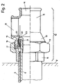
- a plastic tube 9 is arranged approximately coaxially in the interior of the jacket tube 5 and is connected to a medium supply source, for example a gas source, and is connected to the jacket tube 5 in a gas-tight and watertight manner adjacent to the inner surface 2 with a transition part 10, which is shown in FIG. 2 is shown on a larger scale.
- a medium supply source for example a gas source
- the transition part 10 mainly consists of a T-piece 11, the first opening 12 of which is gas-tight with the jacket tube 5 and the tube by means of a union nut 13 Plastic tube 9 is screwed.
- the T-piece 11 is provided on the second, axially opposite opening 14 with a screw closure, not shown, which can be unscrewed for cleaning the house entry 4 or the plastic pipe 9.
- the third. Opening 15 of the T-piece 11 serves to receive a pipe or valve for supplying the medium, preferably gas or water, to the interior of the building.
- the casing tube 5 When building the house wall 1 or later, the casing tube 5 is used and cemented. When the medium connection is to be established, the plastic tube 9 is displaced from the inside or outside through the jacket tube 5. Thereafter, an insert 16 pushed through the union nut 13 is screwed gas-tight onto the casing tube 5 and the union nut 13 is displaced as far as possible towards the inner surface 2. Then a spring washer seal 17, a wedge ring 18 and an annular seal 19 are moved over the exposed end of the plastic tube 9. A support nipple 20 is then hammered into the end 21 of the plastic tube 9.
- the support nipple is provided on the outside with ring-shaped barbs, which hold the support nipple 20 after driving in such a way that it can practically no longer be pulled out.
- the support nipple 20 thus holds the parts 17, 18 and 19 in such a way that they cannot be removed from the plastic tube 9.
- the T-piece 11 or its first opening 12 is moved over the parts 18 and 19 against the spring washer seal 17 and the union nut 13 is brought into engagement with the external thread of the T-piece 11 around the first opening 12 and tightened.
- the seal 17 presses the wedge ring 18 over the ring seal 19, so that a gas-tight connection is created.
- the annular surface 22 of the T-piece 11 presses against the annular surface 23 on the support nipple 20, so that a gas-tight connection is created.
- the parts 18-20 z. B. consist of plastic, but the spring washer seal 17 is made of metal or another refractory material, so that a completely metallic or otherwise fireproof shielding of the plastic tube 9 is guaranteed against fire.
- the casing tube 5 can, for. B. also consist of asbestos, concrete, brick, ceramic or Eternitt. Furthermore, the tube 5, for. B. in conversions, consist of an existing metal feed pipe that has been cut to the appropriate length. This z. B. masonry avoided. This solution is always possible if the existing, already walled-in pipe has a sufficient diameter.
- the house entry described is very easy to assemble, monitor and repair. If, for example, the plastic pipe has to be replaced for any reason, it is possible without replacing the casing pipe.
- connection work Since the transition from the plastic to the steel pipe is inside the building, the connection work is very easy and can be carried out under pleasant working conditions.
Landscapes
- Engineering & Computer Science (AREA)
- General Engineering & Computer Science (AREA)
- Mechanical Engineering (AREA)
- Pipeline Systems (AREA)
- Pipe Accessories (AREA)
- Rigid Pipes And Flexible Pipes (AREA)
Description
- Die Erfindung betrifft eine Hauseinführung für Medium-Transportleitungen, insbesondere für Gas-und Wasserleitungen, wie sie im Oberbegriff von Anspruch 1 gekennzeichnet ist.
- Wenn ein Gebäude an einem Versorgungsnetz für brennbare Medien, insbesondere an einem Gasleitungsnetz anzuschliessen ist, gilt die Forderung, dass im Gebäudeinneren, wegen der Feuergefahr, keine Kunststoffrohre verwendet werden dürfen, sofern sie nicht vollständig mit feuerfesten Ummantelungen, z. B. Metallrohren, umkapselt sind. Aus diesem Grunde werden heute in der Regel Kunststoffrohre ausserhalb des Gebäudes und im Inneren desselben Metallrohre verwendet.
- Durch die GB-A-15 57813 ist eine Vorrichtung mit den eingangs angeführten Merkmalen bekanntgeworden. Das Zufuhrrohr aus Kunststoff und das feuerfeste Rohr sind hierbei mit einem Formstück verbunden, so dass eine indirekte Verbindung beider Rohre mittels eines Schraubanschlusses mit dem Hausanschlussstück erfolgt.
- Nachteilig hierbei ist, dass für das Anziehen der beiden Dichtungen für eine gasdichte Abdichtung an den Rohrverbindungen zwei verschiedene Verschraubungen erforderlich sind, von denen die eine nur nach Demontage des Hausanschlussstückes zugänglich ist.
- Ferner ist es bei dieser Vorrichtung kaum möglich ohne Demontage des Hausanschlussstückes die Zufuhrleitung von flüssigen und festen Rückständen zu reinigen, die sich wegen Mediumsausscheidungen, beispielsweise im Gas oder im Wasser oder infolge von Rohrschäden, in der Hauseinführung ablagerten.
- Ausgehend vom vorgenannten Stand der Technik ist es Aufgabe der vorliegenden Erfindung, das bestehende Prinzip der Hauseinführungen wesentlich vereinfachen und zu verbessern, sowie deren Kontrolle zu erleichtern, damit eine sichere mediums-, beispielsweise gasdichte, einfache und dauerhafte Hauseinführung entsteht, die einfache und periodische Kontrollen mit geringstem Kostenaufwand ermöglicht.
- Diese Aufgabe ist erfindungsgemäss mit der Lehre gemäss dem gekennzeichneten Teil des Anspruches 1 gelöst.
- Ausführungsformen dieser Lehre sind in den weiteren, abhängigen Ansprüchen umschrieben.
- Die beschriebene Ausführung weist ü. a. die folgenden Vorteile auf :
- - eine Kontrolle der Hauseinführung auf Dichtigkeit ist im Hausinneren möglich, wobei auch beide Dichtungen ohne irgend eine Demontage im Hausinneren an einer Stelle gleichzeitig nachgezogen werden können,
- - eine dauerhafte Abdichtung ist dadurch gewährleistet, dass ein das Medium führendes Kunststoffrohr in einem Mantelrohr angeordnet ist, das über eine Schraubverbindung mit der Innenverrohrung verbunden ist, wobei diese Verschraubung auch das Kunststoffrohr mit der Verrohrung mediumsdicht verbindet,
- - eine Ueberdehnung des Kunststoffrohres, die ein Leck verursacht, kann nicht zum Eindringen von Medium, insbesondere Gas, in das Hausinnere führen, so dass Beschädigungen des Kunststoffrohres bei Erdarbeiten für die Hausbewohner deshalb ungefährlich sind, weil ausströmendes Medium, insbesondere Gas, durch des Mantelrohr in die Atmosphäre allenfalls ins Erdreich, ausserhalb des Hauses, strömt,
- - eine Reinigung zum Entfernen von Mediumsrückständen z. B. Ablagerungen von Gasfeststoffen oder Erde, infolge Rohrbruch, in der Hauseinführung, ist in einfacher Weise durch Oeffnen einer Reinigungsöffnung im Gebäudeinneren möglich, die axial mit dem Kunststoff- und dem Mantelrohr ausgerichtet ist.
- Nachfolgend wird ein Ausführungsbeispiel der erfindungsgemässen Hauseinführung anhand der Zeichnung näher erläutert.
- Es zeigen :
- Figur 1 eine Seitenansicht einer in einer Hauswand angeordneten Hauseinführung mit einem Ausschnitt von 90°, und
- Figur 2 einen Ausschnitt aus Fig. 1, der den im Hausinneren gelegenen Teil der Hauseinführung darstellt, in grösserem Massstab.
- In Fig. 1 ist eine Mauer 1 eines Gebäudes mit einer Innen- 2 und eine Aussenfläche 3 dargestellt. Durch die Mauer 1 führt eine Hausdurchführung 4, die in der Mauer 1 einbetoniert ist. Die Hausdurchführung 4 besteht aus einem Mantelrohr 5, z. B. aus Stahl oder Eisen, oder einem anderen, nicht brennbaren Werkstoff, das am äusseren Ende 6 kegelstumpfförmig ausgeweitet ist. Im mittleren Mauerbereich ist das Mantelrohr 5 mit angeschweissten, angegossenen oder angeformten Körpern 7, 8 versehen, von denen die einen 7 zur Radial- und die anderen 8 zur Axialverankerung des Mantelrohres 5 in der Mauer 1 dienen.
- Etwa koaxial im Inneren des Mantelrohres 5 ist ein Kunststoffrohr 9 angeordnet, das mit einer Mediumsversorgungsquelle, beispielsweise einer Gasquelle, verbunden ist und benachbart zur Innenfläche 2 zusammen mit dem Mantelrohr 5 gas- und wasserdicht mit einem Uebergangsteii 10 verbunden ist, der in Fig. 2 in grösserem Massstab dargestellt ist.
- Aus Fig. 2 geht hervor, dass der Uebergangsteil 10 zur Hauptsache aus einem T-Stück 11 besteht, dessen erste Oeffnung 12 mittels einer Ueberwurfmutter 13 gasdicht mit dem Mantelrohr 5 und dem Kunststoffrohr 9 verschraubt ist. Das T-Stück 11 ist an der zweiten, der ersten axial gegenüberliegenden Oeffnung 14 mit einem nicht dargestellten Schraubenverschluss versehen, der zur Reinigung der Hauseinführung 4 bzw. des Kunststoffrohres 9 ausgeschraubt werden kann. Die dritte. Oeffnung 15 des T-Stücks 11 dient zur Aufnahme eines Rohres oder Ventils zur Zufuhr des Mediums, vorzugsweise von Gas oder Wasser, zum Gebäudeinneren.
- Im folgenden werden die einzelnen Dichtungselemente, deren Zusammensetzung sowie der Einbau der gesamten Hauseinführung näher erläutert.
- Beim Erstellen der Hausmauer 1 oder später wird das Mantelrohr 5 eingesetzt und festbetoniert. Wenn der Mediumsanschluss zu erstellen ist, wird das Kunststoffrohr 9 von innen oder aussen durch das Mantelrohr 5 verschoben. Danach wird ein durch die Ueberwurfmutter 13 geschobener Einlegteil 16 auf das Mantelrohr 5 gasdicht festgeschraubt und die Ueberwurfmutter 13 so weit wie .möglich zur Innenfläche 2 hin verschoben. Danach werden eine Spannscheiben-Dichtung 17, ein Keilring 18 und eine Ringdichtung 19 über das freiliegende Ende des Kunststoffrohres 9 verschoben. Anschliessend wird ein Stütznippel 20 in das Ende 21 des Kunststoffrohres 9 eingeschlagen. Der Stütznippel ist auf der Aussenseite mit ringförmigen Widerhaken versehen, die den Stütznippel 20 nach dem Einschlagen derart festhalten, dass er praktisch nicht mehr hinausgezogen werden kann. Der Stütznippel 20 hält somit die Teile 17, 18 und 19 derart, dass sie nicht vom Kunststoffrohr 9 entfernt werden können.
- Nun wird das T-Stück 11 bzw. dessen erste Oeffnung 12 über die Teile 18 und 19 gegen die Spannscheiben-Dichtung 17 verschoben und die Ueberwurfmutter 13 mit dem Aussengewinde des T-Stückes 11 rund um die erste Oeffnung 12 in Eingriff gebracht und angezogen. Beim Anziehen presst die Dichtung 17 den Keilring 18 über die Ringdichtung 19, so dass eine gasdichte Verbindung entsteht. Dabei drückt die Ringfläche 22 des T-Stückes 11 gegen die Ringfläche 23 am Stütznippel 20, so dass eine gasdichte Verbindung entsteht.
- Die Teile 18-20 können z. B. aus Kunststoff bestehen, jedoch besteht die Spannscheiben-Dichtung 17 aus Metall oder einem anderen feuerfesten Werkstoff, damit eine vollständig metallische oder anderweitig feuerfeste Abschirmung des Kunststoffrohres 9 gegen Feuer gewährleistet ist.
- Als Beispiel können die folgenden Materialien für die verschiedenen Teile verwendet werden :

- Das Mantelrohr 5 kann z. B. auch aus Asbest, Beton, Ziegel, Keramik oder Eternitt bestehen. Ferner kann das Rohr 5, z. B. bei Umbauten, aus einem bestehenden Metall-Zufuhrrohr bestehen, das in passender Länge abgeschnitten wurde. Dadurch werden z. B. Mauerarbeiten vermieden. Diese Lösung ist immer dann möglich, wenn das bestehende, bereits eingemauerte Rohr einen ausreichenden Durchmesser aufweist.
- Die beschriebene Hauseinführung ist sehr einfach zu montieren, zu überwachen und auszubessern. Wenn beispielsweise das Kunststoffrohr aus irgendwelchen Gründen ausgewechselt werden muss, ist es ohne Austausch des Mantelrohres möglich.
- Da sich der Uebergang vom Kunststoff- auf das Stahlrohr im Gebäudeinneren befindet, ist die Anschlussarbeit sehr einfach und unter angenehmen Arbeitsbedingungen durchführbar.
- Darüberhinaus ist das Hauseinführungsrohr sehr gut zugänglich zu reinigen.
Claims (8)
Priority Applications (1)
| Application Number | Priority Date | Filing Date | Title |
|---|---|---|---|
| AT81103830T ATE3666T1 (de) | 1980-05-23 | 1981-05-19 | Hauseinfuehrung, fuer medium-transportleitungen insbesondere fuer gas- und wasserleitungen. |
Applications Claiming Priority (2)
| Application Number | Priority Date | Filing Date | Title |
|---|---|---|---|
| CH403580 | 1980-05-23 | ||
| CH4035/80 | 1980-05-23 |
Publications (2)
| Publication Number | Publication Date |
|---|---|
| EP0040791A1 EP0040791A1 (de) | 1981-12-02 |
| EP0040791B1 true EP0040791B1 (de) | 1983-06-01 |
Family
ID=4268588
Family Applications (1)
| Application Number | Title | Priority Date | Filing Date |
|---|---|---|---|
| EP81103830A Expired EP0040791B1 (de) | 1980-05-23 | 1981-05-19 | Hauseinführung, für Medium-Transportleitungen insbesondere für Gas- und Wasserleitungen |
Country Status (3)
| Country | Link |
|---|---|
| EP (1) | EP0040791B1 (de) |
| AT (1) | ATE3666T1 (de) |
| DE (1) | DE3160387D1 (de) |
Cited By (1)
| Publication number | Priority date | Publication date | Assignee | Title |
|---|---|---|---|---|
| EP2270377A1 (de) | 2009-07-02 | 2011-01-05 | Georg Fischer Fittings GmbH | Hauseinführung |
Families Citing this family (3)
| Publication number | Priority date | Publication date | Assignee | Title |
|---|---|---|---|---|
| CH651367A5 (de) * | 1981-08-25 | 1985-09-13 | Fischer Ag Georg | Gebaeudewanddurchfuehrung fuer versorgungsleitungen, insbesondere fuer gas und wasser. |
| DE3633353C2 (de) * | 1986-10-01 | 1995-01-05 | Manibs Spezialarmaturen | Klemmverbinder für Druckrohrleitungen aus Kunststoff |
| AUPN023694A0 (en) * | 1994-12-22 | 1995-01-27 | H.P.H. Pty. Ltd. | A fluid apron |
Family Cites Families (6)
| Publication number | Priority date | Publication date | Assignee | Title |
|---|---|---|---|---|
| DE1801908A1 (de) * | 1968-10-09 | 1970-06-18 | Borm Walter | Dichtungsanordnung an Wanddurchfuehrungen,Schutzrohren u.dgl.,insbesondere fuer Kunststoffrohrleitungen |
| DE2352571C2 (de) * | 1973-10-17 | 1975-06-12 | Main-Gaswerke Ag, 6000 Frankfurt | Verbindung einer Gasrohrleitung aus Polyaethylen mit einer metallischen Gasrohrleitung |
| AT339102B (de) * | 1974-08-16 | 1977-10-10 | Main Gaswerke A G | Verbindung einer gasrohrleitung aus polyathylen mit einer metallischen gasrohrleitung |
| GB1491154A (en) * | 1976-07-23 | 1977-11-09 | British Gas Corp | Pipe couplings |
| DE2644599C3 (de) * | 1976-10-02 | 1981-03-19 | Main-Gaswerke Ag, 6000 Frankfurt | Feuersichere Hausanschluß-Gasleitung |
| GB1557813A (en) * | 1977-01-31 | 1979-12-12 | Crane Ltd | Pipe connector |
-
1981
- 1981-05-19 DE DE8181103830T patent/DE3160387D1/de not_active Expired
- 1981-05-19 AT AT81103830T patent/ATE3666T1/de not_active IP Right Cessation
- 1981-05-19 EP EP81103830A patent/EP0040791B1/de not_active Expired
Cited By (1)
| Publication number | Priority date | Publication date | Assignee | Title |
|---|---|---|---|---|
| EP2270377A1 (de) | 2009-07-02 | 2011-01-05 | Georg Fischer Fittings GmbH | Hauseinführung |
Also Published As
| Publication number | Publication date |
|---|---|
| EP0040791A1 (de) | 1981-12-02 |
| ATE3666T1 (de) | 1983-06-15 |
| DE3160387D1 (en) | 1983-07-07 |
Similar Documents
| Publication | Publication Date | Title |
|---|---|---|
| EP0603775B1 (de) | Verfahren zum dichtschliessenden Verbinden eines Kanalrohrs mit einem Anschlussrohr und verspannbares Anschlussrohr hierfür | |
| DE8525261U1 (de) | Verlängerbarer Verbinder für hydraulische Anlagen | |
| EP0040791B1 (de) | Hauseinführung, für Medium-Transportleitungen insbesondere für Gas- und Wasserleitungen | |
| DE3308877C2 (de) | ||
| DE19816253A1 (de) | Rohrstopfen mit Sicherungsring | |
| EP0096175B1 (de) | Schweissstellenfreie Verbindung | |
| DE2934491C2 (de) | Mauerdurchführung | |
| EP0073049B1 (de) | Gebäudeeinführung für Versorgungsleitungen, insbesondere für Gas und Wasser | |
| CH650578A5 (de) | Rohranschluss fuer konzentrische rohre. | |
| DE8014568U1 (de) | Vorrichtung zur einfuehrung eines gasrohres | |
| DE4242236C1 (de) | Mauerdurchführung | |
| DE69401629T2 (de) | Mehrzweckdichtung für Kontrollschacht | |
| DE3020613A1 (de) | Vorrichtung zur einfuehrung eines gasrohres | |
| DE19641923A1 (de) | Vorrichtung zur Sanierung von Gasleitungen | |
| DE3800731C1 (en) | Angle-adjustable pipe bends comprising at least two pieces | |
| DD268041A1 (de) | Dichtende durchfuehrung fuer eine rohrleitung in einer dicken betonmauer innerhalb eines in der betonmauer einbetonierten rohres | |
| EP0611912A1 (de) | Verfahren und Anschlussvorrichtung zum Anschliessen einer Abzweigleitung an eine fluidführende Hauptleitung | |
| DE19641926C2 (de) | Vorrichtung zur Sanierung von Gasleitungen | |
| AT397115B (de) | Durchführung eines zu- oder ablaufrohres | |
| EP4279676A1 (de) | Anschlussvorrichtung mit verbesserter dichtwirkung bei innen beschädigtem hauptrohr | |
| DE3404409A1 (de) | Sicherheits-absperreinrichtung fuer rohrleitungen | |
| WO1995017625A1 (de) | Mauerdurchführung | |
| DE7302316U (de) | Ausgleichselementensatz für mehrdimensionale Bewegungen in einem Installationssystem von Röhren und hydraulischen Geräten | |
| DE10115676B4 (de) | Verfahren und Vorrichtung zum nachträglichen Einbau eines Gasströmungswächters in eine Hausanschlußleitung | |
| DE8314962U1 (de) | Hydrant mit Umfahrtrennstelle |
Legal Events
| Date | Code | Title | Description |
|---|---|---|---|
| PUAI | Public reference made under article 153(3) epc to a published international application that has entered the european phase |
Free format text: ORIGINAL CODE: 0009012 |
|
| AK | Designated contracting states |
Designated state(s): AT BE CH DE FR GB IT LU NL SE |
|
| 17P | Request for examination filed |
Effective date: 19820113 |
|
| ITF | It: translation for a ep patent filed | ||
| GRAA | (expected) grant |
Free format text: ORIGINAL CODE: 0009210 |
|
| AK | Designated contracting states |
Designated state(s): AT BE CH DE FR GB IT LI LU NL SE |
|
| REF | Corresponds to: |
Ref document number: 3666 Country of ref document: AT Date of ref document: 19830615 Kind code of ref document: T |
|
| REF | Corresponds to: |
Ref document number: 3160387 Country of ref document: DE Date of ref document: 19830707 |
|
| ET | Fr: translation filed | ||
| PLBE | No opposition filed within time limit |
Free format text: ORIGINAL CODE: 0009261 |
|
| STAA | Information on the status of an ep patent application or granted ep patent |
Free format text: STATUS: NO OPPOSITION FILED WITHIN TIME LIMIT |
|
| 26N | No opposition filed | ||
| PGFP | Annual fee paid to national office [announced via postgrant information from national office to epo] |
Ref country code: FR Payment date: 19910416 Year of fee payment: 11 |
|
| PGFP | Annual fee paid to national office [announced via postgrant information from national office to epo] |
Ref country code: DE Payment date: 19910418 Year of fee payment: 11 |
|
| PGFP | Annual fee paid to national office [announced via postgrant information from national office to epo] |
Ref country code: GB Payment date: 19910419 Year of fee payment: 11 Ref country code: BE Payment date: 19910419 Year of fee payment: 11 |
|
| PGFP | Annual fee paid to national office [announced via postgrant information from national office to epo] |
Ref country code: SE Payment date: 19910425 Year of fee payment: 11 Ref country code: LU Payment date: 19910425 Year of fee payment: 11 Ref country code: AT Payment date: 19910425 Year of fee payment: 11 |
|
| ITTA | It: last paid annual fee | ||
| PGFP | Annual fee paid to national office [announced via postgrant information from national office to epo] |
Ref country code: NL Payment date: 19910531 Year of fee payment: 11 |
|
| PGFP | Annual fee paid to national office [announced via postgrant information from national office to epo] |
Ref country code: CH Payment date: 19910819 Year of fee payment: 11 |
|
| EPTA | Lu: last paid annual fee | ||
| PG25 | Lapsed in a contracting state [announced via postgrant information from national office to epo] |
Ref country code: LU Free format text: LAPSE BECAUSE OF NON-PAYMENT OF DUE FEES Effective date: 19920519 Ref country code: GB Effective date: 19920519 Ref country code: AT Effective date: 19920519 |
|
| PG25 | Lapsed in a contracting state [announced via postgrant information from national office to epo] |
Ref country code: SE Effective date: 19920520 |
|
| PG25 | Lapsed in a contracting state [announced via postgrant information from national office to epo] |
Ref country code: DE Effective date: 19920521 |
|
| PG25 | Lapsed in a contracting state [announced via postgrant information from national office to epo] |
Ref country code: LI Effective date: 19920531 Ref country code: CH Effective date: 19920531 Ref country code: BE Effective date: 19920531 |
|
| BERE | Be: lapsed |
Owner name: GEORG FISCHER A.G. Effective date: 19920531 |
|
| PG25 | Lapsed in a contracting state [announced via postgrant information from national office to epo] |
Ref country code: NL Effective date: 19921201 |
|
| GBPC | Gb: european patent ceased through non-payment of renewal fee |
Effective date: 19920519 |
|
| NLV4 | Nl: lapsed or anulled due to non-payment of the annual fee | ||
| PG25 | Lapsed in a contracting state [announced via postgrant information from national office to epo] |
Ref country code: FR Effective date: 19930129 |
|
| REG | Reference to a national code |
Ref country code: CH Ref legal event code: PL |
|
| REG | Reference to a national code |
Ref country code: FR Ref legal event code: ST |
|
| EUG | Se: european patent has lapsed |
Ref document number: 81103830.6 Effective date: 19921204 |