EP0040791B1 - Introduction dans la maison de tuyauteries de fluide, notamment pour conduits de gaz et d'eau - Google Patents
Introduction dans la maison de tuyauteries de fluide, notamment pour conduits de gaz et d'eau Download PDFInfo
- Publication number
- EP0040791B1 EP0040791B1 EP81103830A EP81103830A EP0040791B1 EP 0040791 B1 EP0040791 B1 EP 0040791B1 EP 81103830 A EP81103830 A EP 81103830A EP 81103830 A EP81103830 A EP 81103830A EP 0040791 B1 EP0040791 B1 EP 0040791B1
- Authority
- EP
- European Patent Office
- Prior art keywords
- house
- tube
- seal
- gas
- medium
- Prior art date
- Legal status (The legal status is an assumption and is not a legal conclusion. Google has not performed a legal analysis and makes no representation as to the accuracy of the status listed.)
- Expired
Links
Images

Classifications
-
- F—MECHANICAL ENGINEERING; LIGHTING; HEATING; WEAPONS; BLASTING
- F16—ENGINEERING ELEMENTS AND UNITS; GENERAL MEASURES FOR PRODUCING AND MAINTAINING EFFECTIVE FUNCTIONING OF MACHINES OR INSTALLATIONS; THERMAL INSULATION IN GENERAL
- F16L—PIPES; JOINTS OR FITTINGS FOR PIPES; SUPPORTS FOR PIPES, CABLES OR PROTECTIVE TUBING; MEANS FOR THERMAL INSULATION IN GENERAL
- F16L47/00—Connecting arrangements or other fittings specially adapted to be made of plastics or to be used with pipes made of plastics
- F16L47/005—Connecting arrangements or other fittings specially adapted to be made of plastics or to be used with pipes made of plastics the first pipe being joined to the ends of two other pipes placed one inside the other, e.g. gas pipe with protective sheath
Definitions
- the invention relates to a house entry for medium transport lines, in particular for gas and water lines, as characterized in the preamble of claim 1.
- plastic pipes are usually used outside the building and inside the same metal pipes.
- GB-A-15 57813 has disclosed a device with the features mentioned at the beginning.
- the supply pipe made of plastic and the refractory pipe are connected with a fitting, so that an indirect connection of both pipes by means of a screw connection is made with the house connection piece.
- a wall 1 of a building with an inner 2 and an outer surface 3 is shown. Through the wall 1 leads through 4, which is concreted in the wall 1.
- the house bushing 4 consists of a casing tube 5, for. B. made of steel or iron, or another non-combustible material that is expanded in the shape of a truncated cone at the outer end 6.
- the casing tube 5 is provided with welded, cast or molded bodies 7, 8, of which the 7 serve for radial and the other 8 for axially anchoring the casing tube 5 in the wall 1.
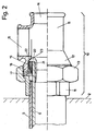
- a plastic tube 9 is arranged approximately coaxially in the interior of the jacket tube 5 and is connected to a medium supply source, for example a gas source, and is connected to the jacket tube 5 in a gas-tight and watertight manner adjacent to the inner surface 2 with a transition part 10, which is shown in FIG. 2 is shown on a larger scale.
- a medium supply source for example a gas source
- the transition part 10 mainly consists of a T-piece 11, the first opening 12 of which is gas-tight with the jacket tube 5 and the tube by means of a union nut 13 Plastic tube 9 is screwed.
- the T-piece 11 is provided on the second, axially opposite opening 14 with a screw closure, not shown, which can be unscrewed for cleaning the house entry 4 or the plastic pipe 9.
- the third. Opening 15 of the T-piece 11 serves to receive a pipe or valve for supplying the medium, preferably gas or water, to the interior of the building.
- the casing tube 5 When building the house wall 1 or later, the casing tube 5 is used and cemented. When the medium connection is to be established, the plastic tube 9 is displaced from the inside or outside through the jacket tube 5. Thereafter, an insert 16 pushed through the union nut 13 is screwed gas-tight onto the casing tube 5 and the union nut 13 is displaced as far as possible towards the inner surface 2. Then a spring washer seal 17, a wedge ring 18 and an annular seal 19 are moved over the exposed end of the plastic tube 9. A support nipple 20 is then hammered into the end 21 of the plastic tube 9.
- the support nipple is provided on the outside with ring-shaped barbs, which hold the support nipple 20 after driving in such a way that it can practically no longer be pulled out.
- the support nipple 20 thus holds the parts 17, 18 and 19 in such a way that they cannot be removed from the plastic tube 9.
- the T-piece 11 or its first opening 12 is moved over the parts 18 and 19 against the spring washer seal 17 and the union nut 13 is brought into engagement with the external thread of the T-piece 11 around the first opening 12 and tightened.
- the seal 17 presses the wedge ring 18 over the ring seal 19, so that a gas-tight connection is created.
- the annular surface 22 of the T-piece 11 presses against the annular surface 23 on the support nipple 20, so that a gas-tight connection is created.
- the parts 18-20 z. B. consist of plastic, but the spring washer seal 17 is made of metal or another refractory material, so that a completely metallic or otherwise fireproof shielding of the plastic tube 9 is guaranteed against fire.
- the casing tube 5 can, for. B. also consist of asbestos, concrete, brick, ceramic or Eternitt. Furthermore, the tube 5, for. B. in conversions, consist of an existing metal feed pipe that has been cut to the appropriate length. This z. B. masonry avoided. This solution is always possible if the existing, already walled-in pipe has a sufficient diameter.
- the house entry described is very easy to assemble, monitor and repair. If, for example, the plastic pipe has to be replaced for any reason, it is possible without replacing the casing pipe.
- connection work Since the transition from the plastic to the steel pipe is inside the building, the connection work is very easy and can be carried out under pleasant working conditions.
Claims (8)
Priority Applications (1)
| Application Number | Priority Date | Filing Date | Title |
|---|---|---|---|
| AT81103830T ATE3666T1 (de) | 1980-05-23 | 1981-05-19 | Hauseinfuehrung, fuer medium-transportleitungen insbesondere fuer gas- und wasserleitungen. |
Applications Claiming Priority (2)
| Application Number | Priority Date | Filing Date | Title |
|---|---|---|---|
| CH4035/80 | 1980-05-23 | ||
| CH403580 | 1980-05-23 |
Publications (2)
| Publication Number | Publication Date |
|---|---|
| EP0040791A1 EP0040791A1 (fr) | 1981-12-02 |
| EP0040791B1 true EP0040791B1 (fr) | 1983-06-01 |
Family
ID=4268588
Family Applications (1)
| Application Number | Title | Priority Date | Filing Date |
|---|---|---|---|
| EP81103830A Expired EP0040791B1 (fr) | 1980-05-23 | 1981-05-19 | Introduction dans la maison de tuyauteries de fluide, notamment pour conduits de gaz et d'eau |
Country Status (3)
| Country | Link |
|---|---|
| EP (1) | EP0040791B1 (fr) |
| AT (1) | ATE3666T1 (fr) |
| DE (1) | DE3160387D1 (fr) |
Cited By (1)
| Publication number | Priority date | Publication date | Assignee | Title |
|---|---|---|---|---|
| EP2270377A1 (fr) | 2009-07-02 | 2011-01-05 | Georg Fischer Fittings GmbH | Entrée de maison |
Families Citing this family (3)
| Publication number | Priority date | Publication date | Assignee | Title |
|---|---|---|---|---|
| CH651367A5 (de) * | 1981-08-25 | 1985-09-13 | Fischer Ag Georg | Gebaeudewanddurchfuehrung fuer versorgungsleitungen, insbesondere fuer gas und wasser. |
| DE3633353C2 (de) * | 1986-10-01 | 1995-01-05 | Manibs Spezialarmaturen | Klemmverbinder für Druckrohrleitungen aus Kunststoff |
| AUPN023694A0 (en) * | 1994-12-22 | 1995-01-27 | H.P.H. Pty. Ltd. | A fluid apron |
Family Cites Families (6)
| Publication number | Priority date | Publication date | Assignee | Title |
|---|---|---|---|---|
| DE1801908A1 (de) * | 1968-10-09 | 1970-06-18 | Borm Walter | Dichtungsanordnung an Wanddurchfuehrungen,Schutzrohren u.dgl.,insbesondere fuer Kunststoffrohrleitungen |
| DE2352571C2 (de) * | 1973-10-17 | 1975-06-12 | Main-Gaswerke Ag, 6000 Frankfurt | Verbindung einer Gasrohrleitung aus Polyaethylen mit einer metallischen Gasrohrleitung |
| AT339102B (de) * | 1974-08-16 | 1977-10-10 | Main Gaswerke A G | Verbindung einer gasrohrleitung aus polyathylen mit einer metallischen gasrohrleitung |
| GB1491154A (en) * | 1976-07-23 | 1977-11-09 | British Gas Corp | Pipe couplings |
| DE2644599C3 (de) * | 1976-10-02 | 1981-03-19 | Main-Gaswerke Ag, 6000 Frankfurt | Feuersichere Hausanschluß-Gasleitung |
| GB1557813A (en) * | 1977-01-31 | 1979-12-12 | Crane Ltd | Pipe connector |
-
1981
- 1981-05-19 AT AT81103830T patent/ATE3666T1/de not_active IP Right Cessation
- 1981-05-19 EP EP81103830A patent/EP0040791B1/fr not_active Expired
- 1981-05-19 DE DE8181103830T patent/DE3160387D1/de not_active Expired
Cited By (1)
| Publication number | Priority date | Publication date | Assignee | Title |
|---|---|---|---|---|
| EP2270377A1 (fr) | 2009-07-02 | 2011-01-05 | Georg Fischer Fittings GmbH | Entrée de maison |
Also Published As
| Publication number | Publication date |
|---|---|
| EP0040791A1 (fr) | 1981-12-02 |
| DE3160387D1 (en) | 1983-07-07 |
| ATE3666T1 (de) | 1983-06-15 |
Similar Documents
| Publication | Publication Date | Title |
|---|---|---|
| EP0603775B1 (fr) | Méthode pour effectuer des connexions étanches entre un tuyau et un raccord de tuyau, et un raccord de tuyau serrable utilisé à cet effet | |
| EP0040791B1 (fr) | Introduction dans la maison de tuyauteries de fluide, notamment pour conduits de gaz et d'eau | |
| DE3308877C2 (fr) | ||
| EP0975914A1 (fr) | Derivation vissable pour tuyaux a regard a fine paroi | |
| DE19816253A1 (de) | Rohrstopfen mit Sicherungsring | |
| DE8525261U1 (de) | Verlängerbarer Verbinder für hydraulische Anlagen | |
| DE2934491C2 (de) | Mauerdurchführung | |
| EP0073049B1 (fr) | Introduction de bâtiments pour distribution à tuyauteries, particulièrement pour gaz et eau | |
| CH650578A5 (de) | Rohranschluss fuer konzentrische rohre. | |
| DE8014568U1 (de) | Vorrichtung zur einfuehrung eines gasrohres | |
| DE4242236C1 (de) | Mauerdurchführung | |
| DE4344077C1 (de) | Mauerdurchführung | |
| DE3020613A1 (de) | Vorrichtung zur einfuehrung eines gasrohres | |
| DE19641923A1 (de) | Vorrichtung zur Sanierung von Gasleitungen | |
| DE3800731C1 (en) | Angle-adjustable pipe bends comprising at least two pieces | |
| DE19641926C2 (de) | Vorrichtung zur Sanierung von Gasleitungen | |
| AT397115B (de) | Durchführung eines zu- oder ablaufrohres | |
| DE10115676B4 (de) | Verfahren und Vorrichtung zum nachträglichen Einbau eines Gasströmungswächters in eine Hausanschlußleitung | |
| DE3404409A1 (de) | Sicherheits-absperreinrichtung fuer rohrleitungen | |
| DD268041A1 (de) | Dichtende durchfuehrung fuer eine rohrleitung in einer dicken betonmauer innerhalb eines in der betonmauer einbetonierten rohres | |
| DE4244127A1 (de) | Vorrichtung zum dichtschließenden Verbinden eines Kanals mit einem Anschlußrohr und Verfahren zu ihrer Herstellung | |
| EP0611912A1 (fr) | Méthode de réalisation d'une connextion entre un tuyau principal et un tuyau de branchement et appareil pour sa mise en oeuvre | |
| DD201620A5 (de) | Verbindungselement zwischen einer plastleitung fuer fluide unter druck und einer metallischen leitung | |
| DE3137792A1 (de) | Hausanschluss-gasleitung | |
| DE8424845U1 (de) | Mauerdurchfuehrungsarmatur zum anschliessen einer kunststoff-gaszuleitung an eine metall-hausleitung |
Legal Events
| Date | Code | Title | Description |
|---|---|---|---|
| PUAI | Public reference made under article 153(3) epc to a published international application that has entered the european phase |
Free format text: ORIGINAL CODE: 0009012 |
|
| AK | Designated contracting states |
Designated state(s): AT BE CH DE FR GB IT LU NL SE |
|
| 17P | Request for examination filed |
Effective date: 19820113 |
|
| ITF | It: translation for a ep patent filed |
Owner name: STUDIO ING. ALFREDO RAIMONDI |
|
| GRAA | (expected) grant |
Free format text: ORIGINAL CODE: 0009210 |
|
| AK | Designated contracting states |
Designated state(s): AT BE CH DE FR GB IT LI LU NL SE |
|
| REF | Corresponds to: |
Ref document number: 3666 Country of ref document: AT Date of ref document: 19830615 Kind code of ref document: T |
|
| REF | Corresponds to: |
Ref document number: 3160387 Country of ref document: DE Date of ref document: 19830707 |
|
| ET | Fr: translation filed | ||
| PLBE | No opposition filed within time limit |
Free format text: ORIGINAL CODE: 0009261 |
|
| STAA | Information on the status of an ep patent application or granted ep patent |
Free format text: STATUS: NO OPPOSITION FILED WITHIN TIME LIMIT |
|
| 26N | No opposition filed | ||
| PGFP | Annual fee paid to national office [announced via postgrant information from national office to epo] |
Ref country code: FR Payment date: 19910416 Year of fee payment: 11 |
|
| PGFP | Annual fee paid to national office [announced via postgrant information from national office to epo] |
Ref country code: DE Payment date: 19910418 Year of fee payment: 11 |
|
| PGFP | Annual fee paid to national office [announced via postgrant information from national office to epo] |
Ref country code: GB Payment date: 19910419 Year of fee payment: 11 Ref country code: BE Payment date: 19910419 Year of fee payment: 11 |
|
| PGFP | Annual fee paid to national office [announced via postgrant information from national office to epo] |
Ref country code: SE Payment date: 19910425 Year of fee payment: 11 Ref country code: LU Payment date: 19910425 Year of fee payment: 11 Ref country code: AT Payment date: 19910425 Year of fee payment: 11 |
|
| ITTA | It: last paid annual fee | ||
| PGFP | Annual fee paid to national office [announced via postgrant information from national office to epo] |
Ref country code: NL Payment date: 19910531 Year of fee payment: 11 |
|
| PGFP | Annual fee paid to national office [announced via postgrant information from national office to epo] |
Ref country code: CH Payment date: 19910819 Year of fee payment: 11 |
|
| EPTA | Lu: last paid annual fee | ||
| PG25 | Lapsed in a contracting state [announced via postgrant information from national office to epo] |
Ref country code: LU Free format text: LAPSE BECAUSE OF NON-PAYMENT OF DUE FEES Effective date: 19920519 Ref country code: GB Effective date: 19920519 Ref country code: AT Effective date: 19920519 |
|
| PG25 | Lapsed in a contracting state [announced via postgrant information from national office to epo] |
Ref country code: SE Effective date: 19920520 |
|
| PG25 | Lapsed in a contracting state [announced via postgrant information from national office to epo] |
Ref country code: DE Effective date: 19920521 |
|
| PG25 | Lapsed in a contracting state [announced via postgrant information from national office to epo] |
Ref country code: LI Effective date: 19920531 Ref country code: CH Effective date: 19920531 Ref country code: BE Effective date: 19920531 |
|
| BERE | Be: lapsed |
Owner name: GEORG FISCHER A.G. Effective date: 19920531 |
|
| PG25 | Lapsed in a contracting state [announced via postgrant information from national office to epo] |
Ref country code: NL Effective date: 19921201 |
|
| GBPC | Gb: european patent ceased through non-payment of renewal fee |
Effective date: 19920519 |
|
| NLV4 | Nl: lapsed or anulled due to non-payment of the annual fee | ||
| PG25 | Lapsed in a contracting state [announced via postgrant information from national office to epo] |
Ref country code: FR Effective date: 19930129 |
|
| REG | Reference to a national code |
Ref country code: CH Ref legal event code: PL |
|
| REG | Reference to a national code |
Ref country code: FR Ref legal event code: ST |
|
| EUG | Se: european patent has lapsed |
Ref document number: 81103830.6 Effective date: 19921204 |