EP0040291A2 - Articulation de prothèse pour amputés du genou et de la cuisse - Google Patents
Articulation de prothèse pour amputés du genou et de la cuisse Download PDFInfo
- Publication number
- EP0040291A2 EP0040291A2 EP81100947A EP81100947A EP0040291A2 EP 0040291 A2 EP0040291 A2 EP 0040291A2 EP 81100947 A EP81100947 A EP 81100947A EP 81100947 A EP81100947 A EP 81100947A EP 0040291 A2 EP0040291 A2 EP 0040291A2
- Authority
- EP
- European Patent Office
- Prior art keywords
- piece
- shaft
- joint according
- guide
- carrier
- Prior art date
- Legal status (The legal status is an assumption and is not a legal conclusion. Google has not performed a legal analysis and makes no representation as to the accuracy of the status listed.)
- Granted
Links
Images

Classifications
-
- A—HUMAN NECESSITIES
- A61—MEDICAL OR VETERINARY SCIENCE; HYGIENE
- A61F—FILTERS IMPLANTABLE INTO BLOOD VESSELS; PROSTHESES; DEVICES PROVIDING PATENCY TO, OR PREVENTING COLLAPSING OF, TUBULAR STRUCTURES OF THE BODY, e.g. STENTS; ORTHOPAEDIC, NURSING OR CONTRACEPTIVE DEVICES; FOMENTATION; TREATMENT OR PROTECTION OF EYES OR EARS; BANDAGES, DRESSINGS OR ABSORBENT PADS; FIRST-AID KITS
- A61F2/00—Filters implantable into blood vessels; Prostheses, i.e. artificial substitutes or replacements for parts of the body; Appliances for connecting them with the body; Devices providing patency to, or preventing collapsing of, tubular structures of the body, e.g. stents
- A61F2/50—Prostheses not implantable in the body
- A61F2/60—Artificial legs or feet or parts thereof
- A61F2/64—Knee joints
Definitions
- the invention relates to a prosthetic joint for knee and thigh amputee, which consists of a hollow shaft open on the upper side for receiving the thigh stump and an attachment piece articulated to this shaft for fastening an artificial calf with a foot part.
- the shaft is produced by means of a cast of the intact thigh stump and is then pushed over this stump in use and firmly connected to it with the aid of holding straps or the like in a manner known per se.
- a pipe adapter is attached to the extension piece, which is coated with a so-called cosmetic made of foam.
- the prosthesis joints previously used for this purpose are on the one hand too heavy and therefore annoying to wear.
- the known prosthesis joints have the disadvantage that when the artificial lower leg is angled it can be clearly seen that it is a prosthesis.
- These known prosthesis joints are angled, length differences between a healthy leg and the prosthesis become visible and sharp edges or protrusions emerge at the front at the point where the knee cap sits on the natural leg.
- the invention is therefore based on the object of creating an improved prosthesis joint for knee and thigh amputee which does not have these disadvantages, ie is light in weight and is nevertheless stable, is more dynamic in the gait phase and enables better so-called cosmetics.
- the articulated connection is a guide piece which is fixedly connected to the extension piece and has straight guide grooves, a slide piece which is guided by this slide piece, a support which is displaceably guided by means of an arc-shaped guide strip and which is fixedly connected to the shaft and a between the arc-shaped one Carrier on the one hand and the guide piece on the other hand arranged gear transmission.
- This gear transmission consists of an arc-shaped rack on the carrier, a straight rack on the guide piece and a pinion rotatably mounted in the slide, which meshes with the two racks.
- this prosthesis joint is a so-called rotating-sliding joint. It is therefore not only a simple rotary movement about a fixed axis, but at the same time the special arrangement of the gear mechanism forces the slider and thus the shaft to be advanced.
- the pinion be two in addition has each other and coaxially arranged gears with different pitch circle diameters, one of which meshes with the circular rack on the carrier and the other meshes with the rectilinear rack on the guide piece. In this way, a reduction or translation can be achieved in a simple manner and the anatomically correct feed of the sliding piece and thus of the shaft can be realized.
- one of the two gears consists of two halves which are arranged on both sides of the other gear.
- Two gear racks are then assigned to the two gear wheel halves.
- all known holding means can be used.
- the support attached to the shaft is encompassed on both sides by the slider in a C-shape.
- the slider and / or the guide piece and / or the carrier 5 are made of materials with low mutual friction values, preferably plastics. In this case, special lubrication can be dispensed with, which would otherwise lead to problems with contamination of the trouser leg.
- stops are attached to the front and rear ends of the guide piece.
- an elastic band covering the front of the prosthesis is provided, which is attached to the upper side of the shaft and the underside of the extension piece and covers these two parts over a greater length, but above all covers the components of the prosthetic joint.
- the artificial lower leg can be connected to the extension piece in a manner known per se.
- a holding mandrel is preferably provided there for the adjustable attachment, which widens conically downward and enables alignment and adjustment of the artificial lower leg to a certain extent with the aid of counterparts known per se.
- a further adjustment in the lateral direction is possible in that a number of several rows of threaded bores arranged at uniform intervals are provided in the guide piece. You can then screw the extension piece more or less laterally offset depending on the static conditions.
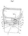
- the prosthesis joint consists of a hollow shaft 1 which is open on the upper side and which is pushed onto the stump 2 and firmly connected to it in a manner known per se.
- the connection is further improved by the retaining grooves made in the shaft.
- the shaft is made of plastic and was previously made after a cast of the thigh stump.
- the joint further comprises an extension piece 3, which consists of a holding plate and a holding mandrel 4, which is connected in one piece on the underside, and which has an adjustable fastening of the artificial lower leg 2 allowed.
- the prosthetic joint further comprises an articulated connection between the shaft 1 and the attachment piece 3.
- This articulated connection consists of a guide piece 5 which is fixedly connected to the attachment piece and has straight guide grooves 17.
- the extension piece 3 as can be seen from FIG. 1, is screwed to the guide piece by means of fastening screws 19a and 19b. The screws are screwed into those threaded bores 20 in a reinforcing plate 21 made of metal which is inserted into the guide piece and which give the extension piece 3 the correct position.
- the articulated connection is formed by an arcuate support with laterally projecting circular guide strips 18a and 18b.
- This carrier is attached to the lower end of the shaft 1 at the rear.
- said guide strips are encompassed in a C-shape by the correspondingly grooved slider 6.
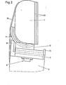
- the slider is provided on the underside with outwardly projecting guide strips which engage in corresponding guide grooves 17a and 17b in the guide piece 5. These guide strips and guide grooves are rectilinear and allow the slider 6 to be displaced in a straight line relative to the guide piece 5, as can be seen by comparing FIGS. 1 and 2.
- a gear mechanism which is arranged between the aforementioned parts, serves to inevitably assign the feed movement to the swivel movement.
- this gear consists of an arc-shaped toothed rack 8 in the carrier, specifically in the middle between the two circular guide strips 18a and 18b projecting from it laterally.
- the gear transmission also consists of a pinion 9, which is rotatably seated on a fixed axis 16, which is clamped via plastic clamping sleeves 15a and 15b in corresponding holding slots 14a and 14b in the slider 6.
- the toothed pinion meshes on the upper side with the circular rack 8 of the carrier 7, but on the other hand also with a rectilinear rack 10, which is located in the guide piece 5, between its two guide grooves 17a and 17b.
- the joint is covered by an elastic band 13, which is firmly connected at both ends to the shaft or the extension piece and covers the gap between these two parts.
- a gear transmission with a different transmission ratio comprises an arc-shaped rack 108 in the carrier 107, a gear 109c meshing with this rack, which sits loosely on a fixed axis 116, which is again arranged in corresponding holding slots of the slide 106 by clamping sleeves 115a and 115b and is firmly connected to this slide.
- circular guide strips 118a and 118b on the slide piece 106 engage in correspondingly shaped guide grooves in the carrier 107, while on the other hand straight guide grooves 117a and 117b in the guide piece 105 accommodate the corresponding guide strips which project outwards from the slide piece 106 on the underside.
- prosthetic joint according to the invention can be used for knee and thigh amputees with different thigh sizes, in that the shaft can be produced in different sizes.
Landscapes
- Health & Medical Sciences (AREA)
- Transplantation (AREA)
- Biomedical Technology (AREA)
- Cardiology (AREA)
- Oral & Maxillofacial Surgery (AREA)
- Engineering & Computer Science (AREA)
- Orthopedic Medicine & Surgery (AREA)
- Heart & Thoracic Surgery (AREA)
- Vascular Medicine (AREA)
- Life Sciences & Earth Sciences (AREA)
- Animal Behavior & Ethology (AREA)
- General Health & Medical Sciences (AREA)
- Public Health (AREA)
- Veterinary Medicine (AREA)
- Prostheses (AREA)
Priority Applications (1)
| Application Number | Priority Date | Filing Date | Title |
|---|---|---|---|
| US06/268,719 US4379350A (en) | 1981-02-11 | 1981-06-01 | Prosthetic joint for knee and above-knee amputees |
Applications Claiming Priority (2)
| Application Number | Priority Date | Filing Date | Title |
|---|---|---|---|
| DE19803019048 DE3019048A1 (de) | 1980-05-19 | 1980-05-19 | Prothesengelenk fuer unterschenkelamputierte |
| DE3019048 | 1980-05-19 |
Publications (3)
| Publication Number | Publication Date |
|---|---|
| EP0040291A2 true EP0040291A2 (fr) | 1981-11-25 |
| EP0040291A3 EP0040291A3 (en) | 1982-03-31 |
| EP0040291B1 EP0040291B1 (fr) | 1986-05-28 |
Family
ID=6102757
Family Applications (1)
| Application Number | Title | Priority Date | Filing Date |
|---|---|---|---|
| EP81100947A Expired EP0040291B1 (fr) | 1980-05-19 | 1981-02-11 | Articulation de prothèse pour amputés du genou et de la cuisse |
Country Status (7)
| Country | Link |
|---|---|
| US (1) | US4312081A (fr) |
| EP (1) | EP0040291B1 (fr) |
| BE (1) | BE884627A (fr) |
| DE (2) | DE3019048A1 (fr) |
| FR (1) | FR2482449A1 (fr) |
| GB (1) | GB2075842A (fr) |
| NL (1) | NL8004615A (fr) |
Families Citing this family (4)
| Publication number | Priority date | Publication date | Assignee | Title |
|---|---|---|---|---|
| US4379350A (en) * | 1981-02-11 | 1983-04-12 | Munny Guenter | Prosthetic joint for knee and above-knee amputees |
| SE446373B (sv) * | 1983-06-15 | 1986-09-08 | Landstingens Inkopscentral | Instellbart forbindningselement for protesdelar |
| US5895430A (en) * | 1998-02-06 | 1999-04-20 | O'connor; Roderick S. | Prosthesis for long femur and knee disarticulation amputation |
| DE102011083388B4 (de) * | 2010-11-26 | 2017-01-05 | Guido Wohlgemuth | Gelenkprothese |
Family Cites Families (15)
| Publication number | Priority date | Publication date | Assignee | Title |
|---|---|---|---|---|
| DE8013429U1 (de) * | 1980-08-14 | Sanitaetshaus Guenter Munny Gmbh, 5060 Bergisch Gladbach | Prothesengelenk für Unterschenkelamputierte | |
| DE570181C (de) * | 1928-05-31 | 1933-02-13 | Thomas Oesterle | Kuenstliches Bein |
| US2046069A (en) * | 1932-01-02 | 1936-06-30 | Greissinger Georg | Knee joint for artificial legs |
| DE749004C (de) * | 1942-04-28 | 1952-04-17 | Ad Krauth Inh Th Widensohler | Kniegelenk fuer kuenstliche Beine |
| US2457482A (en) * | 1946-03-25 | 1948-12-28 | Marean Kostandean | Artificial leg |
| DE828292C (de) * | 1948-05-10 | 1952-01-17 | Alois Novotny | Kniegelenk fuer Beinprothesen |
| DE807536C (de) * | 1948-10-02 | 1951-07-02 | Orthopaediewerk Habermann G M | Kuenstliches Kniegelenk |
| DE831871C (de) * | 1950-04-25 | 1952-02-18 | Matthias Lehrner | Unterschenkelprothese |
| DE851394C (de) * | 1951-01-09 | 1952-10-02 | Hans Scheefers | Kniegelenkschuetzer aus Gummi mit Schmiernippel fuer Kunstbeine und Stuetzapparate |
| FR1046195A (fr) * | 1951-12-06 | 1953-12-03 | Proteor Sa | Perfectionnements aux articulations de genou pour jambes artificielles |
| US2883982A (en) * | 1956-09-06 | 1959-04-28 | Fred E Rainey | Leg brace |
| GB978586A (en) * | 1962-09-21 | 1964-12-23 | Vessa Ltd | Improvements in artificial legs |
| DE1800500C3 (de) * | 1968-10-02 | 1974-05-09 | Teufel, Wilhelm Julius, 7000 Stuttgart | Verstellbare Rohrskelett-Beinprothese |
| NL148231B (nl) * | 1974-02-20 | 1976-01-15 | Stichting Revalidatie Inst | Beenprothese. |
| US4085466A (en) * | 1974-11-18 | 1978-04-25 | National Research Development Corporation | Prosthetic joint device |
-
1980
- 1980-05-19 DE DE19803019048 patent/DE3019048A1/de not_active Withdrawn
- 1980-07-25 US US06/172,160 patent/US4312081A/en not_active Expired - Lifetime
- 1980-07-31 FR FR8016898A patent/FR2482449A1/fr not_active Withdrawn
- 1980-08-04 BE BE0/201644A patent/BE884627A/fr unknown
- 1980-08-14 NL NL8004615A patent/NL8004615A/nl not_active Application Discontinuation
- 1980-09-25 GB GB8030922A patent/GB2075842A/en not_active Withdrawn
-
1981
- 1981-02-11 DE DE8181100947T patent/DE3174685D1/de not_active Expired
- 1981-02-11 EP EP81100947A patent/EP0040291B1/fr not_active Expired
Also Published As
| Publication number | Publication date |
|---|---|
| BE884627A (fr) | 1980-12-01 |
| DE3019048A1 (de) | 1981-11-26 |
| NL8004615A (nl) | 1981-12-16 |
| FR2482449A1 (fr) | 1981-11-20 |
| GB2075842A (en) | 1981-11-25 |
| US4312081A (en) | 1982-01-26 |
| EP0040291A3 (en) | 1982-03-31 |
| EP0040291B1 (fr) | 1986-05-28 |
| DE3174685D1 (en) | 1986-07-03 |
Similar Documents
| Publication | Publication Date | Title |
|---|---|---|
| EP0010177B1 (fr) | Genouillère artificielle | |
| DE2754422C2 (de) | Bremsanordnung für eine Kniegelenkprothese | |
| DE2742112A1 (de) | Halter fuer eine handbrause | |
| DE2539023B2 (de) | Gelenkbeschlag für Sitze | |
| DE3029955C2 (de) | Kettenschaltung für Fahrräder | |
| AT395368B (de) | Skischuh | |
| DE2900527A1 (de) | Skibremse | |
| DE60214274T2 (de) | Snowboardbindung | |
| DE2757055B2 (de) | Automatisch arbeitende Beschickungsvorrichtung für Rohlinge von Kartuschenhülsen o.a. Teile | |
| DE2152408B2 (de) | Physiologisches kniegelenk fuer eine rohrskelett-prothese | |
| DE2447811C2 (de) | Scharnier mit einem an einem Möbelteil befestigbaren Grundkörper | |
| EP0040291B1 (fr) | Articulation de prothèse pour amputés du genou et de la cuisse | |
| DE1962627B2 (de) | Handduschenhalterung | |
| DE2365415C2 (de) | Abstreifvorrichtung für Gurtbänder | |
| DE2152569A1 (de) | Handbetaetigter Papierlocher | |
| DE3127446A1 (de) | Verfahren zum anbringen und halten eines duennen, flexiblen streifens innerhalb einer brillengestellfassung | |
| DE2701842A1 (de) | Skibindung mit einer beweglichen platte zur aufnahme des entsprechenden schuhs | |
| DE69103340T2 (de) | Krümmungsgerät für Zahnwurzelkanalhandwerkzeug. | |
| DE3919430A1 (de) | Skistiefel | |
| DE2052340C3 (de) | Dentalapparat | |
| DE1678302A1 (de) | Backen einer Ausloeseskibindung | |
| DE8013429U1 (de) | Prothesengelenk für Unterschenkelamputierte | |
| DE2821101B2 (de) | Auszugführung für in einem Gestell gehaltene Schubladen o.dgl | |
| EP0039470A2 (fr) | Vis d'allongement transversale variable | |
| DE2521746A1 (de) | Skibindung mit laengsverstellvorrichtung |
Legal Events
| Date | Code | Title | Description |
|---|---|---|---|
| PUAI | Public reference made under article 153(3) epc to a published international application that has entered the european phase |
Free format text: ORIGINAL CODE: 0009012 |
|
| AK | Designated contracting states |
Designated state(s): BE CH DE FR GB NL |
|
| 17P | Request for examination filed |
Effective date: 19811019 |
|
| PUAL | Search report despatched |
Free format text: ORIGINAL CODE: 0009013 |
|
| AK | Designated contracting states |
Designated state(s): BE CH DE FR GB NL |
|
| GRAA | (expected) grant |
Free format text: ORIGINAL CODE: 0009210 |
|
| AK | Designated contracting states |
Kind code of ref document: B1 Designated state(s): BE CH DE FR GB LI NL |
|
| REF | Corresponds to: |
Ref document number: 3174685 Country of ref document: DE Date of ref document: 19860703 |
|
| ET | Fr: translation filed | ||
| PGFP | Annual fee paid to national office [announced via postgrant information from national office to epo] |
Ref country code: NL Payment date: 19870228 Year of fee payment: 7 |
|
| PLBE | No opposition filed within time limit |
Free format text: ORIGINAL CODE: 0009261 |
|
| STAA | Information on the status of an ep patent application or granted ep patent |
Free format text: STATUS: NO OPPOSITION FILED WITHIN TIME LIMIT |
|
| 26N | No opposition filed | ||
| PG25 | Lapsed in a contracting state [announced via postgrant information from national office to epo] |
Ref country code: GB Effective date: 19890211 |
|
| PG25 | Lapsed in a contracting state [announced via postgrant information from national office to epo] |
Ref country code: LI Effective date: 19890228 Ref country code: CH Effective date: 19890228 Ref country code: BE Effective date: 19890228 |
|
| BERE | Be: lapsed |
Owner name: SANITATSHAUS GUNTER MUNNY G.M.B.H. Effective date: 19890228 |
|
| PG25 | Lapsed in a contracting state [announced via postgrant information from national office to epo] |
Ref country code: NL Effective date: 19890901 |
|
| NLV4 | Nl: lapsed or anulled due to non-payment of the annual fee | ||
| GBPC | Gb: european patent ceased through non-payment of renewal fee | ||
| PG25 | Lapsed in a contracting state [announced via postgrant information from national office to epo] |
Ref country code: FR Free format text: LAPSE BECAUSE OF NON-PAYMENT OF DUE FEES Effective date: 19891027 |
|
| REG | Reference to a national code |
Ref country code: CH Ref legal event code: PL |
|
| PG25 | Lapsed in a contracting state [announced via postgrant information from national office to epo] |
Ref country code: DE Effective date: 19891101 |
|
| REG | Reference to a national code |
Ref country code: FR Ref legal event code: ST |