EP0038499A1 - System zum optischen Schreiben und Lesen - Google Patents
System zum optischen Schreiben und Lesen Download PDFInfo
- Publication number
- EP0038499A1 EP0038499A1 EP81102786A EP81102786A EP0038499A1 EP 0038499 A1 EP0038499 A1 EP 0038499A1 EP 81102786 A EP81102786 A EP 81102786A EP 81102786 A EP81102786 A EP 81102786A EP 0038499 A1 EP0038499 A1 EP 0038499A1
- Authority
- EP
- European Patent Office
- Prior art keywords
- disc
- recording
- optical recording
- film
- guide track
- Prior art date
- Legal status (The legal status is an assumption and is not a legal conclusion. Google has not performed a legal analysis and makes no representation as to the accuracy of the status listed.)
- Granted
Links
- 230000003287 optical effect Effects 0.000 title claims abstract description 20
- 238000002834 transmittance Methods 0.000 claims abstract description 5
- 239000000463 material Substances 0.000 claims description 31
- 239000011347 resin Substances 0.000 claims description 11
- 229920005989 resin Polymers 0.000 claims description 11
- 239000010410 layer Substances 0.000 claims description 4
- 239000011241 protective layer Substances 0.000 claims description 3
- 239000010408 film Substances 0.000 description 41
- 238000010276 construction Methods 0.000 description 12
- 230000000694 effects Effects 0.000 description 10
- 238000000034 method Methods 0.000 description 5
- 239000004065 semiconductor Substances 0.000 description 4
- 238000001704 evaporation Methods 0.000 description 3
- 230000008020 evaporation Effects 0.000 description 3
- 230000035945 sensitivity Effects 0.000 description 3
- 229910052714 tellurium Inorganic materials 0.000 description 3
- PORWMNRCUJJQNO-UHFFFAOYSA-N tellurium atom Chemical compound [Te] PORWMNRCUJJQNO-UHFFFAOYSA-N 0.000 description 3
- -1 acryl Chemical group 0.000 description 2
- 230000005540 biological transmission Effects 0.000 description 2
- 238000005336 cracking Methods 0.000 description 2
- 238000005553 drilling Methods 0.000 description 2
- 229920003229 poly(methyl methacrylate) Polymers 0.000 description 2
- 239000004926 polymethyl methacrylate Substances 0.000 description 2
- 230000001681 protective effect Effects 0.000 description 2
- 239000010409 thin film Substances 0.000 description 2
- 230000002087 whitening effect Effects 0.000 description 2
- CTQNGGLPUBDAKN-UHFFFAOYSA-N O-Xylene Chemical compound CC1=CC=CC=C1C CTQNGGLPUBDAKN-UHFFFAOYSA-N 0.000 description 1
- 239000004793 Polystyrene Substances 0.000 description 1
- 230000001464 adherent effect Effects 0.000 description 1
- 125000003118 aryl group Chemical group 0.000 description 1
- 238000011161 development Methods 0.000 description 1
- 230000018109 developmental process Effects 0.000 description 1
- 238000009826 distribution Methods 0.000 description 1
- 238000002474 experimental method Methods 0.000 description 1
- 238000002347 injection Methods 0.000 description 1
- 239000007924 injection Substances 0.000 description 1
- 238000004519 manufacturing process Methods 0.000 description 1
- 230000008018 melting Effects 0.000 description 1
- 238000002844 melting Methods 0.000 description 1
- 239000000203 mixture Substances 0.000 description 1
- 238000007254 oxidation reaction Methods 0.000 description 1
- 229920002223 polystyrene Polymers 0.000 description 1
- 229920000915 polyvinyl chloride Polymers 0.000 description 1
- 239000004800 polyvinyl chloride Substances 0.000 description 1
- 239000002904 solvent Substances 0.000 description 1
- 238000001771 vacuum deposition Methods 0.000 description 1
- 239000008096 xylene Substances 0.000 description 1
Images

Classifications
-
- G—PHYSICS
- G11—INFORMATION STORAGE
- G11B—INFORMATION STORAGE BASED ON RELATIVE MOVEMENT BETWEEN RECORD CARRIER AND TRANSDUCER
- G11B7/00—Recording or reproducing by optical means, e.g. recording using a thermal beam of optical radiation by modifying optical properties or the physical structure, reproducing using an optical beam at lower power by sensing optical properties; Record carriers therefor
- G11B7/24—Record carriers characterised by shape, structure or physical properties, or by the selection of the material
- G11B7/2407—Tracks or pits; Shape, structure or physical properties thereof
- G11B7/24073—Tracks
- G11B7/24079—Width or depth
-
- G—PHYSICS
- G11—INFORMATION STORAGE
- G11B—INFORMATION STORAGE BASED ON RELATIVE MOVEMENT BETWEEN RECORD CARRIER AND TRANSDUCER
- G11B7/00—Recording or reproducing by optical means, e.g. recording using a thermal beam of optical radiation by modifying optical properties or the physical structure, reproducing using an optical beam at lower power by sensing optical properties; Record carriers therefor
- G11B7/24—Record carriers characterised by shape, structure or physical properties, or by the selection of the material
- G11B7/26—Apparatus or processes specially adapted for the manufacture of record carriers
Definitions
- the present invention relates to a disc for optical record reproduction use and more particularly, a disc for optical record reproduction use, wherein a beam modulated by the information signal such as image signal or the like is applied upon the recording medium to form a recording film, which changes in reflectance or transmittance, on the recording medium layer due to the temperature change caused through the beam application.
- the film is drilled through the evaporation or melting by the laser beam.
- larger laser power is required and the hollow disc construction for providing a shelter for evaporation material is required to be provided.
- the thin film application of the latter has advantages in that the recording operation and the erasing operation can be performed with relative lower power.
- the latter has many problems yet to be settled. Cracks may be caused in the recording film due to decrease in the recording power and the heat during the recording operation, or the rest unerased may be likely to be caused during the erasing operation. These problems of the above are required to be settled.
- an object of the present invention is to provide a new disc which is free from the above-described problems, superior in terms of recording efficiency and recording bit positional accuracy.
- Another object of the present invention is to provide an optical disc having recording film formed, which changes in beam reflectance or beam transmittance without accompanying geometrical deformation, due to the raised temperatures through the laser beam application, on a disc-shaped base having geometrical rugged guide tracks formed in advance.
- a further object of the present invention is to provide an optical recording disc for focusingly applying laser beams on a recording member to record the information, in which concentrically or spirally convexed or concaved guide grooves are formed in advance on a disc-shaped resin base material of acryl or the like, a recording film which changes in reflectance or transmittance through the application of the light is formed on the entire face of the guide grooves.
- a still further object of the present-invention is to provide an optical recording disc for focusingly applying laser beams on a recording member to record the information, in which the guide grooves comprising geometrical rugged guide tracks are formed in advance on a disc-shaped resin base material of acryl or the like to form a recording film thereon, the film thickness of the stage difference is properly set to considerably improve the recording sensitivity and to remove the cracking phenomena during the recording operation, and the relationship between the groove width and the laser beam diameter is properly set to render the recording efficiency proper and to settle the rest unerased.
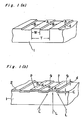
- Fig. l(a) shows one example of a disc base material 1, which is provided with optical convex-shaped guide grooves B.
- Fig. l(a) shows a partially enlarged disc base material, and the guide track A shown in Fig. l(a) is formed, in concentrical or spiral construction, almost uniformly on the entire face of at least an area for recording signals.
- the width W of the track A is different depending upon the wavelength of a light source to be used or the coherency degree thereof. When semiconductor laser of approximately 8000A in wavelength is used as a light source, approximately 0.7 through 1 pm is preferable.
- Reference character T shows a track pitch of the track A which is prescribed by the content of a signal to be recorded and reproduced and the amount of the tolerable crosstalk of a signal between the tracks.
- the track pitch T is set to a value of approximately 1.4 through 2.0 ⁇ m.
- the height difference d between the guide track A and the groove B, which is located between the tracks, is set to the depth of 1/6 through 1/12 of the wavelength ⁇ of the incident light so that asymmetrical diffraction effect may be provided with respect to light, which is applied upon the guide track A.
- the disc base material 1, which is provided with such convex-shaped or concave-shaped guide grooves B can be made with an art of making the original panel of the conventional video disc.
- Fig. l(b) shows a light sensitive recording material 2 (hereinafter referred to as light recording material) uniformly formed on the disc base material 1 shown in the Fig. l(a).
- the light recording material 2 is formed to the thickness in the range of several hundreds o 0 A through two thousands A although the thickness is different depending upon the types of the recording materials.
- the recording light L which is incident from the side of the base material is closed to a light beam whose diameter is equal to 0.7 through 1.0 pm (the width of the guide track A) or more.
- the track of Fig. l(b) can be followed with a tracking mirror.
- the base material 1 a material, which is optically homogeneous and transparent, such as polymethyl methacrylate resin, polyvinyl chloride resin or the like can be used.
- these resins can be used through the application of the conventional art of making the video disc as it was. Namely, grooves are formed by a hot press method or an injection method or the like. The groove layer can be provided on the base material 1 using these resins with the other resins such as ultraviolet hardening resin.
- sub-oxide light absorbing film such as film composed of TeOx (x ⁇ 1) can be applied. The film can be formed, by a vacuum evaporation method, to a given thickness independently of the ruggedness of the base material.
- Fig. 2(a) shows the construction corresponding to that of Fig. l(b).
- a laser beam is applied upon the recording film 2a disposed on the relatively concave portion A, which constitutes the guide track of the base material 1.
- the recording film 2a absorbs the laser light to increase the temperature.
- the heat quantity caused at this time moves to the other portion of the base material and the recording film 2a to make escape.
- Stage difference is provided between a portion indicated with 2a and a portion indicated with 2b.
- the disc construction has a recording film formed on the plane base plate which is not provided with grooves therein, and the heat of the laser light escapes in all the directions along the recording film, with the result that the temperature increasing efficiency of the laser beam application part is inferior, since the thermal conductivity of the recording film is 10 times or 100 times as compared with that of the resin base plate. Since the stage difference is caused in the film by this groove, the heat is correspondingly difficult to escape, with the result that the temperature is easily raised in the application position. Namely, the recording operation can be made with less laser power. According to the experiments of the inventors, cracks were caused in the film due to the raised temperature of the film during the recording operation in the case of the plane base plate free from grooves. However, no cracks were caused at all on such grooved disc of the embodiment of the present invention.
- the recording film, which is cut off in shape by the stage difference has an effect of reducing the thermal distortion.
- the track width W which most effectively raises the temperature by the laser beams.
- the convex shape which is constant in width and sufficiently long in length as a track A formed in concentric circle or spiral, will be described.
- the width W which is sufficiently greater as compared with the spot of the beam to be applied corresponds to a plane disc. Since the amount of film material per unit length becomes smaller as the width W becomes narrower, the thermal capacity reduces so that the temperature is likely to be raised. Also, since the contact area between the recording film and the base plate becomes smaller as the information track width W becomes narrower, the thermal transfer amount to the base plate becomes smaller. The temperature rise is better when the guide track width W is as wide as the thickness ⁇ of the light beam or is somewhat smaller than it.
- the thickness ⁇ of the light beam means effective beam diameter which has sufficient strength to change the characteristics of a recording material within the beam application face during no-signals.
- the effect is the same even when the guide track A is shaped to become relatively concave as shown in Fig. 2(b).
- the thermal conductivity of the base material is sufficiently smaller than that of the recording film, no difference is provided between the convex shape shown in Fig. 2(a) and the concave shape shown in Fig. 2(b).
- the width W of the track becomes narrower than the effective beam diameter w, difficulty is caused in terms of reproduction.
- the reflection light amount or transmission light amount caused by signals recorded on the track reduces, thus resulting in reduced S/N ratio.
- the guide track A is optimum to be approximately the same as wide as or slightly narrower than the effective beam diameter.
- the width of the guide track A is required to be in the range of 120% of the effective beam diameter and is preferred to be in the range of 110% of the effective beam.
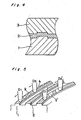
- the relationship between the thickness t of the recording film and the depth (height) d of the unevenness of the base material 1 will be described hereinafter.
- t ⁇ d When the relationship of t ⁇ d is established as shown in Fig. 3(a), the heat conduction within the recording film is cut off at the stage difference portion of the uneveness of the base material, and thus the above-described effect is greatest.
- t > d is established as shown in Fig..3 (b)
- the adiabatic effect can be expected except when t is sufficiently larger than d.
- the heat conduction of the recording film in the stage difference becomes half or less of the heat conduction of the plane so that with the result that the effect is large.
- the recording film is preferred to be at least two times as thick as the stage difference of the groove.
- PMMA of 1 mm in thickness was used as a grooved base material.
- the stage difference was 700 ⁇
- the width of the concave portion was 8000 ⁇
- the evaporated recording film was TeOx (x ⁇ 1) and 1400A in thickness.
- Fig. 4 shows an embodiment wherein the recording film 2 is covered with the other member 3 for the purpose of the mechanical protection. Even in this case, geometrical convexes or concaves are provided on the base material 1 as shown in the drawing, when the thermal conductivity of the protective member 3 is sufficiently small, to improve the recording sensitivity.
- An optically homogeneous resin such as polystyrene having thermal conductivity 0.8 through 1.2 x 10 -3 J/cm sec.°k is dissolved in the solvent of aromatic or the like such as xylene and is coated, dried thereby to provide the material 3.
- the recording film as extremely thin as approximately 1000 ⁇ . Since the film is heated during the recording operation, it is likely to be oxidized in a condition where it is exposed to air. Once it is oxidized, the transmission factor becomes layer in that portion. Transparency is distributed in accordance with the distribution of the temperature near the recording bit. Namely, blur is caused in the recording bit. This fact causes S/N to decrease in the case of the FM type recording. However, such adherent protective layer is formed to prevent the oxidization.
- the low oxide film of tellurium described hereinabove has an erasing property in certain composition conditions, as disclosed within the Japanese Patent Publication No. 3725/1979.
- the member is whitened at a portion where the slightly strong beam of the semiconductor laser is applied and is blackened at a portion where the beam weaker than it is applied.
- the whitening and blackening conditions can be provided through variation of the laser pulse width. Namely, the member is whitened through the short time application of the beam of 100 nsec. or less and is blackened through the long time application of the beam of 200 nsec or more. This whitening operation and blackening operation can be repeatedly performed.
- Fig. 5 is a view for illustrating an embodiment of the record erasure in such erasing disc as described hereinabove.
- a base material is generally at 1.
- a film for erasure recording use is generally designated at 2.
- a laser beam is generally designated at D 1 in a case where the writing-in operation has been effected with the laser of the beam diameter narrower than the width of the convex-shaped guide track.
- the laser beam for erasure use narrower than the guide track width is generally represented at D 2 .
- reference character g is a white bit signal written in.
- Reference character h is one portion of the white bit signal not erased.
- D 1 ', D 2 ', g' correspond to the above-described D 1 , D 2 and g.
- An example is shown where the diameter of the laser beam is almost the same as the width of the guide track or is slightly thicker than it. In this case, the rest unerased is not caused, since the laser beam runs along the track.
- the conditions of (W ⁇ w) of such beam diameter ⁇ and the groove width W as described hereinabvoe is provided from such erasing conditions as described hereinabove.
- the disc construction of the present invention can provide advantages in such a manner that the groove is formed and the film thickness of the stage difference is properly set to considerably improve the recording sensitivity and to remove the cracking phenomena during the recording operation.
- the relationship between the groove width and the laser beam diameter is properly set to render the recording efficiency proper and to settle the rest unerased.
Landscapes
- Engineering & Computer Science (AREA)
- Manufacturing & Machinery (AREA)
- Optical Record Carriers And Manufacture Thereof (AREA)
- Optical Recording Or Reproduction (AREA)
Applications Claiming Priority (2)
| Application Number | Priority Date | Filing Date | Title |
|---|---|---|---|
| JP49714/80 | 1980-04-15 | ||
| JP4971480A JPS56145535A (en) | 1980-04-15 | 1980-04-15 | Disc for optical recording |
Publications (2)
| Publication Number | Publication Date |
|---|---|
| EP0038499A1 true EP0038499A1 (de) | 1981-10-28 |
| EP0038499B1 EP0038499B1 (de) | 1987-09-09 |
Family
ID=12838849
Family Applications (1)
| Application Number | Title | Priority Date | Filing Date |
|---|---|---|---|
| EP81102786A Expired EP0038499B1 (de) | 1980-04-15 | 1981-04-11 | System zum optischen Schreiben und Lesen |
Country Status (4)
| Country | Link |
|---|---|
| US (1) | US4385303A (de) |
| EP (1) | EP0038499B1 (de) |
| JP (1) | JPS56145535A (de) |
| DE (1) | DE3176435D1 (de) |
Cited By (12)
| Publication number | Priority date | Publication date | Assignee | Title |
|---|---|---|---|---|
| FR2509891A1 (fr) * | 1981-07-17 | 1983-01-21 | Thomson Csf | Dispositif optique d'enregistrement-lecture sur support d'information pregrave |
| EP0077623A1 (de) * | 1981-10-09 | 1983-04-27 | Matsushita Electric Industrial Co., Ltd. | Optische Aufzeichnungs- und Wiedergabescheibe |
| FR2536895A1 (fr) * | 1982-11-25 | 1984-06-01 | Sony Corp | Support d'enregistrement optique |
| EP0124950A1 (de) * | 1983-05-09 | 1984-11-14 | Koninklijke Philips Electronics N.V. | Optisch schreibbarer und lesbarer Informationsträger |
| EP0132137A2 (de) * | 1983-07-14 | 1985-01-23 | Matsushita Electric Industrial Co., Ltd. | Platte zum Aufzeichnen und Wiedergeben von optischen Informationen |
| EP0136041A1 (de) * | 1983-08-18 | 1985-04-03 | Sharp Kabushiki Kaisha | Optische Speicherplatte |
| EP0163421A1 (de) * | 1984-04-27 | 1985-12-04 | Matsushita Electric Industrial Co., Ltd. | Verfahren zum Aufzeichnen und zum Löschen optischer Informationen |
| EP0200434A1 (de) * | 1985-04-18 | 1986-11-05 | Csk Corporation | Verfahren zum Lesen optisch aufgezeichneter Daten und Vorrichtung dafür |
| GB2198279A (en) * | 1986-10-23 | 1988-06-08 | Nec Corp | An optical storage medium |
| EP0376626A2 (de) * | 1988-12-27 | 1990-07-04 | Canon Kabushiki Kaisha | Optisches Informationsaufzeichnungsmittel mit trennendem Teil zwischen den Informationsspuren |
| EP0527602A2 (de) * | 1991-08-09 | 1993-02-17 | Sharp Kabushiki Kaisha | Optischer Speicher |
| DE19643214A1 (de) * | 1996-10-19 | 1998-04-30 | Fuji Magnetics Gmbh | Leitstrukturen in optischen Speichermedien |
Families Citing this family (23)
| Publication number | Priority date | Publication date | Assignee | Title |
|---|---|---|---|---|
| JPS581839A (ja) * | 1981-06-25 | 1983-01-07 | Akai Electric Co Ltd | 光記録媒体 |
| JPS59110053A (ja) * | 1982-12-13 | 1984-06-25 | Matsushita Electric Ind Co Ltd | 光メモリデイスクの製造方法 |
| JPS5911551A (ja) * | 1982-07-12 | 1984-01-21 | Toshiba Corp | 光学式情報記憶媒体 |
| JPS59101043A (ja) * | 1982-11-30 | 1984-06-11 | Matsushita Electric Ind Co Ltd | 情報記録再生坦体 |
| JPS6020331A (ja) * | 1983-07-14 | 1985-02-01 | Matsushita Electric Ind Co Ltd | 光学情報記録再生用円盤 |
| JPS6050733A (ja) * | 1983-08-31 | 1985-03-20 | Sony Corp | 光学式記録媒体及びその原盤の製造装置 |
| US4985881A (en) * | 1983-12-23 | 1991-01-15 | Hitachi, Ltd. | Record carrier for a magneto-optical disc memory having guide grooves of a plurality of tracks disposed with a predetermined relation to light spot diameter |
| JPS60261043A (ja) * | 1984-06-07 | 1985-12-24 | Victor Co Of Japan Ltd | 情報記録媒体円盤 |
| US5341362A (en) * | 1984-08-20 | 1994-08-23 | Sharp Kabushiki Kaisha | Optical memory device having guide tracks shaped for increasing the quality of information signals |
| JPS6185653A (ja) * | 1984-10-02 | 1986-05-01 | Sharp Corp | 光磁気メモリ素子 |
| US4812218A (en) * | 1985-02-11 | 1989-03-14 | Gerber Arthur M | Method of making a digital recording medium |
| JPH0746429B2 (ja) * | 1985-06-21 | 1995-05-17 | オリンパス光学工業株式会社 | 光学式記録再生装置 |
| JPS62204451A (ja) * | 1986-03-03 | 1987-09-09 | Daicel Chem Ind Ltd | 光デイスク用プラスチツク基板とその製法 |
| US5144552A (en) * | 1986-07-25 | 1992-09-01 | Ricoh Company, Ltd. | Optical information storage medium having grooves and pits with specific depths, respectively |
| JPS6350933A (ja) * | 1986-08-20 | 1988-03-03 | Matsushita Electric Ind Co Ltd | 平板状情報記録担体 |
| CA1299747C (en) * | 1986-09-20 | 1992-04-28 | Hidefumi Suzuki | Optical recording medium |
| US4939717A (en) * | 1986-10-31 | 1990-07-03 | Matsushita Electric Industrial Co., Ltd. | Method and apparatus for erasing and recording information using three power levels |
| US5224090A (en) * | 1987-01-24 | 1993-06-29 | Dai Nippon Insatsu Kabushiki Kaisha | Optical recording members and method for production thereof |
| JP2671139B2 (ja) * | 1987-12-10 | 1997-10-29 | 富士写真フイルム株式会社 | 情報記録媒体,光情報記録方法および光情報記録再生方法 |
| US5233583A (en) * | 1990-12-19 | 1993-08-03 | General Electric Company | Tracking and reading system for an optical medium and medium for use therewith |
| US5293370A (en) * | 1991-01-16 | 1994-03-08 | Del Mar Avionics | Method and apparatus for creating optical disc masters |
| US5404345A (en) * | 1991-06-07 | 1995-04-04 | Brother Kogyo Kabushiki Kaisha | Optical recording medium and tracking servo circuit adapted therefor using wobbled pits |
| JP3080739B2 (ja) * | 1991-12-20 | 2000-08-28 | 日本電気株式会社 | 光学的情報記録媒体および光学的情報記録消去再生方法 |
Citations (1)
| Publication number | Priority date | Publication date | Assignee | Title |
|---|---|---|---|---|
| FR2321164A1 (fr) * | 1975-08-13 | 1977-03-11 | Thomson Csf | Procede mecano-optique de diffusion de l'information, disque et dispositifs d'enregistrement et de lecture pour la mise en oeuvre de ce procede |
Family Cites Families (6)
| Publication number | Priority date | Publication date | Assignee | Title |
|---|---|---|---|---|
| DE1447154A1 (de) * | 1964-03-19 | 1969-04-10 | Telefunken Gmbh Berlin U Ulm | Kreisscheibenfoermiger Aufzeichnungstraeger fuer zwei Tonschriften |
| US3902010A (en) * | 1972-02-15 | 1975-08-26 | Canon Kk | Information recording device with record having layers with different intensity sensitivity |
| JPS5760693B2 (de) * | 1974-02-12 | 1982-12-21 | Sony Corp | |
| FR2271617B1 (de) * | 1974-05-15 | 1976-10-15 | Thomson Brandt | |
| JPS5210102A (en) * | 1975-07-15 | 1977-01-26 | Canon Inc | Recording medium |
| JPS5528530A (en) * | 1978-08-17 | 1980-02-29 | Matsushita Electric Ind Co Ltd | Optical information recording method |
-
1980
- 1980-04-15 JP JP4971480A patent/JPS56145535A/ja active Granted
-
1981
- 1981-04-11 EP EP81102786A patent/EP0038499B1/de not_active Expired
- 1981-04-11 DE DE8181102786T patent/DE3176435D1/de not_active Expired
- 1981-04-15 US US06/254,276 patent/US4385303A/en not_active Expired - Lifetime
Patent Citations (1)
| Publication number | Priority date | Publication date | Assignee | Title |
|---|---|---|---|---|
| FR2321164A1 (fr) * | 1975-08-13 | 1977-03-11 | Thomson Csf | Procede mecano-optique de diffusion de l'information, disque et dispositifs d'enregistrement et de lecture pour la mise en oeuvre de ce procede |
Non-Patent Citations (2)
| Title |
|---|
| LASER + ELEKTRO-OPTIK, Vol.11, No. 1, 1979, Stuttgart "Optischer Speicher mit Diodenlaser zeichnet 10 10Bit auf einer 30-Zentimeter-Platte auf" pages 14 to 17 * |
| Patents Abstracts of Japan Vol. 1, No. 73, 14 July 1977 page 845E77 & JP - A - 52 -010102 * |
Cited By (22)
| Publication number | Priority date | Publication date | Assignee | Title |
|---|---|---|---|---|
| US4513407A (en) * | 1981-07-17 | 1985-04-23 | Thomson-Csf | Device for optical recording and read-out of data along a prerecorded track |
| EP0070761A1 (de) * | 1981-07-17 | 1983-01-26 | Thomson-Csf | Optische Aufnahme-Wiedergabe Vorrichtung eines vorher aufgenommenen Informationsträgers |
| FR2509891A1 (fr) * | 1981-07-17 | 1983-01-21 | Thomson Csf | Dispositif optique d'enregistrement-lecture sur support d'information pregrave |
| EP0077623A1 (de) * | 1981-10-09 | 1983-04-27 | Matsushita Electric Industrial Co., Ltd. | Optische Aufzeichnungs- und Wiedergabescheibe |
| FR2536895A1 (fr) * | 1982-11-25 | 1984-06-01 | Sony Corp | Support d'enregistrement optique |
| EP0124950A1 (de) * | 1983-05-09 | 1984-11-14 | Koninklijke Philips Electronics N.V. | Optisch schreibbarer und lesbarer Informationsträger |
| US4872156A (en) * | 1983-05-09 | 1989-10-03 | U.S. Philips Corporation | Record carrier with a preformed information track for recording information with a radiation beam |
| EP0132137A3 (en) * | 1983-07-14 | 1987-06-10 | Matsushita Electric Industrial Co., Ltd. | Disc for recording and reproducing optical information |
| EP0132137A2 (de) * | 1983-07-14 | 1985-01-23 | Matsushita Electric Industrial Co., Ltd. | Platte zum Aufzeichnen und Wiedergeben von optischen Informationen |
| EP0136041A1 (de) * | 1983-08-18 | 1985-04-03 | Sharp Kabushiki Kaisha | Optische Speicherplatte |
| EP0163421A1 (de) * | 1984-04-27 | 1985-12-04 | Matsushita Electric Industrial Co., Ltd. | Verfahren zum Aufzeichnen und zum Löschen optischer Informationen |
| EP0200434A1 (de) * | 1985-04-18 | 1986-11-05 | Csk Corporation | Verfahren zum Lesen optisch aufgezeichneter Daten und Vorrichtung dafür |
| GB2198279A (en) * | 1986-10-23 | 1988-06-08 | Nec Corp | An optical storage medium |
| GB2198279B (en) * | 1986-10-23 | 1990-09-26 | Nec Corp | An optical storage medium |
| EP0376626A3 (en) * | 1988-12-27 | 1990-09-26 | Canon Kabushiki Kaisha | Optical information recording medium with a separating part between information tracks |
| EP0376626A2 (de) * | 1988-12-27 | 1990-07-04 | Canon Kabushiki Kaisha | Optisches Informationsaufzeichnungsmittel mit trennendem Teil zwischen den Informationsspuren |
| US5199023A (en) * | 1988-12-27 | 1993-03-30 | Canon Kabushiki Kaisha | Optical information recording medium with a separating part between information tracks |
| EP0527602A2 (de) * | 1991-08-09 | 1993-02-17 | Sharp Kabushiki Kaisha | Optischer Speicher |
| EP0527602A3 (en) * | 1991-08-09 | 1993-03-31 | Sharp Kabushiki Kaisha | Optical memory |
| US5586109A (en) * | 1991-08-09 | 1996-12-17 | Sharp Kabushiki Kaisha | Optical memory having narrowed track pitch |
| US5676854A (en) * | 1991-08-09 | 1997-10-14 | Sharp Kabushiki Kaisha | Optical memory having narrowed track pitch |
| DE19643214A1 (de) * | 1996-10-19 | 1998-04-30 | Fuji Magnetics Gmbh | Leitstrukturen in optischen Speichermedien |
Also Published As
| Publication number | Publication date |
|---|---|
| US4385303A (en) | 1983-05-24 |
| JPS56145535A (en) | 1981-11-12 |
| DE3176435D1 (en) | 1987-10-15 |
| EP0038499B1 (de) | 1987-09-09 |
| JPH0210492B2 (de) | 1990-03-08 |
Similar Documents
| Publication | Publication Date | Title |
|---|---|---|
| EP0038499A1 (de) | System zum optischen Schreiben und Lesen | |
| EP0626679B1 (de) | Schreib-/Lesevorrichtung für optische Information | |
| KR100260072B1 (ko) | 판독전용기억 및 상변화 재기록가능 기억용 단일기판 다층 광 디스크 | |
| GB2081537A (en) | Magneto-optic memory element | |
| EP0626682B1 (de) | Optisches Speichermedium | |
| US4525412A (en) | Information recording medium | |
| US6049521A (en) | Optical recording medium and method for producing same | |
| US5811217A (en) | Optical information recording medium and optical information recording/reproducing method | |
| JPH08153339A (ja) | 光ディスク | |
| US5694379A (en) | Magneto-optical recording medium and recording apparatus therefor | |
| KR19980024617A (ko) | 광학적 정보 기록 매체 | |
| JPH07105574A (ja) | 光情報記録媒体 | |
| JP2839498B2 (ja) | 光ディスク媒体 | |
| US5305303A (en) | Optical information recording medium | |
| US20040062189A1 (en) | Information storage medium | |
| JP3496301B2 (ja) | 光ディスク基板及び光ディスク | |
| EP0838807A2 (de) | Optische Platte mit Phasenwechsel und Verfahren zur Aufzeichnung und Wiedergabe optischer Informationen einer optischen Platte | |
| US6117511A (en) | Optical recording media | |
| JP2815673B2 (ja) | 光情報記録媒体 | |
| JPH0573961A (ja) | 溶融マスク層を持つ高密度光記録媒体 | |
| JPH05151574A (ja) | 光学的情報記録消去方式 | |
| JP2510320B2 (ja) | 光記録媒体 | |
| JPH11120594A (ja) | 光ディスクの初期化方法及び光ディスクの初期化装置 | |
| JPH06274941A (ja) | 光記録媒体 | |
| JPS61210546A (ja) | 記録媒体 |
Legal Events
| Date | Code | Title | Description |
|---|---|---|---|
| PUAI | Public reference made under article 153(3) epc to a published international application that has entered the european phase |
Free format text: ORIGINAL CODE: 0009012 |
|
| AK | Designated contracting states |
Designated state(s): DE FR GB |
|
| 17P | Request for examination filed |
Effective date: 19820407 |
|
| GRAA | (expected) grant |
Free format text: ORIGINAL CODE: 0009210 |
|
| AK | Designated contracting states |
Kind code of ref document: B1 Designated state(s): DE FR GB |
|
| REF | Corresponds to: |
Ref document number: 3176435 Country of ref document: DE Date of ref document: 19871015 |
|
| ET | Fr: translation filed | ||
| PLBI | Opposition filed |
Free format text: ORIGINAL CODE: 0009260 |
|
| 26 | Opposition filed |
Opponent name: HOECHST AKTIENGESELLSCHAFT,FRANKFURT(MAIN) Effective date: 19880423 |
|
| PLBI | Opposition filed |
Free format text: ORIGINAL CODE: 0009260 |
|
| 26 | Opposition filed |
Opponent name: BASF AKTIENGESELLSCHAFT, LUDWIGSHAFEN Effective date: 19880608 Opponent name: HOECHST AKTIENGESELLSCHAFT,FRANKFURT(MAIN) Effective date: 19880423 |
|
| PGFP | Annual fee paid to national office [announced via postgrant information from national office to epo] |
Ref country code: DE Payment date: 19890425 Year of fee payment: 9 |
|
| PGFP | Annual fee paid to national office [announced via postgrant information from national office to epo] |
Ref country code: FR Payment date: 19890427 Year of fee payment: 9 |
|
| PGFP | Annual fee paid to national office [announced via postgrant information from national office to epo] |
Ref country code: GB Payment date: 19890430 Year of fee payment: 9 |
|
| RDAG | Patent revoked |
Free format text: ORIGINAL CODE: 0009271 |
|
| STAA | Information on the status of an ep patent application or granted ep patent |
Free format text: STATUS: PATENT REVOKED |
|
| 27W | Patent revoked |
Effective date: 19891211 |
|
| GBPR | Gb: patent revoked under art. 102 of the ep convention designating the uk as contracting state |