EP0036141A1 - Dispositif d'arrêt actionné par une clé - Google Patents
Dispositif d'arrêt actionné par une clé Download PDFInfo
- Publication number
- EP0036141A1 EP0036141A1 EP81101610A EP81101610A EP0036141A1 EP 0036141 A1 EP0036141 A1 EP 0036141A1 EP 81101610 A EP81101610 A EP 81101610A EP 81101610 A EP81101610 A EP 81101610A EP 0036141 A1 EP0036141 A1 EP 0036141A1
- Authority
- EP
- European Patent Office
- Prior art keywords
- locking device
- housing
- key
- sash
- shaft
- Prior art date
- Legal status (The legal status is an assumption and is not a legal conclusion. Google has not performed a legal analysis and makes no representation as to the accuracy of the status listed.)
- Granted
Links
Images


Classifications
-
- E—FIXED CONSTRUCTIONS
- E05—LOCKS; KEYS; WINDOW OR DOOR FITTINGS; SAFES
- E05B—LOCKS; ACCESSORIES THEREFOR; HANDCUFFS
- E05B35/00—Locks for use with special keys or a plurality of keys ; keys therefor
Definitions
- the invention relates to a locking device for sash, rod or similar closures which can be actuated by means of double-bit keys, multi-point mandrel keys or the like.
- rod locks or cam locks are used to lock the doors, which are actuated by means of double-bit keys or multi-point mandrel keys, in particular square pin keys.
- the control cabinet doors and their locks are subject to strong vibrations and vibrations, which lead to an unwanted and often dangerous opening of the control cabinet door when the locks are not secured.
- a key catch for the lock which serves to prevent or at least make it more difficult for unauthorized persons to open such doors by means of keys and tools which are not intended to open the door.
- the key catch has an opening adapted to the cross section of the key and thereby makes it difficult to insert keys or tools with a different profile shape or even makes this impossible.
- double-bit keys of certain dimensions are provided for the cell or cabinet doors of electrical switchgear, for example, which have two opposing key bits and an axial bore each of standardized dimensions.
- These double-bit keys include a keyhole which is also standardized in terms of its dimensions and which is formed, for example, by the key catch.
- Such unwanted shifts can also occur due to vibrations, the z. B. arise from the devices arranged inside the cabinets, but also by transporting the cabinets, for. B. when transporting control cabinets from the factory to the installation site on trucks.
- the locks At the installation site, the locks have often shifted a bit and the locks can no longer or no longer be easily opened with the keys provided for them, which is very annoying for the user.
- the object of the invention is to provide a locking device of the type mentioned, which is not released even with strong torque acting on the closure, also does not lead to inaccuracies in the fastening of the closure due to manufacturing tolerances and requires no further hand for unlocking.
- the actuating shaft of the closure is axially displaceable against spring force and has at least one nose projecting radially beyond the shaft diameter at the front end, and in that the bearing housing for the actuating shaft has a sliding surface for the nose with at least one on the Has cut dimensions adapted incision for its locking recording.
- the sliding surface of the housing (or the actuating shaft) has two incisions, each offset by 180 ° or four by 90, and two or four associated noses are also present, because then a particularly stable locking and a total of two or four respectively yield approximate positions by 180 ° or 90 ° offset from one another A rretie-.
- the former arrangement is favorable if the key z. B. should only be removable in the closed position, while in the second arrangement with four incisions the key z. B. is removable both in the open and in the closed position. If more locking positions are required or if the locking positions are in different angular relationships to one another, correspondingly more or differently arranged lugs and incisions are to be provided.
- the lugs or the incisions extend over about 90 or 45 ° in each case (with two or four lugs with a distance of 180 in each case) ° or 90 °).
- the closure itself could be constructed in such a way that its actuation axis permits displacement against spring force. If this is not the case, according to a development of the present invention, the actuating shaft could consist of an inner and an outer section, wherein the inner section at its outer end has an axial, prismatic (ie non-circular) depression, such as a square pocket hole, into which the correspondingly contoured subsequent end of the outer section is axially slidably received.
- axial, prismatic (ie non-circular) depression such as a square pocket hole
- a compression coil spring could be arranged around the actuating shaft, which on the one hand rests on an annular shoulder arranged at the outer end of the actuating shaft and on the other hand on one of the Support the shaft shoulder formed ring shoulder.
- the shaft bearing is formed at the front end by the cam housing and at the rear end by a cam shaft (e.g. the shaft section) rotatably mounted in the cam housing becomes.
- the sash axis (the inner shaft section) itself could be held against axial displacement by a ring part attached to the end or within the inside of the end of the sash housing, this ring part being held within the sash housing, for example, by indentations.
- This construction makes it possible to push the inner construction from behind into the sash housing and then subsequently to determine the arrangement by means of the ring part.
- the construction of the rod lock can be kept somewhat simpler, since there is more space available and the locking device and lock need not be present from the outset as an overall arrangement. Rather, the locking device is only plugged onto the rod lock during the assembly of the rod lock.
- the shaft or the bearing have an annular groove in front of the lugs for receiving an O-seal.
- the sealing plug formed by the ring part with two ears which, in cooperation with a protrusion protruding from the sash, form a twist protection, so that the sash only by the desired 90 °, for example can be pivoted from the open to the closed position and vice versa.
- a rod lock is shown, which has long been known in its general form, see for example Fig. 2 of DE-Gbm 76 21 270.
- the rod lock shown in Fig. 1 consists of a lock part 10 on which a bracket or relining 12 is fastened by means of welding or screwing 14.
- the relining 12 is welded to the door leaf 16 or, as shown, by a nut 18 attached, which also serves to fasten the locking device 24 having a key catch 22 and a tubular housing 20. Due to the relining 12, the lock part 10 keeps a certain distance from the door leaf 16, so that there is sufficient space for the locking device 24 without the key catch 24 protruding too far beyond the level of the door leaf 16.
- two round rods 28 are fastened, which extend to the upper or lower end of the door leaf 16 and engage there with a nose or a web of the door housing when the door is closed (not shown).
- a square hole 34 is provided so that a locking bolt can be moved out and in from the lock part 10 by means of a square mandrel 26 and also the round rods 28 can be displaced in the axial direction.
- an arrangement having the locking device according to the invention is used, which consists of the cylindrical housing 20 already mentioned, which starts from a key catch 22, the housing 20 having a thread on its outside, around the housing by means of a nut 18 within a Breakthrough in the door leaf 16 to be able to determine. As shown in FIG.
- the housing has a flattened portion 30 on one side which cooperates with a corresponding tendon-like projection of the punched hole in the door leaf 16 in such a way that a rotation lock is obtained. It can also be provided two opposing or four such flats, each at a distance of 90 ° to each other, if the housing in z. B. two or four different rotated positions should be mountable. 6 shows an embodiment with four such flattenings 30.
- the actuating shaft 32 which is shown in greater detail in FIGS. 8 to 10, is arranged within the housing 20 of the locking device 24.
- the actuation shaft has at its rear end to the already mentioned B et decisivi- supply square 26 that a lock nut is non-rotatably, but out 36 of the closing part to slide in a corresponding square recess 34, which lock nut 36 moves through non-illustrated hinge connections during rotation of the rods 28 and also a locking tongue carries, which comes out of the housing of the lock part 10 during the closing rotation of the lock nut 36 and closes the door in the central region.
- the lock nut 36 has a cylindrical bore 38 behind the recess 34 which has a diameter such that a helical compression spring 40 can be accommodated.
- the compression spring 40 is supported on one side on a shoulder 42 which is formed by the lock nut 36, while on the other side it lies against a slightly countersunk ring shoulder 44 which is formed by a projection 46 which is shown in FIG. 10 still has a total of four projecting lugs 48.
- These lugs 48 have such radial and tangential dimensions that they fit into corresponding incisions 50, which emanate from a sliding surface 52, which is provided inside the bearing housing 20 for slidably receiving 5 the lugs 48 in the unlocked state.
- the central part of the actuating shaft, reference number 54 has a circular diameter which is designed such that the spiral compression spring 40 can be pushed over it with little play.
- the outer end of the actuating shaft 32 is a round head 56 which is rotatably mounted within a corresponding bore 58 of the housing 20.
- the end face 60 of the round head 56 has one or more depressions 62 which are adapted to the shape of the key to be used and in the present case can accommodate a double-bit key, the end of which is shown in FIGS. 2 and 3.
- the radial incisions 66 required for the double ends 64 of the double bit key and the annular incision 70 are provided, which in the middle results in a spike-like projection 68 which penetrates into a corresponding depression 72 of the double bit key and guides it and also the insertion ken other actuators difficult.
- the key catch 22 which is shown in a top view in FIG. 4, also has an opening 74 adapted to the shape of the double-bit key.
- the depressions 50 and the lugs 48 are arranged with respect to the arrangement of the opening 64 in the key catch 22 and the position of the radial incisions 66 in the head 56 of the shaft 32 so that the lugs 48 due to the compressive force of the spring 40 in the incisions 50 of the sliding surface 52 of the Snap the housing 20 into place as soon as the radial incisions 66 are exactly aligned with the corresponding incisions 76 in the opening 74 in the key catch 22, provided that the lock is in the closed position.
- the locking prevents, for example, by shaking the actuating shaft 32 with the key removed even slightly rotated, so that it is ensured that later the double-bit key can be inserted through the key catch 22 again and inserted unimpeded into the depressions 62 when the lock is opened again shall be.
- To open the double-bit key is turned 90, in which position the radial incisions 66 of the shaft head 56 are no longer below the radial incisions 76 of the key catch 22, so that the key cannot be removed in this position.
- the key should also be removable in the open position of the rod lock, only two further radial incisions 76 need to be provided, which are offset by 90 ° with respect to the incisions 76 shown in FIG. 4, see for example the other one shown in FIG. 14 Embodiment with its incisions 176.
- an can adjust the depth of the depressions 62, dimension A, and the height of the double bit 64, dimension B, and the depth of the depressions 50, dimension C , so that the mustaches 64 of the double bit key only then the opening 74 of the key catch 22nd have traversed and come to rest below the inner surface 78 with their rear edge 80 as soon as the lugs 46 have also come out of the incisions 50.
- the measure ß B the beard height of the double-bit key, which according to the standard is 7 mm, approximately equal to the stroke required for unlocking when inserting (for example 3 mm) plus the insertion path into the head of the shaft 32 (z. B. 4 4.5 mm) should be.
- annular groove 82 can also be seen in the shaft 32, into which an O-ring seal 84 can be inserted, which forms a seal with the wall of the bore 58 which, when the key is not inserted, opposes all mechanical parts of the lock Shields dust and moisture.
- a corresponding annular groove can also be provided in the housing 20, although strength problems can possibly occur there.
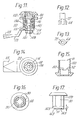
- FIGS. 13 to 27 which represents a sash lock, which is generally provided with the reference number 110, will now be discussed in more detail.
- the closure comprises a tubular housing 120 which, similar to the embodiment shown in FIG. 5, is provided with a sliding surface 52 which has incisions 50.
- the tubular housing 120 has a greater overall length and has at its inner end a projection 111 pointing in the axial direction, which could serve as a stop for a nose 115 carried by the cam tongue 113 in order to limit the rotary movement of the cam lock to essentially 90 °.
- the tube housing 120 has the already with respect to the A described in FIGS. 1 to 10 shown embodiment nfasungen 30 for rotation on, and the attachment is of the tubular body again by means of a screw on a on the outer surface of the tubular housing 120 disposed threaded nut 18.
- the key catch of the tubular housing 120 corresponds to that of the housing 20, with the difference, however, that a total of four radial incisions 176 are provided, each 90 apart.
- the double-bit key can thus be withdrawn from the lock both in the closed position and in the open position, which is advantageous for sash locks because multiple (e.g.
- sash locks are often arranged on a control cabinet door, which expediently all can be opened with only one sash lock key and should be close. During opening, the sash lock must therefore be removable from the first opened lock so that the second or third lock can also be opened without a second or third key now having to be available.
- the actuating shaft 132 is embodied in “two parts” in order to achieve axial displacement of the actuating shaft with respect to the front locking part consisting of sliding surface 52 with incisions 50.
- the construction can also be seen in such a way that the outer part shown in FIG. 19 represents the actuating shaft 132, heard during the in Fig. 21 shown to the inner part sash and tange closure with the lock nut 36 of the S shown in FIG. 1 is comparable.
- the lower part has therefore been given the reference number 136.
- the part 132 essentially corresponds to the part 32 already described in FIG. 9, with only the middle part 54 of the actuating shaft 32 shown in FIG. 9 being significantly shorter because the overall length available here must be smaller.
- the actuating square 26 of the part 132 engages in a corresponding square opening 134 of the part 136, so that there is again a torsionally rigid but axially displaceable connection between the parts 132 and 136.
- the locking spring 40 which is also present here, is received by the part 136 in a corresponding annular groove 142.
- the part 136 has a shoulder surface 143 at its lower end, with which it is supported - possibly with the interposition of a spring washer 112, see FIGS.
- a retaining ring 114 which, after the front part 132, the spring 40, has been inserted and the rear part 136 and possibly the spring ring 112 inserted into the end of the tubular housing 120 and there in a suitable manner.
- the holder 114 also forms the axis of rotation for the shaft part 136, in that its diameter-reduced end 145 comes to fit in the bore 147 of the holder 114.
- Behind the bearing section 145 is a prismatic part 147, in particular a square, on which the sash tongue 113 is plugged with a correspondingly shaped opening 149 and can then be fixed by means of a cap screw 151.
- the screw 151 can be screwed into a threaded bore 153 which is arranged axially in the part 136.
- the mounting end of the sash tongue 113 provided with the opening 149 slides on the retaining ring 114 or the end of the housing 120 and thus represents an axial locking for the part 136, which on the other hand is provided by the shoulder surface 143.
- the retaining ring 114 adjacent an annular groove 155, the k for defining means Eindrük- ung 145 serves, on two ears 157 and an incision 159th
- the ears 157 are arranged in such a way that their surfaces 161 lie against the surfaces 163 of the projection 111 of the housing 120 and, after insertion of the retaining ring 114 into the end of the housing 120, secure it against rotation, on the other hand the ears form with their other surface 165 stop faces for the nose 115 of the sash tongue 113.
- the projection 111 of the housing 120 does not serve directly here, but only via the retaining ring 114 as a stop for the sash tongue 113, although a construction would of course also be possible in which the nose 115 is in direct contact Stops protrusions formed by the housing 120.
- a sealing ring 84 is provided, which can be arranged in an annular groove 82 arranged in part 132.
- the cam lock 110 is assembled during its manufacture in such a way that the inner parts of the housing 120 are plugged together in the manner already described and then the retaining ring 114 is arranged and fixed, whereupon the cam tongue 113 is plugged onto the square 147 projecting from the housing 120 and then the screw 151 is screwed into the threaded bore 153 and - if necessary with the interposition of a locking washer 167 - screwed tight.
- the thread provided for the nut 18 on the outer surface of the housing 120 does not extend all the way to the rear end of the housing, but only to a point which is designated by 169 in FIG. 17.
- the remaining housing length D is slightly larger than the width of the nut 18, so that it is still free on the end of the housing 120 and can be pulled off via the cam tongue 113.
- the tongue 113 does not need to be unscrewed; instead, after removing the nut 18, the sash is inserted through the corresponding punched hole in the door leaf - this is easily possible through the curvature 171 of the tongue 113 - and then the nut 18 Pass over tongue 113 and then screw onto housing 120.
- the lock can be used both as a left-hand lock and as a right-hand lock in that four 90-degree radial incisions 176 are provided, and also in that there are four chamfers 30 offset from one another by 90 °.
- the total housing length of the sash lock shown here is, for example, only 6 mm longer than is the case for prescribers who do not have this additional securing device.
- This additional housing length can be compensated for without difficulty by appropriate dimensioning of the sash tongue 113, which are already available in different dimensions for the different cabinet door constructions.
- the illustrated embodiments relate to double-bit keys, but the invention can equally well be applied to differently shaped keys and associated locks, provided that the precise alignment of the actuating shaft with respect to a key catch in the closed and / or opened state of the lock is important and / or the closure against b eabschreibtes or faulty opening of the door by vibrations t i ons to be backed up, without the possibility of one-hand operation is lost.
Priority Applications (1)
| Application Number | Priority Date | Filing Date | Title |
|---|---|---|---|
| AT81101610T ATE10961T1 (de) | 1980-03-15 | 1981-03-06 | Steckschluesselbetaetigbare arretierungsvorrichtung. |
Applications Claiming Priority (2)
| Application Number | Priority Date | Filing Date | Title |
|---|---|---|---|
| DE3010115 | 1980-03-15 | ||
| DE19803010115 DE3010115A1 (de) | 1980-03-15 | 1980-03-15 | Arretierungsvorrichtung fuer vorreiberverschluesse, stangenverschluesse u.dgl. |
Publications (2)
| Publication Number | Publication Date |
|---|---|
| EP0036141A1 true EP0036141A1 (fr) | 1981-09-23 |
| EP0036141B1 EP0036141B1 (fr) | 1984-12-27 |
Family
ID=6097395
Family Applications (1)
| Application Number | Title | Priority Date | Filing Date |
|---|---|---|---|
| EP81101610A Expired EP0036141B1 (fr) | 1980-03-15 | 1981-03-06 | Dispositif d'arrêt actionné par une clé |
Country Status (3)
| Country | Link |
|---|---|
| EP (1) | EP0036141B1 (fr) |
| AT (1) | ATE10961T1 (fr) |
| DE (2) | DE3010115A1 (fr) |
Cited By (6)
| Publication number | Priority date | Publication date | Assignee | Title |
|---|---|---|---|---|
| EP0175049A2 (fr) * | 1983-05-07 | 1986-03-26 | Dieter Ramsauer | Tourniquet susceptible d'être manoeuvré par une clé à tube |
| EP0175211A1 (fr) * | 1984-09-19 | 1986-03-26 | Dieter Ramsauer | Fermeture de tourniquet actionnée et arrêtée au moyen d'une clé à douille |
| EP0595455A1 (fr) * | 1992-10-28 | 1994-05-04 | Malcoe Precision Fabrications Limited | Serrure |
| WO1999005757A1 (fr) * | 1997-07-22 | 1999-02-04 | Ut Automotive Dearborn, Inc. | Harnais de cables moule dans un coussin en mousse |
| WO2005095740A2 (fr) * | 2004-03-31 | 2005-10-13 | Emka Beschlagteile Gmbh & Co. Kg | Fermeture quart de tour en deux parties |
| DE102022123304A1 (de) | 2022-09-13 | 2024-03-14 | Emka Beschlagteile Gmbh & Co. Kg | Verschluss, insbesondere Vorreiberverschluss |
Families Citing this family (2)
| Publication number | Priority date | Publication date | Assignee | Title |
|---|---|---|---|---|
| DE3908688C2 (de) * | 1989-03-16 | 1997-06-12 | Gruenzweig & Hartmann Montage | Einsteck- oder Kastenschloß für schalldämmende Türen |
| DE9204590U1 (fr) * | 1992-04-03 | 1992-06-11 | Stewing Kunststoffbetrieb Gmbh, 4270 Dorsten, De |
Citations (7)
| Publication number | Priority date | Publication date | Assignee | Title |
|---|---|---|---|---|
| DE246194C (fr) * | ||||
| DE191851C (fr) * | ||||
| DE479565C (de) * | 1927-11-27 | 1929-07-18 | Johan Peter Nielsen | In einer wagerechten Aussparung des Fensterpfostens drehbar angeordneter Drehriegelverschluss |
| CH465432A (de) * | 1966-04-28 | 1968-11-15 | Nakanishi Yoshitaka | Griff-Steckverschluss |
| DE1904922A1 (de) * | 1969-01-31 | 1970-08-20 | Siemens Ag | Kurzschluss-Koaxialschieber fuer Topfkreise |
| DE1955530B2 (de) * | 1969-11-05 | 1973-12-13 | Siemens Ag, 1000 Berlin U. 8000 Muenchen | Verschlußstuck zum Verschließen von Türen oder Abdeckblechen |
| DE7621270U1 (de) * | 1976-07-06 | 1976-12-23 | Fa. Emil Krachten Jun., 5620 Velbert | Stangenverschluss |
Family Cites Families (3)
| Publication number | Priority date | Publication date | Assignee | Title |
|---|---|---|---|---|
| US3661001A (en) * | 1970-08-03 | 1972-05-09 | Keystone Consolidated Ind Inc | Key ejector lock |
| DE7038448U (de) * | 1970-10-17 | 1973-03-29 | Willach H & Soehne Huwil Werke | Moebelschloss |
| US3995463A (en) * | 1975-07-25 | 1976-12-07 | Chicago Lock Co. | Key ejector lock |
-
1980
- 1980-03-15 DE DE19803010115 patent/DE3010115A1/de not_active Ceased
-
1981
- 1981-03-06 DE DE8181101610T patent/DE3167895D1/de not_active Expired
- 1981-03-06 EP EP81101610A patent/EP0036141B1/fr not_active Expired
- 1981-03-06 AT AT81101610T patent/ATE10961T1/de not_active IP Right Cessation
Patent Citations (7)
| Publication number | Priority date | Publication date | Assignee | Title |
|---|---|---|---|---|
| DE246194C (fr) * | ||||
| DE191851C (fr) * | ||||
| DE479565C (de) * | 1927-11-27 | 1929-07-18 | Johan Peter Nielsen | In einer wagerechten Aussparung des Fensterpfostens drehbar angeordneter Drehriegelverschluss |
| CH465432A (de) * | 1966-04-28 | 1968-11-15 | Nakanishi Yoshitaka | Griff-Steckverschluss |
| DE1904922A1 (de) * | 1969-01-31 | 1970-08-20 | Siemens Ag | Kurzschluss-Koaxialschieber fuer Topfkreise |
| DE1955530B2 (de) * | 1969-11-05 | 1973-12-13 | Siemens Ag, 1000 Berlin U. 8000 Muenchen | Verschlußstuck zum Verschließen von Türen oder Abdeckblechen |
| DE7621270U1 (de) * | 1976-07-06 | 1976-12-23 | Fa. Emil Krachten Jun., 5620 Velbert | Stangenverschluss |
Cited By (11)
| Publication number | Priority date | Publication date | Assignee | Title |
|---|---|---|---|---|
| EP0175049A2 (fr) * | 1983-05-07 | 1986-03-26 | Dieter Ramsauer | Tourniquet susceptible d'être manoeuvré par une clé à tube |
| EP0175012A1 (fr) * | 1983-05-07 | 1986-03-26 | Dieter Ramsauer | Verrou rotatif avec moyen d'arrêt, actionné par une clé |
| EP0175049A3 (en) * | 1983-05-07 | 1987-03-25 | Dieter Ramsauer | Socket wrench actuated casement fastener |
| EP0175211A1 (fr) * | 1984-09-19 | 1986-03-26 | Dieter Ramsauer | Fermeture de tourniquet actionnée et arrêtée au moyen d'une clé à douille |
| EP0595455A1 (fr) * | 1992-10-28 | 1994-05-04 | Malcoe Precision Fabrications Limited | Serrure |
| WO1999005757A1 (fr) * | 1997-07-22 | 1999-02-04 | Ut Automotive Dearborn, Inc. | Harnais de cables moule dans un coussin en mousse |
| US6069319A (en) * | 1997-07-22 | 2000-05-30 | Lear Automotive Dearborn, Inc. | Foamed-in harnesses |
| WO2005095740A2 (fr) * | 2004-03-31 | 2005-10-13 | Emka Beschlagteile Gmbh & Co. Kg | Fermeture quart de tour en deux parties |
| WO2005095740A3 (fr) * | 2004-03-31 | 2005-12-29 | Emka Beschlagteile | Fermeture quart de tour en deux parties |
| DE102022123304A1 (de) | 2022-09-13 | 2024-03-14 | Emka Beschlagteile Gmbh & Co. Kg | Verschluss, insbesondere Vorreiberverschluss |
| WO2024056124A1 (fr) * | 2022-09-13 | 2024-03-21 | Emka Beschlagteile Gmbh & Co. Kg | Verrou, en particulier verrou quart de tour |
Also Published As
| Publication number | Publication date |
|---|---|
| DE3167895D1 (en) | 1985-02-07 |
| ATE10961T1 (de) | 1985-01-15 |
| EP0036141B1 (fr) | 1984-12-27 |
| DE3010115A1 (de) | 1981-09-24 |
Similar Documents
| Publication | Publication Date | Title |
|---|---|---|
| EP1290303B1 (fr) | Serrure a barres pour systeme de fermeture | |
| AT513607B1 (de) | Zylinderschloss | |
| EP2868850B1 (fr) | Cadenas | |
| EP0175049B1 (fr) | Tourniquet susceptible d'être manoeuvré par une clé à tube | |
| DE102015001960A1 (de) | Schliesszylinder mit zwei auf gleicher Achse beabstandet zueinander angeordneten Schliessnasen | |
| DE2530116A1 (de) | Notschluesseleinrichtung an einem zylinderschloss mit doppelschliesszylinder | |
| EP0175211B1 (fr) | Fermeture de tourniquet actionnée et arrêtée au moyen d'une clé à douille | |
| EP0036141A1 (fr) | Dispositif d'arrêt actionné par une clé | |
| EP3187671B1 (fr) | Dispositif de verrouillage en tant que sécurité anti-effraction pour par exemple des fenêtres et des portes | |
| EP0713946B1 (fr) | Serrure de meuble ou fermeture | |
| EP2360343B1 (fr) | Fenêtre coulissante ou porte coulissante dotée d'un dispositif de fermeture | |
| DE3204931A1 (de) | Drehbetaetigungshandhabe fuer tueren, fenster oder dergleichen | |
| DE4244414C2 (de) | Verschluß für Fenster, Türen u. dgl. | |
| EP3366873A1 (fr) | Sécurité de fenêtre/porte | |
| EP2752537A2 (fr) | Agencement de ferrure | |
| EP0453626B1 (fr) | Dispositif de fermeture de levier pivotant et enfonçant muni d'une serrure | |
| EP0835975B1 (fr) | Serrure cylindrique | |
| EP1671001B1 (fr) | Serrure | |
| DE3305209C2 (fr) | ||
| EP0495361A1 (fr) | Ferrure pour portes équipées de serrures encastrées à cylindre profilé | |
| EP1116838A1 (fr) | Ferrure de protection pour porte | |
| EP0296337B1 (fr) | Cylindre profilé de fermeture | |
| EP0574594B2 (fr) | Ferrure de porte | |
| EP0861955B1 (fr) | Bouton de fenêtre verrouiable | |
| DE3406975C2 (fr) |
Legal Events
| Date | Code | Title | Description |
|---|---|---|---|
| PUAI | Public reference made under article 153(3) epc to a published international application that has entered the european phase |
Free format text: ORIGINAL CODE: 0009012 |
|
| AK | Designated contracting states |
Designated state(s): AT BE CH DE FR GB IT LU NL SE |
|
| 17P | Request for examination filed |
Effective date: 19820320 |
|
| GRAA | (expected) grant |
Free format text: ORIGINAL CODE: 0009210 |
|
| AK | Designated contracting states |
Designated state(s): AT BE CH DE FR GB IT LI LU NL SE |
|
| PG25 | Lapsed in a contracting state [announced via postgrant information from national office to epo] |
Ref country code: SE Effective date: 19841227 Ref country code: NL Effective date: 19841227 Ref country code: IT Free format text: LAPSE BECAUSE OF FAILURE TO SUBMIT A TRANSLATION OF THE DESCRIPTION OR TO PAY THE FEE WITHIN THE PRESCRIBED TIME-LIMIT;WARNING: LAPSES OF ITALIAN PATENTS WITH EFFECTIVE DATE BEFORE 2007 MAY HAVE OCCURRED AT ANY TIME BEFORE 2007. THE CORRECT EFFECTIVE DATE MAY BE DIFFERENT FROM THE ONE RECORDED. Effective date: 19841227 Ref country code: FR Free format text: THE PATENT HAS BEEN ANNULLED BY A DECISION OF A NATIONAL AUTHORITY Effective date: 19841227 Ref country code: BE Effective date: 19841227 |
|
| REF | Corresponds to: |
Ref document number: 10961 Country of ref document: AT Date of ref document: 19850115 Kind code of ref document: T |
|
| REF | Corresponds to: |
Ref document number: 3167895 Country of ref document: DE Date of ref document: 19850207 |
|
| PG25 | Lapsed in a contracting state [announced via postgrant information from national office to epo] |
Ref country code: AT Effective date: 19850306 |
|
| PG25 | Lapsed in a contracting state [announced via postgrant information from national office to epo] |
Ref country code: LU Free format text: LAPSE BECAUSE OF NON-PAYMENT OF DUE FEES Effective date: 19850331 Ref country code: LI Effective date: 19850331 Ref country code: CH Effective date: 19850331 |
|
| NLV1 | Nl: lapsed or annulled due to failure to fulfill the requirements of art. 29p and 29m of the patents act | ||
| PLBE | No opposition filed within time limit |
Free format text: ORIGINAL CODE: 0009261 |
|
| STAA | Information on the status of an ep patent application or granted ep patent |
Free format text: STATUS: NO OPPOSITION FILED WITHIN TIME LIMIT |
|
| REG | Reference to a national code |
Ref country code: CH Ref legal event code: PL |
|
| EN | Fr: translation not filed | ||
| 26N | No opposition filed | ||
| PGFP | Annual fee paid to national office [announced via postgrant information from national office to epo] |
Ref country code: GB Payment date: 19910301 Year of fee payment: 11 |
|
| PGFP | Annual fee paid to national office [announced via postgrant information from national office to epo] |
Ref country code: DE Payment date: 19910304 Year of fee payment: 11 |
|
| PG25 | Lapsed in a contracting state [announced via postgrant information from national office to epo] |
Ref country code: GB Effective date: 19920306 |
|
| GBPC | Gb: european patent ceased through non-payment of renewal fee | ||
| PG25 | Lapsed in a contracting state [announced via postgrant information from national office to epo] |
Ref country code: DE Effective date: 19921201 |