EP3366873A1 - Sécurité de fenêtre/porte - Google Patents
Sécurité de fenêtre/porte Download PDFInfo
- Publication number
- EP3366873A1 EP3366873A1 EP18158864.1A EP18158864A EP3366873A1 EP 3366873 A1 EP3366873 A1 EP 3366873A1 EP 18158864 A EP18158864 A EP 18158864A EP 3366873 A1 EP3366873 A1 EP 3366873A1
- Authority
- EP
- European Patent Office
- Prior art keywords
- window
- counterpart
- wing
- door lock
- base body
- Prior art date
- Legal status (The legal status is an assumption and is not a legal conclusion. Google has not performed a legal analysis and makes no representation as to the accuracy of the status listed.)
- Granted
Links
- 230000035515 penetration Effects 0.000 claims description 8
- 238000005553 drilling Methods 0.000 claims description 4
- 230000007704 transition Effects 0.000 description 4
- 230000000903 blocking effect Effects 0.000 description 3
- 239000002184 metal Substances 0.000 description 3
- 238000003825 pressing Methods 0.000 description 3
- 230000003993 interaction Effects 0.000 description 2
- 238000005495 investment casting Methods 0.000 description 2
- 239000000463 material Substances 0.000 description 2
- 238000005266 casting Methods 0.000 description 1
- 238000010276 construction Methods 0.000 description 1
- 230000001419 dependent effect Effects 0.000 description 1
- 238000009434 installation Methods 0.000 description 1
- 238000004519 manufacturing process Methods 0.000 description 1
- 238000003860 storage Methods 0.000 description 1
- 238000003466 welding Methods 0.000 description 1
Images


Classifications
-
- E—FIXED CONSTRUCTIONS
- E05—LOCKS; KEYS; WINDOW OR DOOR FITTINGS; SAFES
- E05B—LOCKS; ACCESSORIES THEREFOR; HANDCUFFS
- E05B9/00—Lock casings or latch-mechanism casings ; Fastening locks or fasteners or parts thereof to the wing
- E05B9/08—Fastening locks or fasteners or parts thereof, e.g. the casings of latch-bolt locks or cylinder locks to the wing
- E05B9/082—Fastening locks or fasteners or parts thereof, e.g. the casings of latch-bolt locks or cylinder locks to the wing with concealed screws
-
- E—FIXED CONSTRUCTIONS
- E05—LOCKS; KEYS; WINDOW OR DOOR FITTINGS; SAFES
- E05B—LOCKS; ACCESSORIES THEREFOR; HANDCUFFS
- E05B27/00—Cylinder locks or other locks with tumbler pins or balls that are set by pushing the key in
-
- E—FIXED CONSTRUCTIONS
- E05—LOCKS; KEYS; WINDOW OR DOOR FITTINGS; SAFES
- E05B—LOCKS; ACCESSORIES THEREFOR; HANDCUFFS
- E05B63/00—Locks or fastenings with special structural characteristics
- E05B63/0004—Additional locks added to existing lock arrangements
-
- E—FIXED CONSTRUCTIONS
- E05—LOCKS; KEYS; WINDOW OR DOOR FITTINGS; SAFES
- E05B—LOCKS; ACCESSORIES THEREFOR; HANDCUFFS
- E05B63/00—Locks or fastenings with special structural characteristics
- E05B63/0052—Locks mounted on the "frame" cooperating with means on the "wing"
-
- E—FIXED CONSTRUCTIONS
- E05—LOCKS; KEYS; WINDOW OR DOOR FITTINGS; SAFES
- E05B—LOCKS; ACCESSORIES THEREFOR; HANDCUFFS
- E05B63/00—Locks or fastenings with special structural characteristics
- E05B63/04—Locks or fastenings with special structural characteristics for alternative use on the right-hand or left-hand side of wings
-
- E—FIXED CONSTRUCTIONS
- E05—LOCKS; KEYS; WINDOW OR DOOR FITTINGS; SAFES
- E05B—LOCKS; ACCESSORIES THEREFOR; HANDCUFFS
- E05B63/00—Locks or fastenings with special structural characteristics
- E05B63/12—Locks or fastenings with special structural characteristics with means carried by the bolt for interlocking with the keeper
- E05B63/122—Locks or fastenings with special structural characteristics with means carried by the bolt for interlocking with the keeper with transverse, i.e. vertically movable bolt or dropbolt
-
- E—FIXED CONSTRUCTIONS
- E05—LOCKS; KEYS; WINDOW OR DOOR FITTINGS; SAFES
- E05B—LOCKS; ACCESSORIES THEREFOR; HANDCUFFS
- E05B65/00—Locks or fastenings for special use
- E05B65/06—Locks or fastenings for special use for swing doors or windows, i.e. opening inwards and outwards
-
- E—FIXED CONSTRUCTIONS
- E05—LOCKS; KEYS; WINDOW OR DOOR FITTINGS; SAFES
- E05B—LOCKS; ACCESSORIES THEREFOR; HANDCUFFS
- E05B9/00—Lock casings or latch-mechanism casings ; Fastening locks or fasteners or parts thereof to the wing
- E05B9/08—Fastening locks or fasteners or parts thereof, e.g. the casings of latch-bolt locks or cylinder locks to the wing
-
- E—FIXED CONSTRUCTIONS
- E05—LOCKS; KEYS; WINDOW OR DOOR FITTINGS; SAFES
- E05C—BOLTS OR FASTENING DEVICES FOR WINGS, SPECIALLY FOR DOORS OR WINDOWS
- E05C1/00—Fastening devices with bolts moving rectilinearly
- E05C1/004—Fastening devices with bolts moving rectilinearly parallel to the surface on which the fastener is mounted
- E05C1/006—Fastening devices with bolts moving rectilinearly parallel to the surface on which the fastener is mounted parallel to the wing edge
-
- E—FIXED CONSTRUCTIONS
- E05—LOCKS; KEYS; WINDOW OR DOOR FITTINGS; SAFES
- E05C—BOLTS OR FASTENING DEVICES FOR WINGS, SPECIALLY FOR DOORS OR WINDOWS
- E05C1/00—Fastening devices with bolts moving rectilinearly
- E05C1/02—Fastening devices with bolts moving rectilinearly without latching action
-
- E—FIXED CONSTRUCTIONS
- E05—LOCKS; KEYS; WINDOW OR DOOR FITTINGS; SAFES
- E05C—BOLTS OR FASTENING DEVICES FOR WINGS, SPECIALLY FOR DOORS OR WINDOWS
- E05C1/00—Fastening devices with bolts moving rectilinearly
- E05C1/02—Fastening devices with bolts moving rectilinearly without latching action
- E05C1/04—Fastening devices with bolts moving rectilinearly without latching action with operating handle or equivalent member rigid with the bolt
Definitions
- the present invention relates to a window / door lock for securing a, in particular outwardly opening, wing of a window or a door in a closed position, in which the wing rests against a frame of the window or the door.
- a window / door lock for securing a, in particular outwardly opening, wing of a window or a door in a closed position, in which the wing rests against a frame of the window or the door.
- a window / door security for example, comprise a base body and a counterpart, which is optionally lockable on the base body.
- a counterpart which is optionally lockable on the base body.
- attaching the body to the frame and the counterpart to the wing can then be secured by locking the counterpart to the body of the wing in the closed position. It is advantageous to provide the usually heavier and more voluminous body on the frame and the generally more compact counterpart on the wing.
- the window / door lock is expediently mounted on an inner side of the window or the door, so that it is not directly accessible from the outside during a break-in attempt.
- windows and doors that open to the inside there is usually enough space for attaching the window / door lock on the wing and the frame of the window or door available.
- Will the wings, however open to the outside, as it is widespread for windows in Scandinavia the usable on the inside of the frame and in particular of the wing for attachment of the window / door security area is usually very limited. This is because, in the closed position, the sash bears against the stationary frame from the outside, so that a large part of the sash frame is concealed by the frame on the inside and is therefore not available for securing the window / door lock.
- the main body of the window / door security can be specially designed for attachment to the frame, in particular have a mounting surface which is substantially flat in order to be able to be applied flat to a corresponding surface of the frame can.
- the mounting surface may be adapted for cooperation with fasteners, such as fasteners. Screws, be formed, by means of which the base body can be attached to the frame.
- fasteners such as fasteners.
- Screws be formed, by means of which the base body can be attached to the frame.
- the possibilities of positioning and aligning the base body with the frame may be limited.
- an actuator may be provided on the body.
- the actuator is then conveniently located at a location that is easily accessible in a predetermined position and orientation for a person standing in front of the window or the door person in the arrangement of the body.
- an ideal position of the actuating element may depend, for example, on whether the respective wing opens on the left (ie the hinges are on the right) or on the right (the hinges are therefore on the left).
- the window / door lock is designed for an arrangement on a left-opening wing, this window / door lock may not be attached to a right-opening wing or the actuator is then located in a difficult to reach place.
- the basic body of the window / door lock has two mounting surfaces, so that the basic body can be optionally applied and fixed to the frame with one of the mounting surfaces, wherein the two mounting surfaces are aligned perpendicular to one another.
- two mounting surfaces are provided on the base body, which can optionally be used for fastening the base body to the frame of the window or the door and which extend at least substantially along a respective plane of extent, these two extension planes at an angle of 90 ° aligned with each other.
- it can be selected for the assembly of the body on the frame, with which of the two mounting surfaces of the body is to be attached thereto.
- the mutually perpendicular alignment of the two mounting surfaces makes it possible that the window / door lock to be mounted at an angle between the frame and the wing, then with a closed wing a mounting surface on the frame and the other mounting surface rests on the wing, so that not for the attachment the base body used mounting surface for interaction with the counterpart can be used.
- the angled orientation of the mounting surfaces also allows flexible positioning of the window / door lock on a left-opening wing as well as on a right-opening wing, since by appropriate choice of the mounting surface used for mounting an orientation of the body regardless of whether the window / Door safety is attached to the left or right, can be maintained substantially, so that an optionally provided on the main body actuator can be accessible in both cases from the same direction.
- the direction from which the actuator is to be actuated can be changed so that e.g. can be freely selected in a left-mounted window / door lock, whether the actuator should be actuated from above or from below.
- the window / door lock can be mounted not only on vertical sides of a window or a door, but also on horizontal sides.
- the two mutually perpendicular mounting surfaces adjacent to each other whereby the window / door security be made particularly compact and can be fitted well between the wing and frame.
- the window / door security can be arranged in such an angle between the frame and the wing, that the one mounting surface to the frame and the other mounting surface to the wing and the edge between the mounting surfaces sits deeply at an angle.
- the window / door lock has an elongated shape along a longitudinal axis parallel to both mounting surfaces, wherein the mounting surfaces then preferably have a greater extent in the direction of the longitudinal axis than transversely thereto.
- the extension in the direction of the longitudinal axis is at least twice as large, preferably at least three times as large as the extension transverse to the longitudinal axis.
- Such a window / door security can then be mounted in particularly narrow angles between the frame and the casement, as they are present especially in outward-opening wings.
- the two mounting surfaces each have at least one screw feedthrough, preferably at least two screw feedthroughs, through which a screw can be guided in each case for fastening the basic body to the frame.
- the base body can be screwed through one of the mounting surfaces to the frame. If this is done with at least two screws, the attachment is also secure against rotation.
- the base body is designed to be used as a drilling template for the attachment of the counterpart on the wing, while the base body is attached to the frame.
- the base body is designed so that it can serve as a drilling template for drilling the mounting holes for the counterpart by stopping at frame and wings.
- the counterpart can have one or more screw feedthroughs through which a screw can be guided for fastening the counterpart to the wing, the arrangement of the screw feedthroughs of the counterpart corresponding to the arrangement of the screw penetrations of a respective mounting surface of the base body.
- the attachment of the window / door security can then be carried out as follows, for example.
- the base body is applied at a suitable location with one of its mounting surfaces to the frame, the other mounting surface facing the wing.
- Through the screw through the voltage applied to the frame mounting surface through holes for the screws can then be drilled in the frame or the screws are screwed directly into the frame.
- the screw-throughs of the others, to Wing-facing mounting surface of the body are then just arranged so that holes drilled through them for the counterpart to the wing screws screwed into the wing or at least the corresponding positions can be marked.
- the counterpart can be accurately positioned in this way using the body in a simple manner.
- the base body has a receptacle, that is to say a receiving space, for receiving a locking portion of the counterpart.
- the base body and the counterpart are expediently fastened to the frame or the wing such that in the closed position of the wing, the locking portion of the counterpart is received in the receptacle of the base body.
- a bolt may be provided on the base body, which engages behind the latch portion, for example, as will be explained below.
- the body has a single, common receptacle for receiving the locking portion of the counterpart.
- the two mounting surfaces each have a receiving opening, through which the locking portion can penetrate into the receptacle.
- a respective mounting surface may thus alternatively be used to secure the base body to the frame, and secondly to lock the counterpart in the base body by providing the mounting surface with a receiving opening through which the locking portion of the counterpart into the receptacle can reach where it can then be locked.
- the other When one mounting surface is used for attachment, the other is available for co-operation with the counterpart, and vice versa.
- the receiving opening of the other of the two mounting surfaces can be exposed, so that the locking portion of the counterpart through this exposed receiving opening in the receptacle of the body can penetrate.
- the receiving opening in particular in the middle, is arranged between two screw feedthroughs of the respective mounting surface.
- the screw penetrations and the receiving opening can be distributed along a longitudinal axis of the window / door security, wherein the receiving opening is located between two SS be exchangeen.
- the window / door lock is designed to be particularly stable in such an embodiment. For then there is the receptacle for receiving the locking portion of the counterpart in a region between two screw penetrations over which the body is attached to the frame.
- the two mounting surfaces in particular with respect to the position of respective screw penetrations and / or receiving openings, are symmetrical to each other. Because such a symmetry contributes to the fact that it makes no functional difference, which of the mounting surfaces for the attachment of the body to the frame and which is selected for interaction with the counterpart. Since therefore neither of the two options is preferred over the other, the window / door security can be mounted in a particularly flexible manner substantially only with regard to a desired position and orientation on the window or on the door.
- the two mounting surfaces may be formed symmetrically with respect to each other in particular with respect to a plane which extends at a 45 ° angle to each of the two mounting surfaces.
- the window / door lock comprises a latch movably mounted on the base body between a release position and a locking position, by means of which the counterpart can be locked to the base body.
- the locking of the counterpart on the base body can be effected in particular by the fact that in the closed position of the wing, a locking portion of the counterpart is received in a formed on the body recording and that the bolt in the locking position blocks the locking portion of the counterpart in the receptacle, preferably a positive fit blocked, for example, by engaging behind the latch portion.
- the receptacle referred to here and the locking section mentioned here may in particular correspond to the receptacle described above or the latch section described above.
- the bolt Due to the fact that the blocking of the locking portion by the bolt takes place within a receptacle for the locking portion in the base body, the bolt can be particularly well supported and the locking portion can be particularly well protected against dodging from a blocking engagement or rear grip, resulting in the reliability of Lock contributes.
- the bolt is aligned parallel to the two mounting surfaces and / or movable.
- the latch is formed as an elongate bolt, which is aligned with its longitudinal extent parallel to the mounting surfaces and movable.
- the bolt can be mounted to be movable in a straight line.
- Such a bar can be particularly well integrated into a correspondingly elongated window / door security, so that they can be made compact overall.
- the inclusion of the locking portion of the counterpart in the receptacle of the body takes place in particular by a receiving opening formed in the respective mounting surface and thus at least substantially perpendicular to the respective mounting surface.
- the parallel to the mounting surface movable latch blocks in particular engages behind the latch portion of the counterpart therefore perpendicular to the direction of movement, which additionally contributes to the reliability of the lock.
- the bolt is arranged in the locking position such that it is blocked by screw through the mounting surfaces guided screws with which the body is attached to the frame against loosening.
- the bolt may be arranged on the base body in such a way that the bolt in the locking position covers at least one screw leadthrough of the respective mounting surface. This can result, in particular, in that the axes of the screw feedthroughs oriented perpendicular to the respective mounting surface, along which screws are guided along the screw leadthrough, intersect the bolt located in the locking position. If the latch is arranged close enough to the mounting surfaces, in particular at a distance which is less than the length of the screws used, the screws are therefore blocked by the bolt against removal from the respective screw leadthrough.
- the bolt locks in the locked position not only the counterpart to the body, but also secures the mounted window / door lock against unauthorized loosening.
- the window / door lock comprises a locking mechanism, which is arranged on the base body and adapted to selectively lock the bolt in the locking position against moving into the release position.
- a locking mechanism can secure the latch against unauthorized operation by locking the latch in the latching position and releasing it for movement to the release position only when the latching mechanism is released.
- the locking mechanism can be solved only by someone and the bolt thus be released, which has a certain secret of secrecy, which may be, for example, a numeric code or a key.
- yet another locking position may be defined, which can take the latch stable, but without being locked by the locking mechanism can.
- the further locking position of the locking portion of the counterpart is prevented as well as in said locking position at a leaving the recording of the body by the bolt, so that even in the further locking position, the counterpart is secured to the body.
- advantageously in the further locking position be used to fasten the base body screws blocked by the bolt against loosening.
- the functional difference between said and the further locking position is essentially the fact that only the said locking position, but not also the further locking position for improved security is additionally lockable by the locking mechanism.
- the further locking position is preferably between the release position and said lockable locking position of the bolt. In this way, it can be selected depending on the need for security, whether the bolt is released from the release position either only in the further locking position to lock the counterpart to the body, this lock can be solved comfortably without locking secret again, or beyond the lockable locking position is displaced to additionally secure the lock by the locking mechanism against unauthorized loosening.
- the locking of the bolt in the lockable locking position is preferably carried out automatically with reaching the lockable locking position, which can be achieved, for example, characterized in that the locking mechanism is biased in a locking the locking state.
- the locking mechanism comprises a lock cylinder
- the cylinder axis is aligned at an angle of 45 ° to the two mounting surfaces.
- the cylinder axis may in particular correspond to a rotation axis of a rotatable cylinder core of the lock cylinder.
- the lock cylinder can be actuated by means of an associated key to release the lock of the bolt.
- the foundedraum is then aligned parallel to the cylinder axis of the lock cylinder and thus also at an angle of 45 ° to the two mounting surfaces. If the window / door lock was mounted at an angle between the frame and the wing, so is the lock cylinder or the key in the direction bisector of the window / door security. As a result, the key is easily accessible even in tight spaces, making the operation of the window / door security is simplified.
- the lock cylinder is a lock cylinder with Scheibenzuticaen.
- a lock cylinder of this type allows (compared to, for example, a lock cylinder with pin tumblers) only a limited angle of rotation. However, a limited angle of rotation may be sufficient to lock the said latch in the locked position and at the same time provide better protection against so-called picking.
- such a lock cylinder allows for a variety of different locks (i.e., different lock secrets that the lock cylinder can be encoded) in, especially with respect to the cylinder axis extension, of a comparatively compact design.
- the window / door lock on an actuating mechanism via which the bolt is displaceable in the manner of the face of a ballpoint pen.
- the latch can then be biased for example in the direction of the release position and be displaced by pressing an actuating pin from the release position in the direction of the locking position and slightly beyond. When so far displaced, it activates a limit stop which blocks biased return of the latch to the release position thereby holding the latch in the locked position. If the bolt is then again offset by pressing the actuating pin out of the locking position beyond this, the limit stop is thereby deactivated again, so that the bolt is then returned by the bias back to the release position.
- Such a mechanism allows a particularly intuitive and comfortable operation of the bolt.
- at the position of the actuating pin directly read the locking state of the bolt.
- the actuating mechanism can be clipped onto the base body.
- locking means may be provided which engage when the actuating mechanism is pressed against the base body.
- an outer cover of the window / door lock separately from the actuating mechanism or be clipped together with this on the body.
- the base body generally has a hard metal as the material.
- the actuating mechanism and / or the outer cover may, on the other hand, comprise a plastic material.
- the counterpart has a cooperating with the base body for locking the counterpart on the base body locking portion which is formed as an eyelet.
- a bolt provided on the base body, such an eyelet can then be engaged behind the main body in particular simply by locking the counterpart, so that the bolt is guided through the eyelet.
- a design of the locking portion as eyelet is structurally comparatively simple, but at the same time allows a stable locking.
- the counterpart has a T-shape with a shank and a transverse strut, wherein the shank of the T-shape or a part of the shank forms a locking section cooperating with the main body for locking the counterpart on the main body, and wherein the transverse strut of the T Form has a contact surface for attachment of the counterpart on the wing.
- a counterpart can be made particularly compact, for example by the shaft and the transverse strut of the T-shape are each formed as flat sections.
- the shaft can be designed as an eyelet as generally described above for a locking portion of the counterpart, or can have an eye, so that it can cooperate with a bolt on the base body.
- the contact surface preferably has one or more screw feedthroughs, in particular on both legs of the transverse strut, in each case one screw feedthrough, so that the counterpart can be fastened to the wing by means of screws guided through the screw feedthroughs. Since the function of the counterpart can be limited to be fixed to the wing and provide a locking portion for locking to the base body, the counterpart can be made very compact, so that the stem and the cross member of the T-shape are very short ,
- the counterpart may be formed, for example, as a one-piece investment casting.
- the counterpart may also include a baseplate, e.g. a sheet metal, which form the contact surface of the counterpart or the cross member of the T-shape and with a (at least initially) separate component, such as a short piece of pipe, which then forms the latch portion or the stem of the T-shape, e.g. can be connected by welding, screwing, riveting or nesting.
- the counterpart is at least in two parts and comprises two, preferably identical, angle elements, in particular angle plates, each with two perpendicularly aligned legs, wherein the angle elements are each partially cut at the edge at which the two respective legs meet, so that the angle elements can be inserted into one another such that the two angle elements together have a T-shape, one leg of the one angle element and a leg of the other angle element abut each other and form the shaft of the T-shape and the other two legs, the two legs forming the cross brace of the T-shape.
- Such a counterpart can be particularly simple and inexpensive to manufacture, especially if the two angle elements are of identical construction, but has a comparatively high stability and flexural rigidity under tensile load, since the two angle elements hooked under train into each other.
- the window / door lock for attachment of the counterpart on the wing comprises a fastening means, which is a base portion, at least one extending away from the base portion, in particular pin-shaped, extension, which is preferably designed in the manner of a threaded sleeve or a screw shaft and an anti-rotation device, wherein the attachment means is adapted to be disposed with the base portion on one side of the wing and to extend with the extension so far into the wing or through the wing that the counterpart on the opposite side the wing can be connected to the extension, and thereby secured by the rotation against rotation.
- the mentioned sides of the wing are in particular the inside and the outside of the wing.
- the base portion is preferably arranged on the outside of the wing, so that the counterpart can be attached to the inside of the wing.
- the fastening means can rotate in the mounted state to said extension.
- This is particularly important in an embodiment of the extension as a threaded sleeve, a screw shaft or other element with internal or external thread, which is connected by screwing with the counterpart, important so that this screw can not be released from the side of the base portion.
- the anti-rotation is formed as at least one further extending from the base portion away, in particular pin-shaped, extension which also extends into the wing inside. Such an extension is thus not accessible from the side of the base portion, but locks a rotation of the fastener to the other extension.
- the further extension can only serve to prevent rotation and, for this purpose, in principle quite different, in particular also substantially shorter, than the other extension serving for connection to the counterpart.
- the further extension can only be formed by a short tooth-shaped projection.
- the other extension may alternatively be formed very similar to the other extension and also extend so far into the wing or through the wing, that the counterpart can also be connected to the other extension.
- the further extension may also have a thread and in particular be designed in the manner of a threaded sleeve or a screw shaft.
- the invention also relates to a window / door lock for securing a, in particular outwardly opening, wing of a window or a door in a closed position, in which the wing to regardless of the design of the body, in particular independent of the arrangement of respective mounting surfaces of the body rests against a frame of the window or the door, wherein the window / door fuse comprises a base body and a counterpart, which is selectively lockable to the body, so that when attaching the body to the wing and the counterpart to the frame or vice versa of the body the frame and the counterpart can be secured to the wing by locking the counterpart to the main body of the wings in the closed position, wherein the counterpart two, preferably identical, angle elements, in particular angle plates, each with two at an angle of 90 ° to each other aligned legs holds, wherein the angle elements are each partially cut at the edge at which the two respective legs meet, so that the angle elements can be inserted into one another such that the two angle elements together have a T-shape, wherein one leg of the
- the invention also relates regardless of the design of the body, in particular regardless of the arrangement of respective mounting surfaces of the body, a window / door lock for securing a, in particular outwardly opening, wing of a window or a door in a closed position, in which the wing rests against a frame of the window or the door
- the window / door fuse comprises a base body and a counterpart which is selectively lockable to the base body, so that when fixing the base body to the wing and the counterpart to the frame or vice versa of the base body can be secured to the frame and the counterpart on the wing by locking the counterpart to the body of the wings in the closed position
- the window / door lock for fixing the counterpart or the base body to the wing comprises a fastening means
- the base portion, aindee st is an extending away from the base portion, in particular pin-shaped, extension, which is preferably designed in the manner of a threaded sleeve or a screw shaft, and a rotation, wherein
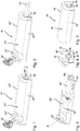
- a window / door lock 11 each have an elongated shape which extends along a longitudinal axis L and which at the two end faces 13 of its longitudinal extension and at the two in the Fig. 1 and 2 visible side surfaces 15, 15 'is limited by a cover 17 to the outside. While the transition between the two covered by the cover 17 side surfaces 15, 15 'is rounded, the transitions to the two other side surfaces 19, 19', in the Fig. 1 and 2 are not visible, as well as the transition between these two side surfaces 19, 19 'formed as a right-angled edges. These uncovered side surfaces form mounting surfaces 19, 19 'of the window / door lock 11 and are perpendicular to each other and to the respectively adjacent further side surface 15 or 15' aligned (see also the shape of the end face 13 and Fig. 4 ).
- a cylindrical projection 21 in the cover 17, which is aligned at an angle of 45 ° to the two mounting surfaces 19, 19' and a lock cylinder 23 accommodates (see. Fig. 3 in which the window / door lock 11 is shown without the cover 17).
- the lock cylinder 23 is aligned such that its cylinder axis Z is an angle bisector of the angle between the two mounting surfaces 19, 19 '(see also the sectional view of Fig. 8 in whose sectional plane the longitudinal axis L and the cylinder axis Z lie).
- an actuating element 33 is provided on the window / door lock 11, which is part of an actuating mechanism 35 (cf. Fig. 8 ), by means of which a latch 37 between a locking position and a release position can be moved.
- the actuating mechanism 35 is formed in the embodiment shown in the manner of a pressure ballpoint pen mechanism, so that the latch 37 can be displaced by pressing the pin-shaped actuating element 33, which extends through an opening in the end face 13, like the expression of a pressure ballpoint pen (cf. Fig. 1 and 2 ).
- Fig. 3 is the embodiment of Fig. 1 and 2 without the cover 17 and without inserted key 25 shown.
- Essential element of the window / door lock 11 is the base body 39, which is designed to be particularly stable and made of metal, for example as a casting, while the cover and the actuating mechanism are preferably at least substantially made of plastic.
- the base body 39 is shaped so that the lock cylinder 23 can be inserted perpendicular to the longitudinal axis L and the latch 37 is movably mounted along the longitudinal axis L in the base body 39.
- the actuating mechanism 35 is clipped to a web 41 of the main body 39.
- the cover 17 can be easily placed on the base body 39 latching.
- the window / door lock 11 can be assembled comparatively easily, wherein the main body 39 is the essential supporting structure of the window / door lock 11.
- the mounting surfaces 19, 19 ' are also defined, as with respect to the Fig. 6 to 8 will be explained in more detail.
- Fig. 1 and 2 two different positions of the actuating element 33 are shown.
- position in which the actuator 33 terminates flush with the end face 13 corresponds to a locking position of the bolt 37, in which this engages a trained as an eye 43 locking portion 45 of a counterpart 47 which extends into a receptacle 49 within the body 39 of the window / door 11, when the to be secured wing 27 is closed (see also Fig. 6 to 8 ).
- the counterpart 47 is locked to the base body 39 by the latch 37 in the locking position, whereby then the wing 27 is secured in its closed position.
- Fig. 1 shown position in which the actuator 33 terminates flush with the end face 13 corresponds to a locking position of the bolt 37, in which this engages a trained as an eye 43 locking portion 45 of a counterpart 47 which extends into a receptacle 49 within the body 39 of the window / door 11, when the to be secured wing 27 is closed (see also Fig. 6 to 8 ).
- the counterpart 47 is locked to the base body
- a further locking position may be provided, in which the actuating element 33 projects only slightly beyond the end face 13. Also in this further locking position of the latch 37 projects through the eyelet 43, so that the counterpart 47 is locked to the base body 39 and the wing 27 is thus secured in the closed position.
- the actuating mechanism 35 can then be effective between the release position and this further locking position in the manner of a ballpoint pen, wherein the in Fig. 1 Locking position shown is then achieved in that the actuating element 33 is pushed beyond the further locking position also completely in the end face 13. In this position, the latch 37 is then held in cooperation with the lock cylinder 23, from which it is locked against leaving the locking position.
- an annular groove of the bolt 37 is engaged behind by a cooperating with the lock cylinder 23 locking element, as in the sectional view of Fig. 8 is shown. From the the Fig. 1 corresponding locking position, the latch 37 can therefore only reach the release position when the lock cylinder 23 is actuated by the associated key 25. Through this lockable locking position Thus, the window / door lock 11 is additionally secured against unauthorized unlocking.
- the Fig. 5 shows an alternative embodiment of the window / door lock 11, which has no lock cylinder 23.
- the adjustment of the bolt 37 takes place exclusively by actuation of the actuating element 33.
- Another locking position is not provided in this embodiment. Rather, the latch 37 can only by the actuating mechanism 35 between two defined position, namely a release position and a (not additionally lockable) locking position, the in Fig. 5 shown position, be adjusted.
- a wing 27 can be reliably secured in its closed position by means of such not additionally lockable window / door lock 11.
- the in the Fig. 1 to 4 shown embodiment of the window / door lock 11 is in the Fig. 6 to 8 shown from further angles, so that in particular the mounting surfaces 19, 19 'can be seen.
- the mounting surfaces 19, 19 ' are primarily defined by corresponding surfaces of the base body 39. Since the cover 17 also covers the actuating mechanism 35 as an extension of the base body 39, the area enlarged by this extension can be regarded as the respective mounting surface 19, 19 ', so that the base body 39 and cover 17 jointly define the mounting surfaces 19, 19'.
- the two mounting surfaces 19, 19 ' are formed at least substantially flat, in order to rest on the wing 27 and the frame 29 of a window 31 and a door.
- two screw feedthroughs 51 are formed in the two mounting surfaces 19, 19 'on the main body 39, so that the main body 39 and the elements connected thereto via one of the mounting surfaces 19, 19 'can be screwed to the frame 29.
- the counterpart 47 is attached to the wing 27.
- a receiving opening 53 is provided, through which the latch portion 45 of the counterpart 47 can reach into the receptacle 49 formed centrally in the base body 39.
- both mounting surfaces 19, 19 ' are equally suitable for attachment of the body 39 via through the screw holes 51 guided through screws and for receiving the locking portion 45 of the counterpart 47 through the receiving opening 53 in the receptacle 49 Fig. 6 the counterpart 47 not only as in Fig.
- FIG. 7 represented at one point, from where it can cooperate with the base body 39 via the lower mounting surface 19 ', but additionally (dashed) also at a further point from which it can interact with the base body 39 just as reliably via the front mounting surface 19 ,
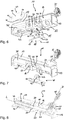
- Fig. 9 illustrated in the four window / door fuses 11 are arranged on an outwardly opening double-winged window 31 in order to secure the two in their respective closed position on the frame 29 wings 27 against opening can.
- the 6 and 7 show a possible embodiment of the counterpart 47, in which the counterpart 47 has a T-shape, on the shank of the locking portion 45 is formed with the eyelet 43 and the transverse strut forms a contact surface 55 with two ring be exchangeen 51.
- the counterpart 47 can be reliably screwed to the contact surface 55 on the wing 27, have a protruding and stably fixed latch portion 45 and at the same time be made very compact.
- the counterpart 47 is formed as a one-piece precision casting.
- An alternative embodiment is in Fig. 10 shown.
- the basic structure of in Fig. 10 shown embodiment of the counterpart 47 corresponds to that of the in the 6 and 7 shown embodiment.
- the counterpart 47 has a T-shape with latch portion 45 and contact surface 55.
- the counterpart 47 is formed in two parts and comprises two identical rectangular angle elements 57. At the edge on which the legs of a respective angle element 57 adjoin one another, the angle elements 57 are each cut to the middle, so that the angle elements 57 can be inserted into each other as shown and the counterpart 47 thus formed then has a T-shape.
- the shaft of the T-shape is formed by two abutting legs, which are part of a respective other angle member 57.
- the counterpart 47 can be easily screwed into the sash of the wing 27.
- a more stable attachment results, however, if an additional fastening means 59 is provided which extends through the sash extends through.
- a possible embodiment of such a fastening means 59 is shown in FIG Fig. 11 shown.
- the fastening means has a base portion 61, from which extends a pin-shaped extension 63 which is formed as a threaded sleeve with internal thread.
- the fastening means 59 can then be guided with the extension 63 through the wing frame of the wing 27 to attach the counterpart 47 by means of a screw which is screwed into the extension 63.
- the extension does not have to extend completely through the casement.
- the fastening means 59 can also have further corresponding projections 63, in particular also designed as a threaded sleeve. Since then several extensions 63 extend through the casement, the fastening means 59 is thereby secured against rotation, so that the screw from the wing side, on which the base portion 61 rests, can not be screwed.
- an anti-rotation 65 may be formed in the form of another pin-shaped extension to the base portion 61. This further extension 65 then does not need to have threads and can be significantly shorter than the extension 63 cooperating with the counterpart 47. For it is sufficient that the further extension 65 engages in the sash to act as anti-rotation 65 for the fastener 59.
Applications Claiming Priority (1)
| Application Number | Priority Date | Filing Date | Title |
|---|---|---|---|
| DE102017104102.8A DE102017104102A1 (de) | 2017-02-28 | 2017-02-28 | Fenster-/Türsicherung |
Publications (2)
| Publication Number | Publication Date |
|---|---|
| EP3366873A1 true EP3366873A1 (fr) | 2018-08-29 |
| EP3366873B1 EP3366873B1 (fr) | 2020-04-08 |
Family
ID=61521331
Family Applications (1)
| Application Number | Title | Priority Date | Filing Date |
|---|---|---|---|
| EP18158864.1A Active EP3366873B1 (fr) | 2017-02-28 | 2018-02-27 | Sécurité de fenêtre/porte |
Country Status (4)
| Country | Link |
|---|---|
| US (1) | US10480212B2 (fr) |
| EP (1) | EP3366873B1 (fr) |
| DE (1) | DE102017104102A1 (fr) |
| DK (1) | DK3366873T3 (fr) |
Cited By (1)
| Publication number | Priority date | Publication date | Assignee | Title |
|---|---|---|---|---|
| US10801233B2 (en) | 2018-04-03 | 2020-10-13 | Knox Associates, Inc. | Fluid guard and absorber for locking devices |
Families Citing this family (1)
| Publication number | Priority date | Publication date | Assignee | Title |
|---|---|---|---|---|
| US20180119455A1 (en) * | 2016-11-02 | 2018-05-03 | Joshua J. Miller | Latch style lock that secures rolling cargo door |
Citations (6)
| Publication number | Priority date | Publication date | Assignee | Title |
|---|---|---|---|---|
| US1812988A (en) * | 1928-03-29 | 1931-07-07 | Segal Samuel | Lock |
| DE8804633U1 (fr) * | 1988-04-08 | 1988-07-21 | Sondermann, Horst, 5620 Velbert, De | |
| US6684669B1 (en) * | 1997-02-19 | 2004-02-03 | Joseph Talpe | Door fastener device |
| DE102006047708A1 (de) * | 2006-10-09 | 2008-04-10 | ABUS August Bremicker Söhne KG | Fenster-/Türsicherung |
| WO2015077827A1 (fr) * | 2013-11-27 | 2015-06-04 | Meredith Dale Herbert | Dispositif de retenue de châssis de fenêtre |
| EP2933410A1 (fr) * | 2014-04-15 | 2015-10-21 | GEZE GmbH | Entraînement de porte |
Family Cites Families (30)
| Publication number | Priority date | Publication date | Assignee | Title |
|---|---|---|---|---|
| US796280A (en) * | 1905-02-28 | 1905-08-01 | William C Applegate | Sash-lock. |
| US1381395A (en) * | 1920-09-03 | 1921-06-14 | Yale & Towne Mfg Co | Lock |
| US1398636A (en) * | 1921-01-25 | 1921-11-29 | Forlander Morris | Lock |
| US1512939A (en) * | 1923-09-04 | 1924-10-28 | Yale & Towne Mfg Co | Lock |
| US1584950A (en) * | 1924-10-18 | 1926-05-18 | Clive W Lanphere | Curved bolt lock |
| US1966171A (en) * | 1925-03-12 | 1934-07-10 | Holtzman John | Hand operated lock |
| US2605517A (en) * | 1949-09-02 | 1952-08-05 | J W Rucker | Window lock and grill |
| US2730970A (en) * | 1952-12-01 | 1956-01-17 | Frank V Martin | Protective device for door locks |
| DE1708009U (de) | 1955-07-26 | 1955-10-06 | Ansehn Schmuck Wuensch | Filter aus schaumstoff. |
| US3078704A (en) * | 1959-06-24 | 1963-02-26 | Rifkin Michael | Window latching device |
| US3082617A (en) * | 1961-10-02 | 1963-03-26 | Kerman Nathan | Window lock |
| US3312794A (en) * | 1963-11-15 | 1967-04-04 | Heinemann Electric Co | Circuit breaker handle with transversely slidable restraining means |
| FI41351B (fr) | 1967-06-06 | 1969-06-30 | Niilola Armas K | |
| US3460861A (en) * | 1967-08-30 | 1969-08-12 | Niilola Armas K | Staples for padlock |
| US3580017A (en) * | 1969-11-05 | 1971-05-25 | Ideal Security Hardware Co | Lock with means concealing mounting fasteners |
| US3858923A (en) * | 1973-10-18 | 1975-01-07 | Frank C Bunn | High security hasp |
| US4138150A (en) * | 1975-10-01 | 1979-02-06 | Bills Marius W | Window lock |
| NZ217287A (en) * | 1985-08-22 | 1988-08-30 | Ogden Industries Pty Ltd | Security bolt |
| GB2282842A (en) * | 1993-10-13 | 1995-04-19 | Shieh Jin Ren | Adjustable door bolt. |
| GB2301141A (en) | 1995-05-22 | 1996-11-27 | Epwin Group Plc | Locking device |
| US6688656B1 (en) * | 1999-11-22 | 2004-02-10 | Truth Hardware Corporation | Multi-point lock |
| GB0005755D0 (en) * | 2000-03-11 | 2000-05-03 | Banham Patent Locks Ltd | Lock |
| DE10101767B4 (de) | 2001-01-16 | 2018-02-01 | ABUS August Bremicker Söhne KG | Zusatzband als Bandsicherung für einen Dreh-Kipp-Flügel |
| TW501633U (en) * | 2001-12-21 | 2002-09-01 | Chuen-Yi Liu | Door lock with double locking hooks |
| US7261342B2 (en) * | 2003-04-08 | 2007-08-28 | Smith Richard B | Automatically locking window latch |
| US6981724B2 (en) * | 2003-05-13 | 2006-01-03 | Fasco Die Cast, Inc. | Multi-point lock assembly |
| US7640772B2 (en) * | 2006-05-24 | 2010-01-05 | James Johnson | Watersports apparatus locking device |
| GB2441453B (en) | 2007-11-06 | 2008-08-27 | David Paul Naill Abbott | Locks for windows and doors |
| US8646815B2 (en) * | 2008-11-18 | 2014-02-11 | Nationwide Industries, Inc. | Gate latch |
| DK201200500A (en) | 2012-08-10 | 2014-02-11 | Lindrucker Aps | Window latch |
-
2017
- 2017-02-28 DE DE102017104102.8A patent/DE102017104102A1/de active Pending
-
2018
- 2018-02-27 DK DK18158864.1T patent/DK3366873T3/da active
- 2018-02-27 EP EP18158864.1A patent/EP3366873B1/fr active Active
- 2018-02-27 US US15/906,516 patent/US10480212B2/en active Active
Patent Citations (6)
| Publication number | Priority date | Publication date | Assignee | Title |
|---|---|---|---|---|
| US1812988A (en) * | 1928-03-29 | 1931-07-07 | Segal Samuel | Lock |
| DE8804633U1 (fr) * | 1988-04-08 | 1988-07-21 | Sondermann, Horst, 5620 Velbert, De | |
| US6684669B1 (en) * | 1997-02-19 | 2004-02-03 | Joseph Talpe | Door fastener device |
| DE102006047708A1 (de) * | 2006-10-09 | 2008-04-10 | ABUS August Bremicker Söhne KG | Fenster-/Türsicherung |
| WO2015077827A1 (fr) * | 2013-11-27 | 2015-06-04 | Meredith Dale Herbert | Dispositif de retenue de châssis de fenêtre |
| EP2933410A1 (fr) * | 2014-04-15 | 2015-10-21 | GEZE GmbH | Entraînement de porte |
Cited By (2)
| Publication number | Priority date | Publication date | Assignee | Title |
|---|---|---|---|---|
| US10801233B2 (en) | 2018-04-03 | 2020-10-13 | Knox Associates, Inc. | Fluid guard and absorber for locking devices |
| US11808066B2 (en) | 2018-04-03 | 2023-11-07 | Knox Associates, Inc. | Fluid guard and absorber for locking devices |
Also Published As
| Publication number | Publication date |
|---|---|
| US20180245369A1 (en) | 2018-08-30 |
| EP3366873B1 (fr) | 2020-04-08 |
| DE102017104102A1 (de) | 2018-08-30 |
| US10480212B2 (en) | 2019-11-19 |
| DK3366873T3 (da) | 2020-05-04 |
Similar Documents
| Publication | Publication Date | Title |
|---|---|---|
| DE102005017915A1 (de) | Verschlußausbau | |
| EP2584124A2 (fr) | Serrure réversible | |
| EP4150178A1 (fr) | Kit d'assemblage de base de cadenas et système de cadenas | |
| EP1056915B1 (fr) | Serrure | |
| DE102005017916A1 (de) | Gleitverschlussaufbau | |
| EP3366873B1 (fr) | Sécurité de fenêtre/porte | |
| EP1049846A1 (fr) | Serrure pour porte en verre avec un element lateral fixe en verre | |
| DE7621270U1 (de) | Stangenverschluss | |
| DE3204931C2 (de) | Drehbetätigungshandhabe für Fenster oder dergleichen | |
| EP2113624B1 (fr) | Dispositif de fixation de porte ou de fenêtre | |
| EP0036141B1 (fr) | Dispositif d'arrêt actionné par une clé | |
| EP1172506B1 (fr) | Dispositif de sécurité du type anti-fausse manoeuvre pour espagnolettes | |
| CH337091A (de) | Einbaudoppelzylinder, der in bezug auf die quer zur Zylinderachse verlaufende Mittelebene eines von einem Drehzylinder getragenen Schliessgliedes unsymmetrisch gestaltet ist | |
| DE102016112554A1 (de) | Anordnung mit einem Blendrahmen zur Lagerung eines Flügelrahmens | |
| EP3216952B1 (fr) | Dispositif de verrouillage | |
| DE19507481C1 (de) | Abschließbarer Fenstergriff | |
| DE3614224C2 (de) | Aus Grundplatte und Deckel bestehender Beschlag für Türen oder dergleichen | |
| DE19942563A1 (de) | Einbruchsicherung mit Befestigungsknopf | |
| DE2804603A1 (de) | Schloss mit einem in einem gehaeuse angeordneten riegel oder mit einem fallenriegel und einer zuhaltung | |
| EP0276379B1 (fr) | Dispositif de fixation pour armatures | |
| EP1130200B1 (fr) | Dispositif de verrouillage | |
| DE102016105351A1 (de) | Schloss für Wertbehältnisse | |
| DE19603417C1 (de) | Vorrichtung zur Sicherung eines zwischen zwei Endstellungen bewegbaren Bauteils zum Verschließen einer Wandöffnung eines Gebäudes | |
| DE19603416C1 (de) | Vorrichtung zur Verriegelung eines zwischen zwei Endstellungen bewegbaren, in Verschlußstellung befindlichen Bauteils zum Verschließen einer Zugangsöffnung zu einem von Wänden umschlossenen Raum | |
| DE202011005241U1 (de) | Stangenführung |
Legal Events
| Date | Code | Title | Description |
|---|---|---|---|
| PUAI | Public reference made under article 153(3) epc to a published international application that has entered the european phase |
Free format text: ORIGINAL CODE: 0009012 |
|
| STAA | Information on the status of an ep patent application or granted ep patent |
Free format text: STATUS: THE APPLICATION HAS BEEN PUBLISHED |
|
| AK | Designated contracting states |
Kind code of ref document: A1 Designated state(s): AL AT BE BG CH CY CZ DE DK EE ES FI FR GB GR HR HU IE IS IT LI LT LU LV MC MK MT NL NO PL PT RO RS SE SI SK SM TR |
|
| AX | Request for extension of the european patent |
Extension state: BA ME |
|
| STAA | Information on the status of an ep patent application or granted ep patent |
Free format text: STATUS: REQUEST FOR EXAMINATION WAS MADE |
|
| 17P | Request for examination filed |
Effective date: 20190214 |
|
| RBV | Designated contracting states (corrected) |
Designated state(s): AL AT BE BG CH CY CZ DE DK EE ES FI FR GB GR HR HU IE IS IT LI LT LU LV MC MK MT NL NO PL PT RO RS SE SI SK SM TR |
|
| GRAP | Despatch of communication of intention to grant a patent |
Free format text: ORIGINAL CODE: EPIDOSNIGR1 |
|
| STAA | Information on the status of an ep patent application or granted ep patent |
Free format text: STATUS: GRANT OF PATENT IS INTENDED |
|
| INTG | Intention to grant announced |
Effective date: 20190918 |
|
| GRAS | Grant fee paid |
Free format text: ORIGINAL CODE: EPIDOSNIGR3 |
|
| GRAA | (expected) grant |
Free format text: ORIGINAL CODE: 0009210 |
|
| STAA | Information on the status of an ep patent application or granted ep patent |
Free format text: STATUS: THE PATENT HAS BEEN GRANTED |
|
| AK | Designated contracting states |
Kind code of ref document: B1 Designated state(s): AL AT BE BG CH CY CZ DE DK EE ES FI FR GB GR HR HU IE IS IT LI LT LU LV MC MK MT NL NO PL PT RO RS SE SI SK SM TR |
|
| REG | Reference to a national code |
Ref country code: AT Ref legal event code: REF Ref document number: 1254592 Country of ref document: AT Kind code of ref document: T Effective date: 20200415 Ref country code: CH Ref legal event code: EP |
|
| REG | Reference to a national code |
Ref country code: DE Ref legal event code: R096 Ref document number: 502018001117 Country of ref document: DE |
|
| REG | Reference to a national code |
Ref country code: DK Ref legal event code: T3 Effective date: 20200429 |
|
| REG | Reference to a national code |
Ref country code: SE Ref legal event code: TRGR |
|
| REG | Reference to a national code |
Ref country code: IE Ref legal event code: FG4D Free format text: LANGUAGE OF EP DOCUMENT: GERMAN |
|
| REG | Reference to a national code |
Ref country code: NL Ref legal event code: FP |
|
| REG | Reference to a national code |
Ref country code: LT Ref legal event code: MG4D |
|
| PG25 | Lapsed in a contracting state [announced via postgrant information from national office to epo] |
Ref country code: LT Free format text: LAPSE BECAUSE OF FAILURE TO SUBMIT A TRANSLATION OF THE DESCRIPTION OR TO PAY THE FEE WITHIN THE PRESCRIBED TIME-LIMIT Effective date: 20200408 Ref country code: FI Free format text: LAPSE BECAUSE OF FAILURE TO SUBMIT A TRANSLATION OF THE DESCRIPTION OR TO PAY THE FEE WITHIN THE PRESCRIBED TIME-LIMIT Effective date: 20200408 Ref country code: IS Free format text: LAPSE BECAUSE OF FAILURE TO SUBMIT A TRANSLATION OF THE DESCRIPTION OR TO PAY THE FEE WITHIN THE PRESCRIBED TIME-LIMIT Effective date: 20200808 Ref country code: PT Free format text: LAPSE BECAUSE OF FAILURE TO SUBMIT A TRANSLATION OF THE DESCRIPTION OR TO PAY THE FEE WITHIN THE PRESCRIBED TIME-LIMIT Effective date: 20200817 Ref country code: NO Free format text: LAPSE BECAUSE OF FAILURE TO SUBMIT A TRANSLATION OF THE DESCRIPTION OR TO PAY THE FEE WITHIN THE PRESCRIBED TIME-LIMIT Effective date: 20200708 |
|
| PG25 | Lapsed in a contracting state [announced via postgrant information from national office to epo] |
Ref country code: RS Free format text: LAPSE BECAUSE OF FAILURE TO SUBMIT A TRANSLATION OF THE DESCRIPTION OR TO PAY THE FEE WITHIN THE PRESCRIBED TIME-LIMIT Effective date: 20200408 Ref country code: BG Free format text: LAPSE BECAUSE OF FAILURE TO SUBMIT A TRANSLATION OF THE DESCRIPTION OR TO PAY THE FEE WITHIN THE PRESCRIBED TIME-LIMIT Effective date: 20200708 Ref country code: LV Free format text: LAPSE BECAUSE OF FAILURE TO SUBMIT A TRANSLATION OF THE DESCRIPTION OR TO PAY THE FEE WITHIN THE PRESCRIBED TIME-LIMIT Effective date: 20200408 Ref country code: HR Free format text: LAPSE BECAUSE OF FAILURE TO SUBMIT A TRANSLATION OF THE DESCRIPTION OR TO PAY THE FEE WITHIN THE PRESCRIBED TIME-LIMIT Effective date: 20200408 |
|
| PG25 | Lapsed in a contracting state [announced via postgrant information from national office to epo] |
Ref country code: AL Free format text: LAPSE BECAUSE OF FAILURE TO SUBMIT A TRANSLATION OF THE DESCRIPTION OR TO PAY THE FEE WITHIN THE PRESCRIBED TIME-LIMIT Effective date: 20200408 |
|
| REG | Reference to a national code |
Ref country code: DE Ref legal event code: R097 Ref document number: 502018001117 Country of ref document: DE |
|
| PG25 | Lapsed in a contracting state [announced via postgrant information from national office to epo] |
Ref country code: CZ Free format text: LAPSE BECAUSE OF FAILURE TO SUBMIT A TRANSLATION OF THE DESCRIPTION OR TO PAY THE FEE WITHIN THE PRESCRIBED TIME-LIMIT Effective date: 20200408 Ref country code: RO Free format text: LAPSE BECAUSE OF FAILURE TO SUBMIT A TRANSLATION OF THE DESCRIPTION OR TO PAY THE FEE WITHIN THE PRESCRIBED TIME-LIMIT Effective date: 20200408 Ref country code: IT Free format text: LAPSE BECAUSE OF FAILURE TO SUBMIT A TRANSLATION OF THE DESCRIPTION OR TO PAY THE FEE WITHIN THE PRESCRIBED TIME-LIMIT Effective date: 20200408 Ref country code: SM Free format text: LAPSE BECAUSE OF FAILURE TO SUBMIT A TRANSLATION OF THE DESCRIPTION OR TO PAY THE FEE WITHIN THE PRESCRIBED TIME-LIMIT Effective date: 20200408 Ref country code: EE Free format text: LAPSE BECAUSE OF FAILURE TO SUBMIT A TRANSLATION OF THE DESCRIPTION OR TO PAY THE FEE WITHIN THE PRESCRIBED TIME-LIMIT Effective date: 20200408 Ref country code: ES Free format text: LAPSE BECAUSE OF FAILURE TO SUBMIT A TRANSLATION OF THE DESCRIPTION OR TO PAY THE FEE WITHIN THE PRESCRIBED TIME-LIMIT Effective date: 20200408 |
|
| PLBE | No opposition filed within time limit |
Free format text: ORIGINAL CODE: 0009261 |
|
| STAA | Information on the status of an ep patent application or granted ep patent |
Free format text: STATUS: NO OPPOSITION FILED WITHIN TIME LIMIT |
|
| PG25 | Lapsed in a contracting state [announced via postgrant information from national office to epo] |
Ref country code: SK Free format text: LAPSE BECAUSE OF FAILURE TO SUBMIT A TRANSLATION OF THE DESCRIPTION OR TO PAY THE FEE WITHIN THE PRESCRIBED TIME-LIMIT Effective date: 20200408 Ref country code: PL Free format text: LAPSE BECAUSE OF FAILURE TO SUBMIT A TRANSLATION OF THE DESCRIPTION OR TO PAY THE FEE WITHIN THE PRESCRIBED TIME-LIMIT Effective date: 20200408 |
|
| 26N | No opposition filed |
Effective date: 20210112 |
|
| PG25 | Lapsed in a contracting state [announced via postgrant information from national office to epo] |
Ref country code: SI Free format text: LAPSE BECAUSE OF FAILURE TO SUBMIT A TRANSLATION OF THE DESCRIPTION OR TO PAY THE FEE WITHIN THE PRESCRIBED TIME-LIMIT Effective date: 20200408 |
|
| PG25 | Lapsed in a contracting state [announced via postgrant information from national office to epo] |
Ref country code: MC Free format text: LAPSE BECAUSE OF FAILURE TO SUBMIT A TRANSLATION OF THE DESCRIPTION OR TO PAY THE FEE WITHIN THE PRESCRIBED TIME-LIMIT Effective date: 20200408 |
|
| REG | Reference to a national code |
Ref country code: BE Ref legal event code: MM Effective date: 20210228 |
|
| PG25 | Lapsed in a contracting state [announced via postgrant information from national office to epo] |
Ref country code: CH Free format text: LAPSE BECAUSE OF NON-PAYMENT OF DUE FEES Effective date: 20210228 Ref country code: LI Free format text: LAPSE BECAUSE OF NON-PAYMENT OF DUE FEES Effective date: 20210228 Ref country code: LU Free format text: LAPSE BECAUSE OF NON-PAYMENT OF DUE FEES Effective date: 20210227 |
|
| PG25 | Lapsed in a contracting state [announced via postgrant information from national office to epo] |
Ref country code: IE Free format text: LAPSE BECAUSE OF NON-PAYMENT OF DUE FEES Effective date: 20210227 Ref country code: FR Free format text: LAPSE BECAUSE OF NON-PAYMENT OF DUE FEES Effective date: 20210228 |
|
| PG25 | Lapsed in a contracting state [announced via postgrant information from national office to epo] |
Ref country code: BE Free format text: LAPSE BECAUSE OF NON-PAYMENT OF DUE FEES Effective date: 20210228 |
|
| GBPC | Gb: european patent ceased through non-payment of renewal fee |
Effective date: 20220227 |
|
| PG25 | Lapsed in a contracting state [announced via postgrant information from national office to epo] |
Ref country code: GB Free format text: LAPSE BECAUSE OF NON-PAYMENT OF DUE FEES Effective date: 20220227 |
|
| PGFP | Annual fee paid to national office [announced via postgrant information from national office to epo] |
Ref country code: DK Payment date: 20230220 Year of fee payment: 6 |
|
| PGFP | Annual fee paid to national office [announced via postgrant information from national office to epo] |
Ref country code: SE Payment date: 20230216 Year of fee payment: 6 |
|
| PG25 | Lapsed in a contracting state [announced via postgrant information from national office to epo] |
Ref country code: CY Free format text: LAPSE BECAUSE OF FAILURE TO SUBMIT A TRANSLATION OF THE DESCRIPTION OR TO PAY THE FEE WITHIN THE PRESCRIBED TIME-LIMIT Effective date: 20200408 |
|
| PG25 | Lapsed in a contracting state [announced via postgrant information from national office to epo] |
Ref country code: HU Free format text: LAPSE BECAUSE OF FAILURE TO SUBMIT A TRANSLATION OF THE DESCRIPTION OR TO PAY THE FEE WITHIN THE PRESCRIBED TIME-LIMIT; INVALID AB INITIO Effective date: 20180227 Ref country code: GR Free format text: LAPSE BECAUSE OF FAILURE TO SUBMIT A TRANSLATION OF THE DESCRIPTION OR TO PAY THE FEE WITHIN THE PRESCRIBED TIME-LIMIT Effective date: 20200408 |
|
| PGFP | Annual fee paid to national office [announced via postgrant information from national office to epo] |
Ref country code: DE Payment date: 20230427 Year of fee payment: 6 |
|
| REG | Reference to a national code |
Ref country code: AT Ref legal event code: MM01 Ref document number: 1254592 Country of ref document: AT Kind code of ref document: T Effective date: 20230227 |
|
| PGFP | Annual fee paid to national office [announced via postgrant information from national office to epo] |
Ref country code: NL Payment date: 20240219 Year of fee payment: 7 |
|
| PG25 | Lapsed in a contracting state [announced via postgrant information from national office to epo] |
Ref country code: AT Free format text: LAPSE BECAUSE OF NON-PAYMENT OF DUE FEES Effective date: 20230227 |
|
| PG25 | Lapsed in a contracting state [announced via postgrant information from national office to epo] |
Ref country code: MK Free format text: LAPSE BECAUSE OF FAILURE TO SUBMIT A TRANSLATION OF THE DESCRIPTION OR TO PAY THE FEE WITHIN THE PRESCRIBED TIME-LIMIT Effective date: 20200408 Ref country code: AT Free format text: LAPSE BECAUSE OF NON-PAYMENT OF DUE FEES Effective date: 20230227 |