EP0035542B1 - Tetes magnetiques composites avec structure de support a multipistes - Google Patents
Tetes magnetiques composites avec structure de support a multipistes Download PDFInfo
- Publication number
- EP0035542B1 EP0035542B1 EP80901817A EP80901817A EP0035542B1 EP 0035542 B1 EP0035542 B1 EP 0035542B1 EP 80901817 A EP80901817 A EP 80901817A EP 80901817 A EP80901817 A EP 80901817A EP 0035542 B1 EP0035542 B1 EP 0035542B1
- Authority
- EP
- European Patent Office
- Prior art keywords
- record carrier
- ferrite
- ferrite core
- composite magnetic
- magnetic head
- Prior art date
- Legal status (The legal status is an assumption and is not a legal conclusion. Google has not performed a legal analysis and makes no representation as to the accuracy of the status listed.)
- Expired
Links
Images

Classifications
-
- G—PHYSICS
- G11—INFORMATION STORAGE
- G11B—INFORMATION STORAGE BASED ON RELATIVE MOVEMENT BETWEEN RECORD CARRIER AND TRANSDUCER
- G11B15/00—Driving, starting or stopping record carriers of filamentary or web form; Driving both such record carriers and heads; Guiding such record carriers or containers therefor; Control thereof; Control of operating function
- G11B15/60—Guiding record carrier
- G11B15/62—Maintaining desired spacing between record carrier and head
-
- G—PHYSICS
- G11—INFORMATION STORAGE
- G11B—INFORMATION STORAGE BASED ON RELATIVE MOVEMENT BETWEEN RECORD CARRIER AND TRANSDUCER
- G11B5/00—Recording by magnetisation or demagnetisation of a record carrier; Reproducing by magnetic means; Record carriers therefor
- G11B5/10—Structure or manufacture of housings or shields for heads
- G11B5/105—Mounting of head within housing or assembling of head and housing
-
- G—PHYSICS
- G11—INFORMATION STORAGE
- G11B—INFORMATION STORAGE BASED ON RELATIVE MOVEMENT BETWEEN RECORD CARRIER AND TRANSDUCER
- G11B5/00—Recording by magnetisation or demagnetisation of a record carrier; Reproducing by magnetic means; Record carriers therefor
- G11B5/127—Structure or manufacture of heads, e.g. inductive
- G11B5/187—Structure or manufacture of the surface of the head in physical contact with, or immediately adjacent to the recording medium; Pole pieces; Gap features
-
- G—PHYSICS
- G11—INFORMATION STORAGE
- G11B—INFORMATION STORAGE BASED ON RELATIVE MOVEMENT BETWEEN RECORD CARRIER AND TRANSDUCER
- G11B5/00—Recording by magnetisation or demagnetisation of a record carrier; Reproducing by magnetic means; Record carriers therefor
- G11B5/127—Structure or manufacture of heads, e.g. inductive
- G11B5/265—Structure or manufacture of a head with more than one gap for erasing, recording or reproducing on the same track
Definitions
- This invention relates to a composite magnetic head operating with respect to a multitrack record carrier.
- the requirements for magnetic data storage over the years has resulted in increased requirements for greater and greater data capacities.
- the search for an increase in data capacity has, of course, resulted in efforts to obtain a greater data density.
- One means of increasing the density of data stored in a given magnetic data storage medium is to insert a plurality of tracks where a single track was previously utilized or to increase the number of tracks where a plurality of tracks was already utilized.
- track-to-track spacing, or the distance between data tracks must be reduced.
- the width of the recording track is reduced and the spacing between recording tracks is reduced, the difficulty of aligning the magnetic head with the recorded track increases.
- the magnetic head As the magnetic head is positioned with respect to a given track, it will be aligned exactly with that recorded track. However, due to inherent tolerances and manufacturing techniques an exact alignment of the magnetic head with the recorded track is, of course, not exactly possible. No matter how carefully the magnetic head is aligned to the recorded track, some mis-alignment is always present. This mis-alignment presents noise problems to the magnetic head reading the recorded track because along the edge of the recorded track, which is not exactly aligned, all previously recorded data has not been completely erased. As the magnetic head passes over the recorded track again this previously recorded data along the edge shows up as noise.
- DE-1,962,544 It is also known from DE-1,962,544 to provide an assembly for recording signals on a magnetic recording tape operated with a high transport speed and in which the magnetic head has a curved surface extending transversely to the direction of motion of the record carrier at least a distance equal to the width of the record carrier.
- composite magnetic head assemblies of this type present problems associated with the assembly and testing of the composite magnetic head. It is generally costly and inconvenient to completely assemble the entire composite magnetic head, including the coil windings, before testing or maintenance can occur. Furthermore, once the composite magnetic head is completely assembled and then it turns out that the head for some reason is faulty, it is likely that the entire head must be discarded. This is particularly aggravating with respect to a faulty winding in the coil, for example. If some means were provided whereby the composite magnetic head could be partially disassembled for maintenance and tested in actual use, it is likely that the production yield of such composite magnetic heads could be increased.
- a composite magnetic head in combination with, and adapted to record and read records to and from a record carrier containing a plurality of tracks and movably contacting said composite magnetic head when the latter is moved transverse to the direction of movement of said record carrier while a ferrite core of said head has access to said plurality of tracks, the ferrite core having a substantially U-shape having two legs and a base with an effective gap at the base of said U-shape, said ferrite core having a scrub surface where said record carrier contacts said ferrite core, the head further comprising a yoke receiving said ferrite core, said yoke having a surface coplanar with said scrub surface of said ferrite core and extending in both directions transversely to the direction of motion of said record carrier at least a distance equal to the width of said record carrier, providing direct physical support for said record carrier by said ferrite core and said yoke of said composite magnetic head.
- first and second erase ferrite cores having a substantially U-shape and having two legs and a base with an effective gap at the base of the U-shape are positioned transversely on either side of the first ferrite core, the read/write ferrite core.
- the first and second erase ferrite cores have a scrub surface where the record carrier contacts the erase ferrite cores which is coplanar to the scrub surface of the read/write ferrite core.
- the first and second erase ferrite cores are provided for the purpose of providing a tunnel erase capability.
- a central open area is provided in the yoke to provide access to the coil windings for assembly, test and maintenance purposes.
- a composite magnetic head so constructed provides a number of principal advantages.
- the composite magnetic head can be successfully operated with a multitrack record carrier, as for example, magnetic tape, to be moved relative to the tracks on the record carrier and still support the magnetic tape over the entire width of the magnetic tape thereby maintaining critical composite magnetic head to magnetic tape contact.
- the composite magnetic head of the present invention provides for narrow track-to-track spacing due to the tunnel erase effect of the side erase ferrite cores.
- the ferrite cores are composed of a magnetic ferrite such as a composition of manganese zinc ferrite or nickel zinc ferrite and the yoke is composed of a ceramic material in which both the core and yoke materials are generally matched for wear characteristics so that the entire surface of contact, i.e., the scrub surface of the composite magnetic head wears evenly as the composite magnetic head moves back and forth across the record carrier so that a minimum amount of grooving or cupping will occur.
- the temperature coefficient of the expansion of the ceramic yoke and the magnetic ferrite cores are matched providing an integral assembly which may operate over a wide range of temperatures.
- FIGS. 1-8 illustrate the preferred embodiments of the present invention as containing a central read/write ferrite core assembly and two erase ferrite core assemblies assembled on either side. It is recognized, however, that a preferred embodiment of the present invention including the support structure for the ferrite cores may be just as easily constructed having only the central read/write ferrite cores and without the laterally positioned erase ferrite cores. In the construction of the composite magnetic head without the laterally positioned erase ferrite cores, the composite magnetic head would not have tunnel erase capability, but this does not detract from the operation, utilization and advantages of the central read/write ferrite core and accompanying ferrite bar, coil windings and yoke structure.
- a read/ write ferrite core 10 is central to the construction of the composite magnetic core.
- the read/write ferrite core 10 having substantially U-shape with two legs extending downward is illustrated as assembled in the completed composite magnetic core.
- the exact shape and other details of the read/write ferrite core will become more readily apparent with reference to the subsequent figures.
- two erase ferrite cores 12 and 14 which are positioned immediately adjacent to the read/write ferrite core 10.
- the two legs of the read/write ferrite core 10 are magnetically connected by a ferrite bar 16.
- the coil windings for the read/write ferrite core 10 are illustrated by the read/write coil 18 which is wrapped around one of the legs of the read/write ferrite core 10.
- the entire assembly of read/write ferrite core 10 and erase ferrite cores 12 and 14 are assembled in a yoke 20.
- the yoke 20 has a top surface 22 which follows the same contour as the scrub path of the record carrier as it passes over the read/write ferrite core 10 and erase ferrite cores 12 and 14. This exact contour and construction will become more readily apparent with reference to the remaining drawings.
- a support bar 24 is provided in conjunction with the yoke 20 and serves the same purpose as the yoke 20 and again has a top surface contour 22 identical to that of the scrub path of the record carrier.
- the support bar 24 is provided to provide additional mechanical support for the read/write ferrite core 10 and for the erase ferrite cores 12 and 14. It is recognized, however, that support bar 24 provides no additional function and that another construction of the ferrite cores 10, 12 and 14 may provide enough structural integrity in themselves so that the support bar 24 may not be required.
- Figure 2 illustrates the end view of the same composite magnetic head of Figure 1.
- the read/ write ferrite core 10 is again illustrated central in the construction of the composite magnetic head.
- On either side of the read/write ferrite core 10, i.e. in this case the near side and the far side of the read/write ferrite core 10 are positioned erase ferrite cores 12 and 14. Since this is an end view and the erase ferrite cores 12 and 14 are positioned one exactly in front of and behind the other, the view shows only one of the two erase ferrite cores 12 and 14.
- the read/write ferrite core 10 is constructed substantially in a U7 shape with the effective gap 26 located at the top in Figure 2 or at the base of the U-shape.
- the U-shape of the read/write ferrite core 10 consists of a central leg 42 and an outer leg 40 extending to the right in Figure 2 and that the erase ferrite cores 12 and 14 also consist substantially of a U-shape containing a central leg 46 and an outer leg 48 extending to the left in Figure 2 or the opposite side from the direction in which the outer leg of the read/write ferrite core 10 extends.
- the erase ferrite cores 12 and 14 also have an effective gap at the top in Figure 2 or at the base of their U-shape.
- the ferrite bar 16 is shown in Figure 2 connecting the two legs (40 and 42) of the read/write ferrite core 10 together.
- the read/write coil 18 is shown positioned wound on the outer leg 40 of read/write ferrite core 10.
- Erase coil 30 is shown wound around the outer leg 48 of both erase coils 12 and 14. Since the erase coil 30 is wound around both erase ferrite cores 12 and 14 only one erase coil 30 is required instead of two: Again, as in Figure 1, the entire ferrite core assemblies including ferrite bar 16 and coils 18 and 30 are held together and positioned by yoke 20.
- the top surface of yoke 20 in Figure 2 can be seen as having a contour substantially identical to that of the scrub surface 22 of the read/write ferrite core 10 and erase ferrite cores 12 and 14.
- the record carrier 32 is shown positioned in Figure 2 to illustrate the area of contact, the scrub surface 22, between the record carrier 32 and the composite magnetic head and the direction of travel of the record carrier 32. While the record carrier 32 is illustrated as being spaced from the scrub surface 22 for clarity, it is recognized that in operation the record carrier 32 would contact the scrub path 22.
- Figure 3 illustrates a top view of the composite magnetic head previously described in Figure 1.
- a read/write ferrite core 10 is provided sandwiched between two erase ferrite cores 12 and 14.
- the read/write ferrite core 10 has an effective gap 26 at the center of its base which is also the center point of the scrub path 22.
- the erase ferrite cores 12 and 14 also each have an effective gap 28 which is located off-set from the center of the scrub path 22.
- the read/write effective gap 26 is positioned at the center of the scrub path 22, since it is the most critical effective gap. It is positioned at the center point of the scrub path 22 to provide it with the closest proximity and most intimate contact with the record carrier 32.
- Effective gaps 28 merely providing an erase function are not nearly as critical as the effective gap 26, thus effective gaps 28 may be positioned slightly off of the center line of the scrub path 22.
- yoke 20 is shown as supporting the ferrite cores 10, 12 and 14 and also containing a top contour which is substantially the same as the scrub surface 22 of the ferrite cores 10, 12 and 14.
- support bar 24 is illustrated for purposes of providing additional physical support for the assembly of the ferrite cores 10, 12 and 14.
- Figure 4 illustrates a side view of the composite magnetic core of Figure 1 and, for ease of illustration, without showing read/write coil 18 nor erase coil 30.
- a read/write ferrite core 10 is sandwiched between two erase ferrite cores 12 and 14 the top surface of which prescribes a scrub surface 22 which is defined as the surface which contacts the record carrier.
- a ferrite bar 16 is shown magnetically connecting the two legs of the U-shaped read/write ferrite core 10.
- a yoke 20 including the support bar 24 is shown as receiving the ferrite core assembly and holding it so that it may be positioned with respect to the record carrier 32.
- the record carrier 32 is viewed in transverse cross-section.
- the composite magnetic head in general and in particular the read/write ferrite core 10 must be re-positioned to the left or to the right in Figure 4 in order to be properly positioned to record or read all of the tracks contained in the record carrier 32.
- the read/write ferrite core 10 it is necessary that the read/write ferrite core 10 be able to be positioned from one extreme edge of the record carrier 32 to the other.
- the read/write ferrite core 10 is positioned along the right edge of the record carrier 32. It is important to note that the top surface of the yoke 20 including the support bar 24 provides support for the record carrier over its entire width.
- the yoke 20 must extend in each direction from the read/write ferrite core 10 a distance at least as wide as the record carrier itself.
- the distance from the read/write magnetic core 10 to the extreme left edge of the yoke 20 must be at least 1/4 of an inch (0.635 centimeters) or, put another way, the overall dimensions of the yoke 20 must be twice the width of the record carrier 32 or, in this case, at least 1/2 inch (1.27 centimeters).
- the read/write ferrite core 10 may be positioned entirely off of the record carrier 32.
- one of the two sides of the yoke 20 must be longer than the width of the record carrier 32.
- the right-hand side of the yoke 20 is shown in Figure 4 as being wider than the record carrier 32 so that the read-write ferrite core 10 may be positioned entirely off of the record carrier 32.
- the yoke 20 is shown having a central cut-out area around the position of the ferrite cores 10, 12 and 14forthe purpose of providing an area of access should the coils to be connected to the ferrite cores be desired to be removed, maintained and reinstalled while the ferrite cores 10, 12 and 14 are contained in the yoke 20.
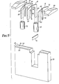
- Figure 5 shows an exploded view of the composite magnetic core.
- read/write ferrite core 10 containing effective gap 26 is shown sandwiched between erase ferrite cores 12 and 14 containing effective gaps 28.
- Support bar 24 is shown sandwiching the three ferrite cores 10, 12 and 14 to provide additional physical support.
- Read/write coil 18 is shown being slipped over the outer leg 40 of read/write ferrite core 10 and erase coil 30 is shown to be slipped over the outer legs 48 of the combined erase ferrite cores 12 and 14.
- a ferrite bar 16 is shown to magnetically connect the two legs (40 and 42) of the U-shape read-write ferrite core 10.
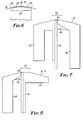
- FIG. 6 illustrates in a cross-sectional close-up diagram the detail of the scrub surface 22 of the ferrite cores and of the yoke assemblies.
- the scrub surface 22 is shown in cross-sectional view with the record carrier 32 passing over. Note again that the record carrier 32 is shown spaced from the scrub surface 22 for clarity. Note also that the scrub surface 22 is composed of three segments 34, 36 and 38.
- the central segment 36 at the center of which is the read/write effective gap 26, is seen composed of a segment of a circle. In the planar view, of course, this circle would translate to a segment of a cylinder running the entire length of the top surface of the yoke.
- the outer segments 34 and 38 of the scrub surface 22 comprise a straight, flat linear plane.
- the erase effective gaps 28 are illustrated as being positioned approximately at the juncture between the central segment 36 and one of the outer segments, in this case 34. It can be seen that the record carrier 32 comes in most intimate contact with segment 36 with the read/write effective gap 26 located at the very center of segment 36, therefore read/write effective gap 26 would have the most intimate contact with the record carrier 32.
- the erase effective gaps 28, although off-set from the center, located at the edge of the cylindrical portion of the scrub surface 22 will maintain fairly intimate contact with the record carrier 32.
- Figure 7 illustrates a side view in more detail of the read/write ferrite core 10.
- the ferrite portions of the read/write ferrite core 10 are illustrated by members 40 and 42.
- Member 42 is a ferrite material consisting approximately of a straight bar while ferrite member 40 is constructed in a dog-leg shape.
- the members 40 and 42 come together and comprise the effective gap 26.
- ferrite members 40 and 42 are joined together by a glass bond illustrated by glass material 44.
- the left-hand side of the read/write ferrite core 10 is constructed of a non-magnetic member 45 to provide spacing between the erase ferrite cores 12 and 14 upon assembly.
- the ferrite material used for members 40 and 42 would be a magnetic ferrite such as a composition of manganese zinc ferrite or nickel zinc ferrite.
- the glass bond procedure and material illustrated at 44 to produce the effective gap 26 is well known in the magnetic recording art.
- the non-magnetic member 45 in one embodiment consists of a ceramic material and in one embodiment consists of either barium titanate, or calcium titanate which may be bonded to ferrite member 42 in a conventional manner.
- the read/write effective gap 26 would be approximately 45 to 50 micro-inches. Also in one embodiment, the thickness of the read/write ferrite core 10 would be approximately .009 of an inch (0.2286 millimeters).
- the angle at which the shoulder of members 40 and 45 are angled down from the relatively flat scrub surface 22 is not critical and may be selected as a design choice consistent with avoiding contact with the record carrier. In a preferred embodiment, this angle is approximately 10 degrees.
- the length and thickness of the ferrite members 40 and 42 again is primarily a matter of design choice. In one embodiment, however, the members are about 1/4 of an inch (0.635 centimeters) long with member 40 being approximately .050 (0.127 centimeters) of an inch wide and member 42 approximately .010 (0.0254 centimeters) of an inch wide.
- Figure 8 illustrates the erase ferrite cores 12 and 14 in more detail.
- the erase ferrite cores 12 and 14 consist substantially of a U-shape comprised of members 46 and 48.
- Member 46 is constructed of a ferrite material substantially consisting of a straight linear bar
- member 48 also constructed of the ferrite material consists of a dog-leg shaped piece of material connected at the top by a glass bond 50 and creating the erase effective gap 28.
- Member 52 is a non-magnetic spacer designed to support the ferrite portion of the read/write ferrite core 10 when the assembly is complete.
- the ferrite portions of the erase ferrite cores 12 and 14 may be constructed of a similar magnetic ferrite to the read/write ferrite core 10.
- non-magnetic material 52 may be constructed of a ceramic material, such are barium titanate or calcium titanate.
- the effective gap 28 may be any number of which, which is primarily design choice. In one preferred embodiment, this effective gap 28 is approximately 80 micro-inches wide.
- the thickness of the erase ferrite cores 12 and 14 in one embodiment may be approximately .005 of an inch.
- the width of the scrub surface 22 in one embodiment may be approximately .040 of an inch (0.1016 centimeters).
- the remaining members of the erase ferrite cores 12 and 14 may be constructed similarly to the read/write ferrite core 10.
- the yoke 20 and other non-magnetic portions of the composite magnetic head may be constructed of a ceramic material, such as the barium titanate or calcium titanate utilized in the construction of the core assembly. It is significant that the barium titanate or calcium titanate ceramic material utilized for the non-magnetic parts has a wear composition which is similar to the nickel-zinc composition utilized for the ferrite material. This will enable the entire composite magnetic head to wear relatively evenly as the record carrier moves back and forth in a transverse direction overthe composite magnetic head assembly.
- the ceramic material and the ferrite materials may also be desirable to construct the ceramic material and the ferrite materials in a manner sufficient so that the temperature coefficient of expansion of the two materials are approximately the same to facilitate ease of manufacture, as for example during glass bonding, and to enable the composite magnetic head to operate over a wide range of temperatures.
- the present invention provides a composite magnetic head which may be easily utilized in a multitrack environment of a record carrier and which will maintain intimate contact between the record carrier and the composite magnetic head and support the record carrier over the entire range of tracks to be recorded or read.
Landscapes
- Engineering & Computer Science (AREA)
- Manufacturing & Machinery (AREA)
- Magnetic Heads (AREA)
Abstract
Claims (6)
Applications Claiming Priority (2)
| Application Number | Priority Date | Filing Date | Title |
|---|---|---|---|
| US06/072,242 US4300179A (en) | 1979-09-04 | 1979-09-04 | Composite magnetic head with multitrack support structure |
| US72242 | 1979-09-04 |
Publications (3)
| Publication Number | Publication Date |
|---|---|
| EP0035542A1 EP0035542A1 (fr) | 1981-09-16 |
| EP0035542A4 EP0035542A4 (fr) | 1982-01-11 |
| EP0035542B1 true EP0035542B1 (fr) | 1985-03-06 |
Family
ID=22106422
Family Applications (1)
| Application Number | Title | Priority Date | Filing Date |
|---|---|---|---|
| EP80901817A Expired EP0035542B1 (fr) | 1979-09-04 | 1981-03-23 | Tetes magnetiques composites avec structure de support a multipistes |
Country Status (6)
| Country | Link |
|---|---|
| US (1) | US4300179A (fr) |
| EP (1) | EP0035542B1 (fr) |
| BR (1) | BR8008814A (fr) |
| DE (1) | DE3070251D1 (fr) |
| IT (1) | IT1148268B (fr) |
| WO (1) | WO1981000780A1 (fr) |
Families Citing this family (15)
| Publication number | Priority date | Publication date | Assignee | Title |
|---|---|---|---|---|
| US4686596A (en) * | 1985-06-27 | 1987-08-11 | Minnesota Mining And Manufacturing Company | Recording head core yoke and method of manufacture |
| US4849841A (en) * | 1987-04-10 | 1989-07-18 | Irwin Magnetic Systems, Inc. | Transducer head core structure with recessed magnetic closures |
| US5055959A (en) * | 1990-01-09 | 1991-10-08 | Digital Equipment Corporation | Tape head with low spacing loss produced by narrow and wide wear regions |
| US5124866A (en) * | 1990-02-01 | 1992-06-23 | Minnesota Mining And Manufacturing Company | Recording head core yoke with full length core support |
| US5179486A (en) * | 1990-09-06 | 1993-01-12 | Minnesota Mining And Manufacturing Company | Head positioning and tape support apparatus for data recorder |
| US5426551A (en) * | 1993-07-19 | 1995-06-20 | Quantum Corp. | Magnetic contact head having a composite wear surface |
| JPH09503606A (ja) * | 1993-07-19 | 1997-04-08 | クウォンタム・コーポレイション | 自己調節摩耗領域を有する磁気ヘッド |
| NL1013553C2 (nl) * | 1999-11-11 | 2001-05-14 | Onstream B V | Bandgeleidingsinrichting voor een magnetisch element op actuator. |
| NL1015833C2 (nl) * | 2000-07-28 | 2002-01-29 | Onstream B V | Werkwijze voor het vervaardigen van een magneetkop. |
| US6937435B2 (en) * | 2003-05-16 | 2005-08-30 | Quantum Corporation | Tape head with thin support surface and method of manufacture |
| US7154691B2 (en) * | 2003-12-18 | 2006-12-26 | Quantum Corporation | Multi-format thinfilm head and associated methods |
| US8264793B2 (en) * | 2004-01-30 | 2012-09-11 | International Business Machines Corporation | Tape head with facing beams each having a head chip positioned in a recess thereof |
| US7256963B2 (en) * | 2004-09-16 | 2007-08-14 | Quantum Corporation | Magnetic head with adaptive data island and mini-outrigger and methods of manufacture |
| US7271983B2 (en) * | 2004-09-16 | 2007-09-18 | Quantum Corporation | Magnetic head with mini-outriggers and method of manufacture |
| US20070183091A1 (en) * | 2006-02-03 | 2007-08-09 | Saliba George A | Read/write head having varying wear regions and methods of manufacture |
Family Cites Families (12)
| Publication number | Priority date | Publication date | Assignee | Title |
|---|---|---|---|---|
| US3353168A (en) * | 1964-04-09 | 1967-11-14 | Potter Instrument Co Inc | Wide-record narrow-read magnetic head |
| NL156849B (nl) * | 1966-09-15 | 1978-05-16 | Philips Nv | Magnetische schrijf-lees-wiskop. |
| NL156528B (nl) * | 1966-09-15 | 1978-04-17 | Philips Nv | Magnetische schrijf-lees-wiskop. |
| US3582917A (en) * | 1968-12-13 | 1971-06-01 | Ibm | Magnetic head having a continuously variable radius of curvature |
| US3660892A (en) * | 1969-09-10 | 1972-05-09 | Matsushita Electric Ind Co Ltd | Method for making a multi-channel magnetic head |
| JPS4838826U (fr) * | 1971-09-10 | 1973-05-14 | ||
| US3787963A (en) * | 1973-02-05 | 1974-01-29 | Honeywell Inf Systems | Method of fabricating a multi-head magnetic transducer assembly |
| US3846840A (en) * | 1973-08-10 | 1974-11-05 | Ibm | Read/write and longitudinal edge erase head assembly having multiple similarly shaped layers |
| US3964103A (en) * | 1975-05-19 | 1976-06-15 | Shugart Associates, Inc. | Magnetic transducer with trim erase and housing therefor |
| US4110804A (en) * | 1977-07-21 | 1978-08-29 | International Business Machines Corporation | Read/write and tunnel erase magnetic head assembly |
| US4152742A (en) * | 1977-10-31 | 1979-05-01 | Nortronics Company, Inc. | Back bar retainer for magnetic head |
| US4164781A (en) * | 1978-04-11 | 1979-08-14 | Decitek | Track servoing system using signals from tunnel erase heads |
-
1979
- 1979-09-04 US US06/072,242 patent/US4300179A/en not_active Expired - Lifetime
-
1980
- 1980-06-23 WO PCT/US1980/000784 patent/WO1981000780A1/fr active IP Right Grant
- 1980-06-23 DE DE8080901817T patent/DE3070251D1/de not_active Expired
- 1980-06-23 BR BR8008814A patent/BR8008814A/pt unknown
- 1980-09-03 IT IT49604/80A patent/IT1148268B/it active
-
1981
- 1981-03-23 EP EP80901817A patent/EP0035542B1/fr not_active Expired
Non-Patent Citations (1)
| Title |
|---|
| IBM TECHNICAL DISCLOSURE BULLETIN, vol. 6, no. 10, March 1964, page 80 New York, US L.M. COOPER: "Read-record at 45 degrees" * |
Also Published As
| Publication number | Publication date |
|---|---|
| DE3070251D1 (en) | 1985-04-11 |
| US4300179A (en) | 1981-11-10 |
| BR8008814A (pt) | 1981-06-23 |
| EP0035542A1 (fr) | 1981-09-16 |
| IT1148268B (it) | 1986-11-26 |
| EP0035542A4 (fr) | 1982-01-11 |
| IT8049604A0 (it) | 1980-09-03 |
| WO1981000780A1 (fr) | 1981-03-19 |
Similar Documents
| Publication | Publication Date | Title |
|---|---|---|
| EP0035542B1 (fr) | Tetes magnetiques composites avec structure de support a multipistes | |
| US8587905B2 (en) | Multi-channel tape head having asymmetric channel arrays | |
| US5296993A (en) | Magnetic head with magnetic substrate and an enhanced poletip thereon | |
| US3846840A (en) | Read/write and longitudinal edge erase head assembly having multiple similarly shaped layers | |
| US6172837B1 (en) | Postponable servo code selection | |
| US4367505A (en) | Magnetic head assembly with skewed read/write gap | |
| US5148342A (en) | Magnetic head having a filler plate arranged between two magnetic core assemblies | |
| US5041936A (en) | Magnetic recording transducer assembly with two gaps of different length | |
| JPH0542047B2 (fr) | ||
| US5251089A (en) | Magnetic head | |
| JPH02244420A (ja) | 浮動型磁気ヘッド | |
| US4458280A (en) | Servo writing transducer design and writing method | |
| US5229903A (en) | Magnetic head with inclined core | |
| JPH0610846B2 (ja) | 磁気ヘツド | |
| EP0174714A1 (fr) | Stucture de tête de transducteur magnétique et son procédé d'utilisation | |
| JPH04143911A (ja) | 磁気ヘッド | |
| JPH04149816A (ja) | 磁気ヘッド | |
| JP3194534B2 (ja) | 磁気ヘッドとその製造方法 | |
| JP2573917B2 (ja) | 磁気ヘツド | |
| JP2911165B2 (ja) | 磁気ヘッド | |
| JPH03181007A (ja) | 磁気ヘッド | |
| JP2522615Y2 (ja) | 磁気ヘツド | |
| JPH0317806A (ja) | 磁気ヘッド | |
| JPH08102169A (ja) | 磁気ディスク装置 | |
| JPS62124618A (ja) | 磁気ヘツドおよびその製造方法 |
Legal Events
| Date | Code | Title | Description |
|---|---|---|---|
| PUAI | Public reference made under article 153(3) epc to a published international application that has entered the european phase |
Free format text: ORIGINAL CODE: 0009012 |
|
| AK | Designated contracting states |
Designated state(s): DE FR GB |
|
| 17P | Request for examination filed |
Effective date: 19810908 |
|
| GRAA | (expected) grant |
Free format text: ORIGINAL CODE: 0009210 |
|
| AK | Designated contracting states |
Designated state(s): DE FR GB |
|
| REF | Corresponds to: |
Ref document number: 3070251 Country of ref document: DE Date of ref document: 19850411 |
|
| ET | Fr: translation filed | ||
| PLBE | No opposition filed within time limit |
Free format text: ORIGINAL CODE: 0009261 |
|
| STAA | Information on the status of an ep patent application or granted ep patent |
Free format text: STATUS: NO OPPOSITION FILED WITHIN TIME LIMIT |
|
| 26N | No opposition filed | ||
| PGFP | Annual fee paid to national office [announced via postgrant information from national office to epo] |
Ref country code: FR Payment date: 19900515 Year of fee payment: 11 |
|
| PGFP | Annual fee paid to national office [announced via postgrant information from national office to epo] |
Ref country code: DE Payment date: 19900521 Year of fee payment: 11 |
|
| PGFP | Annual fee paid to national office [announced via postgrant information from national office to epo] |
Ref country code: GB Payment date: 19900525 Year of fee payment: 11 |
|
| PG25 | Lapsed in a contracting state [announced via postgrant information from national office to epo] |
Ref country code: GB Effective date: 19910623 |
|
| GBPC | Gb: european patent ceased through non-payment of renewal fee | ||
| PG25 | Lapsed in a contracting state [announced via postgrant information from national office to epo] |
Ref country code: FR Effective date: 19920228 |
|
| PG25 | Lapsed in a contracting state [announced via postgrant information from national office to epo] |
Ref country code: DE Effective date: 19920401 |
|
| REG | Reference to a national code |
Ref country code: FR Ref legal event code: ST |