EP0034242A1 - Space-air heating device - Google Patents
Space-air heating device Download PDFInfo
- Publication number
- EP0034242A1 EP0034242A1 EP81100070A EP81100070A EP0034242A1 EP 0034242 A1 EP0034242 A1 EP 0034242A1 EP 81100070 A EP81100070 A EP 81100070A EP 81100070 A EP81100070 A EP 81100070A EP 0034242 A1 EP0034242 A1 EP 0034242A1
- Authority
- EP
- European Patent Office
- Prior art keywords
- heating circuit
- additional
- heat exchanger
- main
- circuit
- Prior art date
- Legal status (The legal status is an assumption and is not a legal conclusion. Google has not performed a legal analysis and makes no representation as to the accuracy of the status listed.)
- Granted
Links
Images

Classifications
-
- B—PERFORMING OPERATIONS; TRANSPORTING
- B60—VEHICLES IN GENERAL
- B60H—ARRANGEMENTS OF HEATING, COOLING, VENTILATING OR OTHER AIR-TREATING DEVICES SPECIALLY ADAPTED FOR PASSENGER OR GOODS SPACES OF VEHICLES
- B60H1/00—Heating, cooling or ventilating [HVAC] devices
- B60H1/22—Heating, cooling or ventilating [HVAC] devices the heat being derived otherwise than from the propulsion plant
-
- B—PERFORMING OPERATIONS; TRANSPORTING
- B60—VEHICLES IN GENERAL
- B60H—ARRANGEMENTS OF HEATING, COOLING, VENTILATING OR OTHER AIR-TREATING DEVICES SPECIALLY ADAPTED FOR PASSENGER OR GOODS SPACES OF VEHICLES
- B60H1/00—Heating, cooling or ventilating [HVAC] devices
- B60H1/02—Heating, cooling or ventilating [HVAC] devices the heat being derived from the propulsion plant
- B60H1/03—Heating, cooling or ventilating [HVAC] devices the heat being derived from the propulsion plant and from a source other than the propulsion plant
-
- F—MECHANICAL ENGINEERING; LIGHTING; HEATING; WEAPONS; BLASTING
- F24—HEATING; RANGES; VENTILATING
- F24D—DOMESTIC- OR SPACE-HEATING SYSTEMS, e.g. CENTRAL HEATING SYSTEMS; DOMESTIC HOT-WATER SUPPLY SYSTEMS; ELEMENTS OR COMPONENTS THEREFOR
- F24D7/00—Central heating systems employing heat-transfer fluids not covered by groups F24D1/00 - F24D5/00, e.g. oil, salt or gas
-
- F—MECHANICAL ENGINEERING; LIGHTING; HEATING; WEAPONS; BLASTING
- F24—HEATING; RANGES; VENTILATING
- F24V—COLLECTION, PRODUCTION OR USE OF HEAT NOT OTHERWISE PROVIDED FOR
- F24V40/00—Production or use of heat resulting from internal friction of moving fluids or from friction between fluids and moving bodies
- F24V40/10—Production or use of heat resulting from internal friction of moving fluids or from friction between fluids and moving bodies the fluid passing through restriction means
Definitions
- the invention relates to a device for heating room air with a main heat exchanger in a main heating circuit, which is heated by waste heat from a machine, preferably the internal combustion engine of a vehicle.
- a device for heating the control cabin of a machine in which heated lubricating oil of an internal combustion engine is fed to a heat exchanger in the control cabin (DE-PS 26 23 621).
- This heater is fully functional when the engine is warm, but offers only slow heating during the warm-up phase and insufficient heating when idling.
- the z. B. are characteristic of inner-city traffic, the heat requirement for fast, possibly repeated heating of the cabin and keeping the windows clear is particularly high.
- the task is to design a device that maintains the tried and tested devices for continuous operation under normal conditions and for the previously insufficiently supplied operating phases or for difficult operating conditions also provides a completely or largely independent device that increases the amount of heat that is already available sufficient amount increased.
- the solution according to the invention consists of an additional heating circuit with a hydraulic pump, a pressure reduction element, for. B. a throttle, and an additional heat exchanger.
- This provides a device with a liquid heating medium that provides the required additional amount of heat in an additional heat exchanger in a low-maintenance, easy-to-install, preferably driven by the existing machine solely by building up pressure in the hydraulic pump and converting it into heat in the pressure reduction element.
- the additional heating circuit can be installed completely independently according to the possibilities, in particular with regard to the arrangement of the hydraulic pump on a suitable drive and the arrangement of the additional heat exchanger in accordance with the spatial conditions.
- the additional devices have very small dimensions and can be combined in a favorable manner, with the exception of the heat exchanger, to form a compact component which can easily be fitted to an existing engine.
- a combination of the auxiliary heating circuit is not only possible with a main heating circuit, in the engine Lubricating oil serves as a heating medium, but also with such facilities in which, for. B. cooling water or hydraulic oil absorb the waste heat of a machine or the frictional heat from working devices.
- the additional heat exchanger is arranged in series with the main heat exchanger on the air side and is preferably attached behind the main heat exchanger.
- the heating air ducts, control flaps and blowers can remain unchanged. The order of the arrangement results from the fact that the additional heating circuit heats up faster and has a higher temperature level, so that the heat of the main heating circuit causes the preheating of the heating air to increase as the temperature slowly increases.
- the additional heating circuit is self-contained and sealed according to the invention. Evaporation during pressure reduction in the additional heating circuit can also be avoided by increasing the pressure level.
- Various solutions according to the invention are available for the selection of the heating means for the two circuits.
- a water-cooled internal combustion engine for example, it is favorable to connect the main heating circuit with the cooling water system and the additional heating circuit with the lubricating oil system, since the largest proportion of the usable waste heat is transferred to the cooling water and because the lubricating oil already provides a suitable heating medium for increasing the pressure. It is also advantageous that the lubricating oil is heated more quickly and that a further proportion of the waste heat is available as heating heat when the engine is warm. If a hydraulic system is available, the additional heating circuit can be connected to it, especially since hydraulic oil is particularly suitable for the intended pressure increase.
- the main heating circuit and the additional heating circuit can preferably be connected to one another via a common collecting container.
- the oil pan is particularly suitable for this in systems with an internal combustion engine.
- a connection line between the circuits with a return flap blocking the flow to the additional heating circuit can also be provided in the arrangement mentioned. If there is sufficient heating available in the main heating circuit, the hydraulic pump can be stopped, which means that the additional heat exchanger is connected via the connecting line the opening check valve will be included in the main heating circuit. This increases the effective heat exchanger surface in this circuit, which improves the heating effect. The same effect is achieved in that the hydraulic pump, which continues to operate, delivers pressure via an adjustable directional valve and a control line into the collecting container or to the suction side.
- the rapid increase in temperature in the additional heating circuit can be significantly impaired by the fact that the collecting container, in particular a common collecting container for both circuits, has a large heating medium content which initially absorbs a considerable part of the heat generated at the pressure reduction element. If this is the case, a quantity divider in the additional heating circuit can be used for. B. caused temperature or time dependent, that the circulating amount is partially or completely bypassed by bypassing the collecting container and heated.
- the flow divider can be arranged behind the additional heat exchanger, or in front of the heat exchanger so that a significant increase in temperature takes place before a first application.
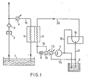
- the main heating circuit 10 has a collecting container 1 with a heating medium filling, which absorbs waste heat from a machine at any point in the circuit.
- the heating medium is supplied by a pump 2 of a suitable design to the main heat exchanger 5 via a filter 3 and flows back into a collecting tank 1.
- the main heating circuit 10 is branched behind the filter 3 and leads in a manner not shown, which also leads back into the collecting tank 1. parallel to the main heat exchanger 5 to other assemblies of the machine in question. Depending on the type of circuit, this can be water spaces of a machine to be cooled, pressure oil consumers, lubrication points or other.
- the flow rate to the main heat exchanger 5 is to be adjusted or regulated by a throttle 4.
- the main heating circuit 10 can also be unbranched in series connection of all modules including the main heat exchanger 5 can be designed.
- the additional heating circuit 20 also has a collecting container 6, with a particularly pressure-resistant heating medium filling. This is conveyed by a hydraulic pump 7 via a pressure reduction element 8 to the additional heat exchanger 9, which is preferably combined in series with the main heat exchanger 5 on the air side.
- the auxiliary heating circuit 20 is branched and has several control devices. Behind the additional heat exchanger 9 is a flow divider 18, the z. B. time-dependent or preferably temperature or viscosity-dependent, regulates the flow ratio between a return line 11 to the collecting container 6 and a short-circuit line 12 to the suction side of the hydraulic pump 7.
- a directional control valve 13 is arranged on the pressure side, which controls a control line 14 leading to the collecting container 6. If there is sufficient heat in the additional heating circuit, a bypass line 16 can be opened parallel to the pressure reduction element 8 via a control element 15.
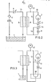
- the main heating circuit 10 is carried out in the same way as in Fig. 1, the additional heating circuit 20 is self-contained and has a fill level expansion tank 17 instead of a collecting tank.
- FIG. 3 alone a special embodiment of the additional heating circuit 20 shown in FIG. 2 is shown with a directional control valve 18 between the pressure reduction element 8 and the additional heat exchanger 9, which, until sufficiently heated, heats a partial amount via the short-circuit line 12 into a rapidly warming circuit with the hydraulic pump 7 controls.
- a directional control valve 13 with a control line 14 for restricting heat generation is also shown.
- a connection for operation with a uniform heating medium is established between the main heating circuit 10 and the additional heating circuit 20 via a common collecting container 1 and via a connecting line 21 with a check valve or check valve 19.
- the hydraulic pump 7 can draw in from the collecting container 1 or from the main heating circuit behind the pump 2 or the filter 3.
- a second directional valve 22 in the auxiliary heating circuit 20 is arranged behind the pressure reduction element 8 and connected to the control line 14 by a line 23. It offers the possibility of additional heating of the heating medium in the pressure reduction element 8 without a direct application of additional heat exchanger 9.
Abstract
Ein Heizungssystems mit einem Hauptheizkreislauf (10), der Abwärme einer Machine mittels eines flüssigen Heizmediums über einen Wärmetauscher (5) nutzbar macht, wird für erhöhten Heizbedarf durch einen Zusatzkreislauf (20) verbessert, der eine Pumpe (7), eine Drossel (8) und einen weiteren Wärmetauscher (9) enthält. In der Pumpe (7) wird einem ebenfalls flüssigen Heizmedium Energie zugeführt, die in der Drossel (8) in Wärme umgesetzt wird. Der Hauptheizkreislauf (10) ist vorzugsweise mit dem Kühlwasser- oder Schmierölsystem einer Brennkraftmaschine integriert. Hauptheizkreislauf (10) und Zusatzheizkreislauf (20) können getrennt oder bei identischem Heizmedium miteinander verbunden sein. Zur Regelung der Wärmeerzeugung und -übertragung sind in beiden Kreisläufen (10, 20) Reguliereinrichtungen (4, 13, 15) vorgesehen.A heating system with a main heating circuit (10) which makes waste heat from a machine usable by means of a liquid heating medium via a heat exchanger (5) is improved for increased heating requirements by an additional circuit (20) which has a pump (7), a throttle (8) and contains a further heat exchanger (9). In the pump (7), a liquid heating medium is also supplied with energy, which is converted into heat in the throttle (8). The main heating circuit (10) is preferably integrated with the cooling water or lubricating oil system of an internal combustion engine. The main heating circuit (10) and additional heating circuit (20) can be separated or connected to one another if the heating medium is identical. Regulating devices (4, 13, 15) are provided in both circuits (10, 20) for regulating heat generation and transmission.
Description
Die Erfindung betrifft eine Einrichtung zum Aufheizen von Raumluft mit einem Hauptwärmetauscher in einem Hauptheizkreislauf, der von Abwärme einer Maschine, vorzugsweise der Brennkraftmaschine eines Fahrzeuges, erwärmt wird.The invention relates to a device for heating room air with a main heat exchanger in a main heating circuit, which is heated by waste heat from a machine, preferably the internal combustion engine of a vehicle.
Es ist eine Einrichtung zum Beheizen der Bedienungskabine einer Maschine bekannt, in der erwärmtes Schmieröl einer Brennkraftmaschine einem Wärmetauscher in der Bedienungskabine zugeführt wird (DE-PS 26 23 621). Diese Heizung ist bei betriebswarmem Motor voll funktionsfähig, bietet jedoch in der Warmlaufphase nur langsam und bei Leerlaufbetrieb nur unzureichend Heizwärme an. Gerade in diesen Betriebszuständen, die z. B. für innerstädtischen Verkehr bezeichnend sind, ist der Wärmebedarf zum schnellen, ggfs. wiederholten Aufheizen der Kabine und zum Freihalten der Scheiben besonders hoch.A device for heating the control cabin of a machine is known in which heated lubricating oil of an internal combustion engine is fed to a heat exchanger in the control cabin (DE-PS 26 23 621). This heater is fully functional when the engine is warm, but offers only slow heating during the warm-up phase and insufficient heating when idling. Especially in these operating conditions, the z. B. are characteristic of inner-city traffic, the heat requirement for fast, possibly repeated heating of the cabin and keeping the windows clear is particularly high.
Daher ist die Aufgabe gestellt, eine Einrichtung zu entwerfen, die für den Dauerbetrieb unter normalen Bedingungen die hierfür bewährten Einrichtungen beibehält und für die bislang unzureichend versorgten Betriebsphasen oder für erschwerte Betriebsverhältnisse eine ganz oder weitgehend unabhängige Einrichtung zusätzlich vorsieht, die die bereits verfügbare Wärmemenge um einen ausreichenden Betrag erhöht.Therefore, the task is to design a device that maintains the tried and tested devices for continuous operation under normal conditions and for the previously insufficiently supplied operating phases or for difficult operating conditions also provides a completely or largely independent device that increases the amount of heat that is already available sufficient amount increased.
Die Lösung besteht erfindungsgemäß aus einem Zusatzheizkreislauf mit einer Hydraulikpumpe, einem Druckabbauelement, z. B. einer Drossel, und einem Zusatzwärmetauscher.The solution according to the invention consists of an additional heating circuit with a hydraulic pump, a pressure reduction element, for. B. a throttle, and an additional heat exchanger.
Hiermit ist eine Einrichtung mit einem flüssigen Heizmittel gegeben, die wartungsgünstig, einbaufreundlich, vorzugsweise von der vorhandenen Maschine angetrieben allein durch Druckaufbau in der Hydraulikpumpe und Umwandlung in Wärme im Druckabbauelement .die erforderliche Zusatzwärmemenge in einem Zusatzwärmetauscher zur Verfügung stellt.This provides a device with a liquid heating medium that provides the required additional amount of heat in an additional heat exchanger in a low-maintenance, easy-to-install, preferably driven by the existing machine solely by building up pressure in the hydraulic pump and converting it into heat in the pressure reduction element.
Sie bietet den Vorteil, daß die bewährte Heizungseinrichtung mit den vorhandenen Luftführungen, Verstelleinrichtungen und dergl. nicht geändert werden muß und daß die zusätzliche Einrichtung nur für eine Grundlast bzw. Spitzenlast auszulegen ist. Hierbei kann der Zusatzheizkreislauf völlig unabhängig nach den gegebenen Möglichkeiten angebracht werden, insbesondere bezüglich der Anordnung der Hydraulikpumpe an einem geeigneten Antrieb und der Anordnung des Zusatzwärmetauschers entsprechend den räumlichen Verhältnissen. Die zusätzlichen Einrichtungen haben sehr geringe Abmessungen und können in günstiger Weise, mit Ausnahme des Wärmetauschers, zu einem kompakten Bauteil zusammengefaßt werden, das leicht an einem vorhandenen Motor Platz findet. Eine Kombination des Zusatzheizkreislaufs ist nicht nur mit einem Hauptheizkreislauf möglich,.in dem Motorschmieröl als Heizmittel dient, sondern daneben auch mit solchen Einrichtungen, in denen z. B. Kühlwasser oder Hydrauliköl die Abwärme einer Maschine bzw. die Reibungswärme aus Arbeitsvorrichtungen aufnehmen.It has the advantage that the proven heating device with the existing air ducts, adjusting devices and the like does not have to be changed and that the additional device is only to be designed for a base load or peak load. Here, the additional heating circuit can be installed completely independently according to the possibilities, in particular with regard to the arrangement of the hydraulic pump on a suitable drive and the arrangement of the additional heat exchanger in accordance with the spatial conditions. The additional devices have very small dimensions and can be combined in a favorable manner, with the exception of the heat exchanger, to form a compact component which can easily be fitted to an existing engine. A combination of the auxiliary heating circuit is not only possible with a main heating circuit, in the engine Lubricating oil serves as a heating medium, but also with such facilities in which, for. B. cooling water or hydraulic oil absorb the waste heat of a machine or the frictional heat from working devices.
Der Zusatzwärmetauscher wird in besonderer erfindungsgemäßer Ausführung mit dem Hauptwärmetauscher luftseitig in Reihenschaltung angeordnet und dabei vorzugsweise hinter dem Hauptwärmetauscher angebracht. Hierbei können die Heizluftführungen, Steuerklappen und Gebläse unverändert bleiben. Die Reihenfolge der Anordnung ergibt sich aus der Tatsache, daß sich der Zusatzheizkreislauf schneller erwärmt und ein höheres Temperaturniveau hat, so daß die Wärme des Hauptheizkreislaufes bei langsam steigender Temperatur eine zunehmende Vorwärmung der Heizluft bewirkt.In a special embodiment according to the invention, the additional heat exchanger is arranged in series with the main heat exchanger on the air side and is preferably attached behind the main heat exchanger. The heating air ducts, control flaps and blowers can remain unchanged. The order of the arrangement results from the fact that the additional heating circuit heats up faster and has a higher temperature level, so that the heat of the main heating circuit causes the preheating of the heating air to increase as the temperature slowly increases.
Sowohl in Bezug auf den Einbau als auch auf die Wärmeübertragung ist es besonders günstig, den Haupt- und den Zusatzwärmetauscher zu einem Bauelement mit Gegenstrom oder Kreuzstrom der beiden Heizmittelströme zusammenzufassen.In terms of both installation and heat transfer, it is particularly advantageous to combine the main and additional heat exchangers into one component with counterflow or crossflow of the two heating medium streams.
Eine besondere Wartungsvereinfachung ist dadurch möglich, daß der Zusatzheizkreislauf erfindungsgemäß in sich abgeschlossen und versiegelt ausgeführt wird. Hierbei können außerdem durch ein erhöhtes Druckniveau Verdampfungserscheinungen beim Druckabbau im Zusatzheizkreislauf vermieden werden. Für die Auswahl der Heizmittel für die beiden Kreisläufe bieten sich verschiedene erfindungsgemäße Lösungen an. So ist es bei einer wassergekühlten Brennkraftmaschine günstig, den Hauptheizkreislauf mit dem Kühlwassersystem und den Zusatzheizkreislauf mit dem Schmierölsystem zu verbinden, da der größte Anteil der nutzbaren Abwärme auf das Kühlwasser übergeht und da mit dem Schmieröl ein für die Druckerhöhung geeignetes Heizmittel bereits zur Verfügung steht. Weiterhin ist dabei vorteilhaft, daß das Schmieröl schneller erwärmt wird und daß bei warmem Motor ein weiterer Anteil der Abwärme als Heizwärme verfügbar ist. Sofern ein Hydrauliksystem vorhanden ist, kann der Zusatzheizkreislauf an dieses angeschlossen werden, zumal Hydrauliköl in besonderer Weise für die vorgesehene Druckerhöhung geeignet ist.A special simplification of maintenance is possible in that the additional heating circuit is self-contained and sealed according to the invention. Evaporation during pressure reduction in the additional heating circuit can also be avoided by increasing the pressure level. Various solutions according to the invention are available for the selection of the heating means for the two circuits. In a water-cooled internal combustion engine, for example, it is favorable to connect the main heating circuit with the cooling water system and the additional heating circuit with the lubricating oil system, since the largest proportion of the usable waste heat is transferred to the cooling water and because the lubricating oil already provides a suitable heating medium for increasing the pressure. It is also advantageous that the lubricating oil is heated more quickly and that a further proportion of the waste heat is available as heating heat when the engine is warm. If a hydraulic system is available, the additional heating circuit can be connected to it, especially since hydraulic oil is particularly suitable for the intended pressure increase.
Zur Vereinfachung der Einrichtung können der Hauptheizkreislauf und der Zusatzheizkreislauf vorzugsweise über einen gemeinsamen Sammelbehälter miteinander verbunden werden. Hierfür bietet sich bei Anlagen mit einer Brennkraftmaschine besonders die Ölwanne an. Zur Verbesserung der Wirksamkeit kann bei der genannten Anordnung außerdem eine Verbindungsleitung zwischen den Kreisläufen mit einer den Durchfluß zum Zusatzheizkreislauf sperrenden Rücklaufklappe vorgesehen werden. Bei ausreichendem Heizwärmeangebot im Hauptheizkreislauf kann die Hydraulikpumpe stillgesetzt werden, wodurch der Zusatzwärmetauscher über die Verbindungsleitung mit der sich öffnenden Rückschlagklappe in den Hauptheizkreislauf einbezoqen wird. Dadurch vergrößert sich die wirksame Wärmetauscheroberfläche in diesem Kreislauf, wodurch die Heizwirkung verbessert wird. Die gleiche Wirkung wird dadurch erreicht, daß die weiter betriebene Hydraulikpumpe über ein verstellbares Wegeventil und eine Absteuerleitung drucklos in den Sammelbehälter oder zur Ansaugseite fördert.To simplify the device, the main heating circuit and the additional heating circuit can preferably be connected to one another via a common collecting container. The oil pan is particularly suitable for this in systems with an internal combustion engine. In order to improve the effectiveness, a connection line between the circuits with a return flap blocking the flow to the additional heating circuit can also be provided in the arrangement mentioned. If there is sufficient heating available in the main heating circuit, the hydraulic pump can be stopped, which means that the additional heat exchanger is connected via the connecting line the opening check valve will be included in the main heating circuit. This increases the effective heat exchanger surface in this circuit, which improves the heating effect. The same effect is achieved in that the hydraulic pump, which continues to operate, delivers pressure via an adjustable directional valve and a control line into the collecting container or to the suction side.
Eine wesentliche Beeinträchtigung der schnellen Temperaturerhöhung im Zusatzheizkreislauf kann dadurch gegeben sein, daß der Sammelbehälter, insbesondere ein gemeinsamer Sammelbehälter für beide Kreisläufe, einen großen Heizmittelinhalt hat, der einen erheblichen Teil der am Druckabbauelement erzeugten Wärme zunächst aufnimmt. Ist dies gegeben, so kann durch einen Mengenteiler im Zusatzheizkreislauf z. B. temperatur- oder zeitabhängig bewirkt werden, daß die Umlaufmenge ganz oder teilweise unter Umgehung des Sammelbehälters im Kurzschluß gefördert und erwärmt wird. Dabei kann der Mengenteiler hinter dem Zusatzwärmetauscher, oder auch, damit vor einer ersten Beaufschlagung bereits eine wesentliche Temperatursteigerung erfolgt, vor dem Wärmetauscher angeordnet sein.The rapid increase in temperature in the additional heating circuit can be significantly impaired by the fact that the collecting container, in particular a common collecting container for both circuits, has a large heating medium content which initially absorbs a considerable part of the heat generated at the pressure reduction element. If this is the case, a quantity divider in the additional heating circuit can be used for. B. caused temperature or time dependent, that the circulating amount is partially or completely bypassed by bypassing the collecting container and heated. The flow divider can be arranged behind the additional heat exchanger, or in front of the heat exchanger so that a significant increase in temperature takes place before a first application.
Verschiedene Ausführungsbeispiele der Erfindung sind in den Abbildungen dargestellt und nachstehend näher erläutert.Various embodiments of the invention are shown in the figures and explained in more detail below.
- Fig. 1 zeigt einen Hauptheizkreislauf und einen Zusatzheizkreislauf mit getrennten Heizmittelsystemen,1 shows a main heating circuit and an additional heating circuit with separate heating medium systems,
- Fig. 2 zeigt einen offenen Hauptheizkreislauf und einen in sich abgeschlossenen, versiegelten Zusatzheizkreislauf,2 shows an open main heating circuit and a self-contained, sealed additional heating circuit,
- Fig. 3 zeigt einen in sich abgeschlossenen, versiegelten Zusatzheizkreislauf in besonderer Ausgestaltung,3 shows a self-contained, sealed additional heating circuit in a special embodiment,
- Fig. 4 zeigt einen Hauptheizkreislauf und einen Zusatzheizkreislauf mit einem gemeinsamen Heizmittelsystem.Fig. 4 shows a main heating circuit and an additional heating circuit with a common heating system.
In Fig. 1 weist der Hauptheizkreislauf 10 einen Sammelbehälter 1 mit einer Heizmittelfüllung auf, die an beliebiger Stelle im Kreislauf Abwärme einer Maschine aufnimmt. Das Heizmittel wird von einer Pumpe 2 geeigneter Bauart über einen Filter 3 dem Hauptwärmetauscher 5 zugeführt und fließt zurück in einen Sammelbehälter 1. Hinter dem Filter 3 ist der Hauptheizkreislauf 10 verzweigt und führt in einem nicht dargestellten Verlauf, der ebenfalls in den Sammelbehälter 1 zurückführt, parallel zum Hauptwärmetauscher 5 zu anderen Baugruppen der betreffenden Maschine. Dies können je nach Art der Kreisläufe Wasserräume einer zu kühlenden Maschine, Druckölverbraucher, Schmierstellen oder anderes sein. Der Mengenstrom zum Hauptwärmetauscher 5 ist durch eine Drossel 4 einzustellen oder zu regeln. Der Hauptheizkreislauf 10 kann auch unverzweigt in Reihenschaltung aller Baugruppen einschließlich des Hauptwärmetauschers 5 ausgelegt sein. Der Zusatzheizkreislauf 20 hat ebenfalls einen Sammelbehälter 6, mit einer besonders druckbeständigen Heizmittelfüllung. Diese wird von einer Hydraulikpumpe 7 über ein Druckabbauelement 8 zum Zusatzwärmetauscher 9 gefördert, der mit dem Hauptwärmetauscher 5 luftseitig vorzugsweise in Reihenschaltung zusammengefaßt ist. Der Zusatzheizkreislauf 20 ist verzweigt und weist mehrere Regeleinrichtungen auf. Hinter dem Zusatzwärmetauscher 9 befindet sich ein Mengenteiler 18, der z. B. zeitabhängig oder vorzugsweise temperatur- oder viskositätsabhängig das Mengenstromverhältnis zwischen einer Rücklaufleitung 11 zum Sammelbehälter 6 und einer Kurzschlußleitung 12 zur Saugseite der Hydraulikpumpe 7 regelt. Um den Mengenstrom zum Zusatzwärmetauscher 9 bei ununterbrochenem Antrieb der Hydraulikpumpe 7 zu steuern, ist auf der Druckseite ein Wegeventil 13 angeordnet, das eine zum Sammelbehälter 6 führende Absteuerleitung 14 beherrscht. Bei ausreichendem Wärmeangebot im Zusatzheizkreislauf kann über ein Steuerorgan 15 eine Bypaßleitung 16 parallel zum Druckabbauelement 8 geöffnet werden.In Fig. 1, the
In Fig. 2 ist der Hauptheizkreislauf 10 in gleicher Weise ausgeführt wie in Fig. 1, der Zusatzheizkreislauf 20 ist in sich geschlossen und hat anstelle eines Sammelbehälters einen Füllungsstandsausgleichsbehälter 17. Als Regeleinrichtungen sind das Wegeventil 13 mit der Absteuerleitung 14 und das Steuerorgan 15 mit der Bypaßleitung 16 vorzufinden.In Fig. 2, the
In Fig. 3 ist allein eine besondere Ausführung des Zusatzheizkreislaufs 20 nach Fig. 2 gezeigt mit einem Wegeventil 18 zwischen Druckabbauelement 8 und Zusatzwärmetauscher 9, das bis zur ausreichenden Erwärmung eine Heizmittel.teilmenge über die Kurzschlußleitung 12 in einen sich schnell erwärmdenden Kreislauf mit der Hydraulikpumpe 7 steuert. Ein Wegeventil 13 mit einer Absteuerleitung 14 zur Beschränkung der Wärmeerzeugung ist ebenfalls gezeigt.In Fig. 3 alone a special embodiment of the
In Fig. 4 ist zwischen dem Hauptheizkreislauf 10 und dem Zusatzheizkreislauf 20 über einen gemeinsamen Sammelbehälter 1 und über eine Verbindungsleitung 21 mit einer Rückschlagklappe bzw. Rückschlagventil 19 eine Verbindung für den Betrieb mit einem einheitlichen Heizmittel hergestellt. Die Hydraulikpumpe 7 kann, wie angedeutet, aus dem Sammelbehälter 1 oder aus dem Hauptheizkreislauf hinter der Pumpe 2 bzw. dem Filter 3 ansaugen. Ein zweites Wegeventil 22 im Zustzheizkreislauf 20 ist hinter dem Druckabbauelement 8 angeordnet und mit der Absteuerleitung 14 durch eine Leitung 23 verbunden. Sie bietet die Möglichkeit einer zusätzlichen Erwärmung des Heizmittels im Druckabbauelement 8 ohne unmittelbare Baaufschlagung des Zusatzwärmetauschers 9.In Fig. 4, a connection for operation with a uniform heating medium is established between the
Claims (13)
gekennzeichnet durch einen Zusatzheizkreislauf (20) mit einer Hydraulikpumpe (7), einem Druckabbauelement (8), z. B. einer Drossel, und einem Zusatzwärmetauscher (9).1. Device for heating room air with a main heat exchanger in a main heating circuit, which is heated by waste heat from a machine, preferably the internal combustion engine of a vehicle.
characterized by an additional heating circuit (20) with a hydraulic pump (7), a pressure reduction element (8), for. B. a throttle, and an additional heat exchanger (9).
dadurch gekennzeichnet, daß der Zusatzwärmetauscher (9) mit dem Hauptwärmetauscher (5) luftseitig in Reihenschaltung angeordnet ist und daß der Zusatzwärmetauscher (9) dabei vorzugsweise hinter dem Hauptwärmetauscher (5) angebracht ist.2. Device according to claim 1,
characterized in that the additional heat exchanger (9) is arranged in series with the main heat exchanger (5) on the air side, and in that the additional heat exchanger (9) is preferably arranged behind the main heat exchanger (5).
dadurch gekennzeichnet, daß der Hauptwärmetauscher (5) und der Zusatzwärmetauscher (9) zu einem Bauelement zusammengefaßt sind und daß der Hauptheizkreislauf (10) und der Zusatzheizkreislauf (20) darin flüssigkeitsseitig im Gegenstrom oder im Kreuzstrom verlaufen.3. Device according to one of claims 1 to 2,
characterized in that the main heat exchanger (5) and the additional heat exchanger (9) are combined to form one component and in that the main heating circuit (10) and the additional heating circuit (20) run in the countercurrent or crosscurrent on the liquid side.
dadurch gekennzeichnet, daß der Zusatzheizkreislauf (20) in sich abgeschlossen und versiegelt ist.4. Device according to one of claims 1 to 3,
characterized in that the additional heating circuit (20) is self-contained and sealed.
dadurch gekennzeichnet, daß der Hauptheizkreislauf (10) an ein Kühlwassersystem und der Zusatzheizkreislauf (20) an ein Schmierölsystem angeschlossen ist.5. Device according to one of claims 1 to 3,
characterized in that the main heating circuit (10) is connected to a cooling water system and the additional heating circuit (20) is connected to a lubricating oil system.
dadurch gekennzeichnet, daß der Hauptheizkreislauf (10) an ein Kühlwasser- oder Schmierölsystem und der Zusatzheizkreislauf (20) an das Hydrauliksystem angeschlossen ist.6. Device according to one of claims 1 to 3, with an additional hydraulic system,
characterized in that the main heating circuit (10) is connected to a cooling water or lubricating oil system and the additional heating circuit (20) is connected to the hydraulic system.
dadurch gekennzeichnet, daß der Hauptheizkreislauf (10) und der Zusatzheizkreislauf (20) durch einen gemeinsamen Sammelbehälter (1) oder dergl. miteinander verbünden sind.7. Device according to one of claims 1 to 3,
characterized in that the main heating circuit (10) and the additional heating circuit (20) are connected to one another by a common collecting container (1) or the like.
dadurch gekennzeichnet, daß unmittelbar vor den Wärmetauschern (5, 9) eine vom Hauptheizkreislauf (10) zum Zusatzheizkreislauf (20) führende Verbindungsleitung (21)nit einer Rückschlagklappe (19) eingefügt ist.8. Device according to one of the preceding claims,
characterized in that a connecting line (21) with a non-return valve (19) leading from the main heating circuit (10) to the additional heating circuit (20) is inserted directly upstream of the heat exchangers (5, 9).
dadurch gekennzeichnet, daß im Hauptheizkreislauf (10) eine verstellbare oder regelbare Drossel (4) angeordnet ist, die den Durchflußquerschnitt bestimmt.9. Device according to one of the preceding claims,
characterized in that an adjustable or controllable throttle (4) is arranged in the main heating circuit (10) and determines the flow cross-section.
dadurch gekennzeichnet, daß im Zusatzheizkreislauf (20) hinter dem Zusatzwärmetauscher (9) ein verstellbarer oder regelbarer Mengenteiler (18) angeordnet ist, der eine unmittelbar von der Abströmseite des Zusatzwärmetauschers (9) zur Ansaugseite der Hydraulikpumpe führende Kurzschlußleitung (12) beherrscht.10. Device according to one of the preceding claims,
characterized in that an adjustable or adjustable flow divider (18) is arranged in the additional heating circuit (20) behind the additional heat exchanger (9) and controls a short-circuit line (12) leading directly from the outflow side of the additional heat exchanger (9) to the suction side of the hydraulic pump.
dadurch gekennzeichnet, daß im Zusatzheizkreislauf (20) hinter dem Druckabbauelement (8) ein verstellbarer oder regelbarer Mengenteiler (18) angeordnet ist, der eine unmittelbar von der Abströmseite des Druckabbauelements (8) zur Ansaugseite der Hydraulikpumpe (7) führende Kurzschlußleitung (12) beherrscht.11. Device according to one of the preceding claims,
characterized in that an adjustable or adjustable flow divider (18) is arranged in the additional heating circuit (20) behind the pressure reduction element (8) and controls a short-circuit line (12) leading directly from the outflow side of the pressure reduction element (8) to the suction side of the hydraulic pump (7) .
dadurch gekennzeichnet, daß im Zusatzheizkreislauf (10) parallel zum Druckabbauelement (8) eine Bypaßleitung (16) vorgesehen ist, die von einem verstellbaren oder regelbaren Steuerorgan (15) beherrscht wird.12. Device according to one of the preceding claims,
characterized in that a bypass line (16) is provided in the additional heating circuit (10) parallel to the pressure reduction element (8) and is controlled by an adjustable or controllable control element (15).
dadurch gekennzeichnet, daß im Zusatzheizkreislauf (20) hinter dem Druckabbauelement (8) ein Stellventil (22) vorgesehen ist, das eine unmittelbar oder mittelbar in den Sammelbehälter (1) mündende Rücklaufleitung (23) beherrscht.13. Device according to one of the preceding claims,
characterized in that a control valve (22) is provided in the additional heating circuit (20) behind the pressure reduction element (8) and controls a return line (23) opening directly or indirectly into the collecting container (1).
Priority Applications (1)
| Application Number | Priority Date | Filing Date | Title |
|---|---|---|---|
| AT81100070T ATE13029T1 (en) | 1980-02-16 | 1981-01-08 | DEVICE FOR HEATING ROOM AIR. |
Applications Claiming Priority (2)
| Application Number | Priority Date | Filing Date | Title |
|---|---|---|---|
| DE19803005966 DE3005966A1 (en) | 1980-02-16 | 1980-02-16 | DEVICE FOR HEATING INDOOR AIR |
| DE3005966 | 1980-02-16 |
Publications (2)
| Publication Number | Publication Date |
|---|---|
| EP0034242A1 true EP0034242A1 (en) | 1981-08-26 |
| EP0034242B1 EP0034242B1 (en) | 1985-05-02 |
Family
ID=6094878
Family Applications (1)
| Application Number | Title | Priority Date | Filing Date |
|---|---|---|---|
| EP81100070A Expired EP0034242B1 (en) | 1980-02-16 | 1981-01-08 | Space-air heating device |
Country Status (5)
| Country | Link |
|---|---|
| US (1) | US4371112A (en) |
| EP (1) | EP0034242B1 (en) |
| JP (1) | JPS56128211A (en) |
| AT (1) | ATE13029T1 (en) |
| DE (1) | DE3005966A1 (en) |
Cited By (5)
| Publication number | Priority date | Publication date | Assignee | Title |
|---|---|---|---|---|
| FR2537509A1 (en) * | 1982-12-10 | 1984-06-15 | Daimler Benz Ag | Heating for hybrid drive vehicle |
| US5333679A (en) * | 1992-06-19 | 1994-08-02 | Kabushiki Kaisha Toyoda Jidoshokki Seisakusho | Climate control system for motor vehicle |
| EP0664381A1 (en) * | 1993-12-24 | 1995-07-26 | Motoren-Werke Mannheim Ag | Internal combustion engine with cooling means circuit |
| WO2013163440A1 (en) * | 2012-04-27 | 2013-10-31 | M.A.C., Inc. | Flameless heating system |
| US10145586B2 (en) | 2015-01-20 | 2018-12-04 | Wacker Neuson Production Americas Llc | Flameless heater |
Families Citing this family (13)
| Publication number | Priority date | Publication date | Assignee | Title |
|---|---|---|---|---|
| DE3118167A1 (en) * | 1981-05-08 | 1982-11-25 | Klöckner-Humboldt-Deutz AG, 5000 Köln | Heating device |
| US4651681A (en) * | 1981-10-13 | 1987-03-24 | Perkins Eugene W | Heating system using a liquid heater as the source of heat |
| DE3151472A1 (en) * | 1981-12-24 | 1983-07-21 | Klöckner-Humboldt-Deutz AG, 5000 Köln | DEVICE FOR HEATING A CONTROL CAB |
| DE3506040C2 (en) * | 1984-03-01 | 1995-03-09 | Zahnradfabrik Friedrichshafen | Motor vehicle heater |
| DE4033551A1 (en) * | 1989-10-23 | 1991-04-25 | Sanden Corp | Air-conditioning system for vehicle with rotary cab - includes radiator valve opened for heating or dehumidification, or both, but closed for air-cooling mode |
| JPH0363412U (en) * | 1989-10-23 | 1991-06-20 | ||
| JPH0363407U (en) * | 1989-10-23 | 1991-06-20 | ||
| US5239948A (en) * | 1991-05-10 | 1993-08-31 | Applied Hydro Dynamics, Inc. | Heat exchange system utilizing cavitating fluid |
| DE69214604T2 (en) * | 1991-11-18 | 1997-03-13 | Sanden Corp | Method and device for the air conditioning system of a vehicle |
| US5355939A (en) * | 1991-11-18 | 1994-10-18 | Sanden Corporation | Hydraulically driven vehicular air conditioning system with valve cleaning feature |
| JPH07257156A (en) * | 1993-12-27 | 1995-10-09 | Sanden Corp | Vehicle air-conditioning device |
| US6732791B2 (en) * | 1999-12-31 | 2004-05-11 | Stac, Inc. | Hydraulic oil cooler and supplying vessel pressure stabilizer |
| US7086241B2 (en) * | 2004-05-28 | 2006-08-08 | Hydracool, Inc. | Hydraulic power unit for a refrigeration system |
Citations (1)
| Publication number | Priority date | Publication date | Assignee | Title |
|---|---|---|---|---|
| DE2709277A1 (en) * | 1976-03-04 | 1977-09-15 | British Leyland Uk Ltd | METHOD AND DEVICE FOR HEATING MOTOR VEHICLES |
Family Cites Families (22)
| Publication number | Priority date | Publication date | Assignee | Title |
|---|---|---|---|---|
| US2621857A (en) * | 1947-01-11 | 1952-12-16 | Howard H Wixon | Automobile heater |
| GB691556A (en) * | 1949-12-13 | 1953-05-13 | Daimler Benz Ag | Improvements relating to braking arrangements for motor vehicles |
| DE906303C (en) * | 1950-08-13 | 1954-03-11 | Daimler Benz Ag | Lubrication system for motor vehicles |
| DE1016885B (en) * | 1951-07-13 | 1957-10-03 | Thompson Prod Inc | Motor-pump unit |
| US2749049A (en) * | 1952-06-28 | 1956-06-05 | Chrysler Corp | Automotive heater booster |
| GB749023A (en) * | 1953-01-29 | 1956-05-16 | Thompson Prod Inc | Improvements in or relating to a combined heater and pump for fluids |
| GB747024A (en) * | 1953-08-11 | 1956-03-28 | Dewandre Co Ltd C | Improvements in or relating to apparatus for heating the interiors of motor-vehicles |
| DE1183527B (en) * | 1962-10-17 | 1964-12-17 | Hagenuk Neufeldt Kuhnke Gmbh | Air heating for vehicles driven by internal combustion engines, preferably rail vehicles |
| US3540651A (en) * | 1968-10-04 | 1970-11-17 | Stewart Warner Corp | Combustion heater vehicle heating system |
| DE1909161A1 (en) * | 1969-02-24 | 1970-09-10 | Bals Wilhelm | Heating for motor vehicles, especially those with air-cooled engines |
| US3591079A (en) * | 1969-11-26 | 1971-07-06 | Gen Motors Corp | Heating system and heat generating pump |
| DE2058280A1 (en) * | 1970-11-26 | 1972-06-08 | Sueddeutsche Kuehler Behr | Circuit for heating and / or cooling rooms, in particular vehicles |
| DE2110182A1 (en) * | 1971-03-03 | 1972-09-21 | Fa. J. Eberspächer, 7300 Esslingen | Auxiliary heating for a motor vehicle with a water-cooled engine |
| JPS4835864U (en) * | 1971-09-02 | 1973-04-28 | ||
| US3720372A (en) * | 1971-12-09 | 1973-03-13 | Gen Motors Corp | Means for rapidly heating interior of a motor vehicle |
| DE2527293A1 (en) * | 1975-06-19 | 1977-01-13 | Kloeckner Humboldt Deutz Ag | Cab heater for air cooled engine vehicle - using warmed cooling air and warm oil circuit as booster |
| FR2315666A1 (en) * | 1975-06-27 | 1977-01-21 | Ppm Sa | HEATING DEVICE USING THE HEAT RESULTING FROM THE ROLLING OF A PRESSURIZED FLUID |
| DE2623621C2 (en) * | 1976-05-26 | 1978-04-20 | Kloeckner-Humboldt-Deutz Ag, 5000 Koeln | Device for heating the operator's cabin of a machine |
| US4192456A (en) * | 1978-08-21 | 1980-03-11 | Harnischfeger Corporation | Heating system for machine operator's cab |
| SU757354A1 (en) * | 1979-02-05 | 1980-08-23 | Tsni Avtomobil Avtomotor Inst | System for liquid-cooling of engine and heating of transport vehicle cabin |
| DE2928999A1 (en) * | 1979-07-18 | 1981-02-12 | Kloeckner Humboldt Deutz Ag | DEVICE FOR USING THE WARMED PRESSURE FLUID OF THE WORKING HYDRAULICS OF A MOTOR VEHICLE |
| DE2932448A1 (en) * | 1979-08-10 | 1981-02-26 | Kloeckner Humboldt Deutz Ag | DEVICE FOR HEATING THE OPERATING CABIN OF A MACHINE DRIVEN BY AN INTERNAL COMBUSTION ENGINE |
-
1980
- 1980-02-16 DE DE19803005966 patent/DE3005966A1/en not_active Withdrawn
-
1981
- 1981-01-08 EP EP81100070A patent/EP0034242B1/en not_active Expired
- 1981-01-08 AT AT81100070T patent/ATE13029T1/en not_active IP Right Cessation
- 1981-02-11 US US06/233,573 patent/US4371112A/en not_active Expired - Fee Related
- 1981-02-13 JP JP1914481A patent/JPS56128211A/en active Granted
Patent Citations (1)
| Publication number | Priority date | Publication date | Assignee | Title |
|---|---|---|---|---|
| DE2709277A1 (en) * | 1976-03-04 | 1977-09-15 | British Leyland Uk Ltd | METHOD AND DEVICE FOR HEATING MOTOR VEHICLES |
Cited By (7)
| Publication number | Priority date | Publication date | Assignee | Title |
|---|---|---|---|---|
| FR2537509A1 (en) * | 1982-12-10 | 1984-06-15 | Daimler Benz Ag | Heating for hybrid drive vehicle |
| US5333679A (en) * | 1992-06-19 | 1994-08-02 | Kabushiki Kaisha Toyoda Jidoshokki Seisakusho | Climate control system for motor vehicle |
| EP0664381A1 (en) * | 1993-12-24 | 1995-07-26 | Motoren-Werke Mannheim Ag | Internal combustion engine with cooling means circuit |
| WO2013163440A1 (en) * | 2012-04-27 | 2013-10-31 | M.A.C., Inc. | Flameless heating system |
| US9228760B2 (en) | 2012-04-27 | 2016-01-05 | Mac, Inc. | Flameless heating system |
| US11022339B2 (en) | 2012-04-27 | 2021-06-01 | Mac, Inc. | Flameless heating system |
| US10145586B2 (en) | 2015-01-20 | 2018-12-04 | Wacker Neuson Production Americas Llc | Flameless heater |
Also Published As
| Publication number | Publication date |
|---|---|
| EP0034242B1 (en) | 1985-05-02 |
| DE3005966A1 (en) | 1981-09-03 |
| ATE13029T1 (en) | 1985-05-15 |
| US4371112A (en) | 1983-02-01 |
| JPS629053B2 (en) | 1987-02-26 |
| JPS56128211A (en) | 1981-10-07 |
Similar Documents
| Publication | Publication Date | Title |
|---|---|---|
| EP0034242A1 (en) | Space-air heating device | |
| DE10061546B4 (en) | Cooling system for a liquid coolant cooled internal combustion engine of a motor vehicle | |
| DE4320145C2 (en) | Air conditioning for automobiles | |
| CH656201A5 (en) | FACILITIES FOR THE HEATING A MACHINE. | |
| DE2755464A1 (en) | THERMOSTATIC CONTROL VALVE | |
| EP0177025A2 (en) | Cooling system | |
| DD149920A5 (en) | HEATING DEVICE | |
| DE3208199C2 (en) | Fluid circuit for regulating the temperature of a motor vehicle | |
| EP0054792A2 (en) | Cooling device for cooling a combustion engine and the charge | |
| EP0903482B1 (en) | Control device of the coolant circuit for an internal combustion engine | |
| EP0032676B1 (en) | Heating arrangement for a vehicle cabin | |
| DE2357497B2 (en) | Parking heater for a vehicle, in particular a motor vehicle | |
| DE3125709A1 (en) | Heating system for the passenger compartment of a motor vehicle | |
| DE19746330C2 (en) | Heater for a vehicle | |
| EP1038097A1 (en) | Device for cooling the engine of a motor vehicle | |
| DE4121379A1 (en) | Thermostatically controlled cooling system - is for IC engine and uses additional thermostat in vehicle heating circuit | |
| DE4131357C1 (en) | IC engine cooling installation with engine-driven pump - has electrically driven second pump with external line contg. two thermostatic valves | |
| DE3506040C2 (en) | Motor vehicle heater | |
| EP1002967A2 (en) | Brake system with a hydrodynamic retarder, in particular for an automobile | |
| DE19545449C2 (en) | Device for heating a vehicle interior of an electrically powered vehicle | |
| DE19523285A1 (en) | Device for controlling the temperature in the interior of vehicles with an electric motor | |
| DE1961286A1 (en) | Heater for motor vehicles | |
| DE60214515T2 (en) | DEVICE AND METHOD FOR COOLING A CONTROL DEVICE OF AN INTERNAL COMBUSTION ENGINE | |
| DE2144501C3 (en) | Hot water circulation heating with automatic temperature control for rooms in vehicles with internal combustion engines, preferably rail vehicles | |
| DE1935840A1 (en) | Heating system for vehicles with water-cooled vehicle engine |
Legal Events
| Date | Code | Title | Description |
|---|---|---|---|
| PUAI | Public reference made under article 153(3) epc to a published international application that has entered the european phase |
Free format text: ORIGINAL CODE: 0009012 |
|
| AK | Designated contracting states |
Designated state(s): AT CH FR GB NL SE |
|
| 17P | Request for examination filed |
Effective date: 19811024 |
|
| GRAA | (expected) grant |
Free format text: ORIGINAL CODE: 0009210 |
|
| AK | Designated contracting states |
Designated state(s): AT CH FR GB LI NL SE |
|
| REF | Corresponds to: |
Ref document number: 13029 Country of ref document: AT Date of ref document: 19850515 Kind code of ref document: T |
|
| ET | Fr: translation filed | ||
| PLBE | No opposition filed within time limit |
Free format text: ORIGINAL CODE: 0009261 |
|
| STAA | Information on the status of an ep patent application or granted ep patent |
Free format text: STATUS: NO OPPOSITION FILED WITHIN TIME LIMIT |
|
| 26N | No opposition filed | ||
| PGFP | Annual fee paid to national office [announced via postgrant information from national office to epo] |
Ref country code: AT Payment date: 19861209 Year of fee payment: 7 |
|
| PGFP | Annual fee paid to national office [announced via postgrant information from national office to epo] |
Ref country code: NL Payment date: 19870131 Year of fee payment: 7 |
|
| PG25 | Lapsed in a contracting state [announced via postgrant information from national office to epo] |
Ref country code: GB Effective date: 19890108 Ref country code: AT Effective date: 19890108 |
|
| PG25 | Lapsed in a contracting state [announced via postgrant information from national office to epo] |
Ref country code: SE Effective date: 19890109 |
|
| PG25 | Lapsed in a contracting state [announced via postgrant information from national office to epo] |
Ref country code: LI Effective date: 19890131 Ref country code: CH Effective date: 19890131 |
|
| PG25 | Lapsed in a contracting state [announced via postgrant information from national office to epo] |
Ref country code: NL Effective date: 19890801 |
|
| NLV4 | Nl: lapsed or anulled due to non-payment of the annual fee | ||
| GBPC | Gb: european patent ceased through non-payment of renewal fee | ||
| PG25 | Lapsed in a contracting state [announced via postgrant information from national office to epo] |
Ref country code: FR Free format text: LAPSE BECAUSE OF NON-PAYMENT OF DUE FEES Effective date: 19890929 |
|
| REG | Reference to a national code |
Ref country code: CH Ref legal event code: PL |
|
| REG | Reference to a national code |
Ref country code: FR Ref legal event code: ST |
|
| EUG | Se: european patent has lapsed |
Ref document number: 81100070.2 Effective date: 19891204 |