EP0033084B1 - Verfahren und Vorrichtung zum sicheren Zuführen von molekularem Sauerstoff oder solchen enthaltenden Gasen bei der Oxidation von Kohlenwasserstoffen - Google Patents
Verfahren und Vorrichtung zum sicheren Zuführen von molekularem Sauerstoff oder solchen enthaltenden Gasen bei der Oxidation von Kohlenwasserstoffen Download PDFInfo
- Publication number
- EP0033084B1 EP0033084B1 EP81100190A EP81100190A EP0033084B1 EP 0033084 B1 EP0033084 B1 EP 0033084B1 EP 81100190 A EP81100190 A EP 81100190A EP 81100190 A EP81100190 A EP 81100190A EP 0033084 B1 EP0033084 B1 EP 0033084B1
- Authority
- EP
- European Patent Office
- Prior art keywords
- molecular oxygen
- hydrocarbons
- oxygen
- gas containing
- supply
- Prior art date
- Legal status (The legal status is an assumption and is not a legal conclusion. Google has not performed a legal analysis and makes no representation as to the accuracy of the status listed.)
- Expired
Links
Images
Classifications
-
- C—CHEMISTRY; METALLURGY
- C07—ORGANIC CHEMISTRY
- C07C—ACYCLIC OR CARBOCYCLIC COMPOUNDS
- C07C45/00—Preparation of compounds having >C = O groups bound only to carbon or hydrogen atoms; Preparation of chelates of such compounds
- C07C45/27—Preparation of compounds having >C = O groups bound only to carbon or hydrogen atoms; Preparation of chelates of such compounds by oxidation
- C07C45/32—Preparation of compounds having >C = O groups bound only to carbon or hydrogen atoms; Preparation of chelates of such compounds by oxidation with molecular oxygen
- C07C45/33—Preparation of compounds having >C = O groups bound only to carbon or hydrogen atoms; Preparation of chelates of such compounds by oxidation with molecular oxygen of CHx-moieties
-
- B—PERFORMING OPERATIONS; TRANSPORTING
- B01—PHYSICAL OR CHEMICAL PROCESSES OR APPARATUS IN GENERAL
- B01J—CHEMICAL OR PHYSICAL PROCESSES, e.g. CATALYSIS OR COLLOID CHEMISTRY; THEIR RELEVANT APPARATUS
- B01J10/00—Chemical processes in general for reacting liquid with gaseous media other than in the presence of solid particles, or apparatus specially adapted therefor
-
- B—PERFORMING OPERATIONS; TRANSPORTING
- B01—PHYSICAL OR CHEMICAL PROCESSES OR APPARATUS IN GENERAL
- B01J—CHEMICAL OR PHYSICAL PROCESSES, e.g. CATALYSIS OR COLLOID CHEMISTRY; THEIR RELEVANT APPARATUS
- B01J19/00—Chemical, physical or physico-chemical processes in general; Their relevant apparatus
- B01J19/26—Nozzle-type reactors, i.e. the distribution of the initial reactants within the reactor is effected by their introduction or injection through nozzles
-
- C—CHEMISTRY; METALLURGY
- C07—ORGANIC CHEMISTRY
- C07C—ACYCLIC OR CARBOCYCLIC COMPOUNDS
- C07C29/00—Preparation of compounds having hydroxy or O-metal groups bound to a carbon atom not belonging to a six-membered aromatic ring
- C07C29/48—Preparation of compounds having hydroxy or O-metal groups bound to a carbon atom not belonging to a six-membered aromatic ring by oxidation reactions with formation of hydroxy groups
-
- C—CHEMISTRY; METALLURGY
- C07—ORGANIC CHEMISTRY
- C07C—ACYCLIC OR CARBOCYCLIC COMPOUNDS
- C07C407/00—Preparation of peroxy compounds
-
- C—CHEMISTRY; METALLURGY
- C07—ORGANIC CHEMISTRY
- C07C—ACYCLIC OR CARBOCYCLIC COMPOUNDS
- C07C45/00—Preparation of compounds having >C = O groups bound only to carbon or hydrogen atoms; Preparation of chelates of such compounds
- C07C45/27—Preparation of compounds having >C = O groups bound only to carbon or hydrogen atoms; Preparation of chelates of such compounds by oxidation
- C07C45/28—Preparation of compounds having >C = O groups bound only to carbon or hydrogen atoms; Preparation of chelates of such compounds by oxidation of CHx-moieties
-
- B—PERFORMING OPERATIONS; TRANSPORTING
- B01—PHYSICAL OR CHEMICAL PROCESSES OR APPARATUS IN GENERAL
- B01J—CHEMICAL OR PHYSICAL PROCESSES, e.g. CATALYSIS OR COLLOID CHEMISTRY; THEIR RELEVANT APPARATUS
- B01J2219/00—Chemical, physical or physico-chemical processes in general; Their relevant apparatus
- B01J2219/00049—Controlling or regulating processes
- B01J2219/00051—Controlling the temperature
- B01J2219/00054—Controlling or regulating the heat exchange system
- B01J2219/00056—Controlling or regulating the heat exchange system involving measured parameters
- B01J2219/00058—Temperature measurement
- B01J2219/00063—Temperature measurement of the reactants
-
- B—PERFORMING OPERATIONS; TRANSPORTING
- B01—PHYSICAL OR CHEMICAL PROCESSES OR APPARATUS IN GENERAL
- B01J—CHEMICAL OR PHYSICAL PROCESSES, e.g. CATALYSIS OR COLLOID CHEMISTRY; THEIR RELEVANT APPARATUS
- B01J2219/00—Chemical, physical or physico-chemical processes in general; Their relevant apparatus
- B01J2219/00049—Controlling or regulating processes
- B01J2219/00051—Controlling the temperature
- B01J2219/00074—Controlling the temperature by indirect heating or cooling employing heat exchange fluids
- B01J2219/00087—Controlling the temperature by indirect heating or cooling employing heat exchange fluids with heat exchange elements outside the reactor
- B01J2219/00094—Jackets
-
- B—PERFORMING OPERATIONS; TRANSPORTING
- B01—PHYSICAL OR CHEMICAL PROCESSES OR APPARATUS IN GENERAL
- B01J—CHEMICAL OR PHYSICAL PROCESSES, e.g. CATALYSIS OR COLLOID CHEMISTRY; THEIR RELEVANT APPARATUS
- B01J2219/00—Chemical, physical or physico-chemical processes in general; Their relevant apparatus
- B01J2219/00049—Controlling or regulating processes
- B01J2219/00051—Controlling the temperature
- B01J2219/0015—Controlling the temperature by thermal insulation means
-
- C—CHEMISTRY; METALLURGY
- C07—ORGANIC CHEMISTRY
- C07C—ACYCLIC OR CARBOCYCLIC COMPOUNDS
- C07C2601/00—Systems containing only non-condensed rings
- C07C2601/12—Systems containing only non-condensed rings with a six-membered ring
- C07C2601/14—The ring being saturated
Definitions
- the oxidation of hydrocarbons e.g. B. Cyclohexane with molecular oxygen in the liquid phase is carried out on an industrial scale in the production of cyclohexanol (cf. CH-PS 510 599).
- the molecular oxygen is fed into the reaction zone, e.g. B. via two-substance nozzles, insert pipes, frits or similar devices.
- oxygen forms explosive mixtures with hydrocarbons.
- the penetration of the hydrocarbon to be oxidized into the supply line of the oxygen or gases containing oxygen is considered to be particularly dangerous.
- the formation of a submerged flame is also dangerous since this leads to the melting of the feed devices.
- z. B. pressure difference or flow devices are used which interrupt the supply of oxygen and thus the reaction when falling below a minimum differential pressure or a minimum flow rate by flushing the lines with nitrogen.
- these methods of operation are susceptible to faults and have the disadvantage that the measuring points for pressure and flow measurement can only be attached outside the reaction space, so that in the event of sudden leaks in the lines between the measuring points and the reaction space, the pressure difference or flow rate values do not drop, and thus the supply of oxygen is not interrupted.
- thermocouple should be arranged at the point of exit of the molecular oxygen into the reaction medium in order to monitor the temperature and to interrupt the oxygen supply when an immersion flame is generated. This method of working has not proven itself for the timely detection of the penetration of hydrocarbons into the oxygen supply line before an explosion or the formation of a submerged flame.
- oxygen is supplied through the insert tube, the molecular oxygen on the hot walls heats up to almost the reaction temperature.
- the temperature indicated by the thermocouple is therefore almost identical to the reactor temperature, so that penetration of hydrocarbon into the oxygen-carrying line is not immediately noticeable by an increase in temperature.
- This object is achieved in a process for the safe supply of molecular oxygen or gases containing it in the oxidation of hydrocarbons in the liquid phase, characterized in that the supplying molecular oxygen or gas containing such gas immediately before the point of entry into the liquid oxidizing hydrocarbon has a temperature which is at least 20 ° C. lower than the temperature of the hydrocarbon and as soon as the molecular oxygen to be supplied or the gas containing it exceeds the predetermined temperature at the supply point, the supply of the oxygen or the gas containing molecular oxygen is interrupted.
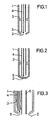
- the invention furthermore relates to a device for introducing molecular oxygen or gases containing it into liquid hydrocarbons, characterized by a tubular jacket 1 with an outlet nozzle 2, and a longitudinally arranged in the jacket by spacers 3 at a distance from the jacket for molecular feeder tube 4 Oxygen or such containing gases with the proviso that the feed pipe 2 ends inside the casing 1 in front of the outlet nozzle 4 and between the end of the feed pipe 4 and the outlet nozzle 2 an element 5 is arranged for temperature measurement.
- the new method and the new device have the advantage that the penetration of hydrocarbons into the oxygen-carrying feed lines can be reliably recognized and the formation of an immersion flame is avoided.
- the inventive method is suitable for example for the oxidation of cycloalkanes to cycloalkyl hydroperoxides or to cycloalkanols and cycloalkanones in the liquid phase for the direct oxidation of propylene to propylene oxide, and for the co-oxidation of hydrocarbons, for. B. for the production of propylene oxide by joint oxidation of propylene and ethylbenzene.
- the process according to the invention is of particular technical importance in the oxidation of cyclohexane, as described, for example, in Swiss Patent 5105,599. is achieved.
- the procedure according to the invention is such that the molecular oxygen supplied or the gas containing molecular oxygen immediately before the point of entry into the liquid hot hydrocarbon, ie. H. at the nozzle opening has a temperature which is at least 20 ° lower than the temperature of the hydrocarbon. If, for example, cyclohexane is oxidized at a temperature of 180 ° C, the molecular oxygen supplied should not exceed a temperature of 160 ° C shortly before the nozzle opening. This is advantageously achieved by avoiding or reducing the heat transfer from the hot reaction mixture to the molecular oxygen to be supplied in the case of supply lines for the molecular oxygen which protrude into the hot reaction mixture.
- the feed line is then expediently automatically flushed with nitrogen or another inert gas. This ensures that there is no uncontrolled reaction in the feed line for the molecular oxygen or the formation of an immersion flame.
- the temperature of the molecular oxygen at the exit point can also advantageously be influenced by the choice of the cross section for the feed line and the flow rate of the molecular oxygen. These parameters can be easily determined by simple preliminary tests.
- a suitable device for carrying out the method is described, for example, in FIG. 1.
- the device consists of a tubular casing 1 with an expediently narrowed outlet nozzle 2 for the media to be introduced.
- a supply pipe 4 for molecular oxygen or gases containing such is arranged at a distance from the casing in the casing by spacers 3.
- the supply pipe 4 ends inside the casing 1 in front of the outlet nozzle 2.
- An element 5 for temperature measurement is arranged between the end of the feed pipe 4 and the outlet nozzle 2.
- a suitable element for temperature measurement is, for example, an NI / CrNi thermocouple.
- the element 5 is expediently supplied for temperature measurement via the feed pipe 4 in order to ensure that the hot reaction medium has as little influence as possible.
- FIG. 2 A further embodiment is shown in FIG. 2, in which 1 designates a tubular casing, 2 an outlet nozzle provided with a frit, 3 spacers, 4 a feed pipe and 5 an element for temperature measurement.
- 1 designates a tubular casing
- 2 an outlet nozzle provided with a frit
- 3 spacers 3 spacers
- 4 a feed pipe
- 5 an element for temperature measurement.
- a variety of nozzles can be used instead of a frit.
- a further embodiment is shown in the two-component nozzle according to FIG. 3, in which 1 a tubular casing, 2 an outlet opening for the media to be introduced, 3 spacers and (4) a feed pipe for molecular oxygen or gases containing such, 5 an element for temperature measurement and 6 mean a supply pipe for hydrocarbons.
Description
- Die Oxidation von Kohlenwasserstoffen, z. B. Cyclohexan mit molekularem Sauerstoff in der Flüssigphase wird bei der Herstellung von Cyclohexanol großtechnisch durchgeführt (vgl. CH-PS 510 599). Hierbei erfolgt die Zuführung des molekularen Sauerstoffs in die Reaktionszone, z. B. über Zweistoffdüsen, Einsteckrohre, Fritten oder ähnliche Einrichtungen. Bei der Durchführung solcher Verfahren muß berücksichtigt werden, daß Sauerstoff mit Kohlenwasserstoffen explosive Gemische bildet. Als besonders gefährlich gilt das Eindringen des zu oxidierenden Kohlenwasserstoffs in die Zufuhrleitung des Sauerstoffs oder Sauerstoff enthaltende Gase. Ebenso ist die Ausbildung einer Tauchflamme gefährlich, da dies zum Schmelzen der Zufuhreinrichtungen führt.
- Um das Eindringen von Kohlenwasserstoffen in die sauerstofführenden Leitungen zu verhindern, werden z. B. Druckdifferenz- oder Durchflußgeräte eingesetzt, die beim Unterschreiten eines Minimaldifferenzdruckes oder einer Minimaldurchflußmenge durch Spülung der Leitungen mit Stickstoff die Zufuhr des Sauerstoffs und somit die Reaktion unterbrechen. Diese Arbeitsweisen sind jedoch störanfällig und haben den Nachteil, daß die Meßstellen zur Druck- und Durchflußmessung nur außerhalb des Reaktionsraumes angebracht werden können, wodurch bei plötzlich auftretenden Undichtigkeiten in den Leitungen zwischen den Meßstellen und dem Reaktionsraum die Druckdifferenz oder Durchflußmengenwerte nicht abfallen und so die Zufuhr des Sauerstoffs nicht unterbrochen wird.
- Entsprechend der DE-OS 2 452 803 soll an der Austrittsstelle des molekularen Sauerstoffs in das Reaktionsmedium ein Thermoelement angeordnet sein, um die Temperatur zu überwachen un beim Entstehen einer Tauchflamme die Sauerstoffzufuhr zu unterbrechen. Diese Arbeitsweise hat sich zum rechtzeitigen Erkennen des Eindringens von Kohlenwasserstoffen in die sauerstoffzuführende Leitung, bevor es zu einer Explosion oder zur Bildung einer Tauchflamme kommt, nicht bewährt. Bei der Zufuhr von Sauerstoff durch das Einsteckrohr erhitzt sich der molekulare Sauerstoff an den heißen Wänden bis fast auf Reaktionstemperatur. Die durch das Thermoelement angezeigte Temperatur ist deshalb nahezu Identisch mit der Reaktortemperatur, so daß sich ein Eindringen von Kohlenwasserstoff in die sauerstofführende Leitung nicht sofort deutlich durch einen Temperaturanstieg bemerkbar macht. Dies gilt ganz besonders bei der Dosierung von molekularem Sauerstoff über den äußeren Ringspalt von Zweistoffdüsen, wenn man gleichzeitig über die Innenbohrung vorgeheizte Kohlenwasserstoffe zuführt. In diesem Fall erwärmt sich der molekulare Sauerstoff sowohl vom äußeren Teil wie auch vom inneren Teil der Zweistoffdüse.
- Es war deshalb die technische Aufgabe gestellt, ein Verfahren und eine Vorrichtung zu entwickeln, die es gestattet, die Zuführung von molekularem Sauerstoff oder solchen enthaltenden Gasen bei der Oxidation von Kohlenwasserstoffen in der flüssigen Phase so zu gestalten, daß bei Eindringen von Kohlenwasserstoffen in die sauerstoffzuführenden Leitungen oder bei der Ausbildung einer Tauchflamme die Oxidation rechtzeitig unterbrochen wird.
- Diese Aufgabe wird gelöst in einem Verfahren zur sicheren Zuführung von molekularem Sauerstoff oder solchen enthaltenden Gasen bei der Oxidation von Kohlenwasserstoffen in flüssiger Phase, dadurch gekennzeichnet, daß der zuführende molekulare Sauerstoff oder das solche enthaltende Gas unmittelbar vor der Stelle des Eintritts in den flüssigen oxidierenden Kohlenwasserstoff eine um mindestens 20 °C niedrigere Temperatur aufweist als die Temperatur des Kohlenwasserstoffs und sobald der zuzuführende molekulare Sauerstoff oder das solchen enthaltende Gas die vorgegebene Temperatur an der Zufuhrstelle überschreitet, die Zufuhr des Sauerstoffs oder des molekularen Sauerstoff enthaltenden Gases unterbrochen wird.
- Ferner ist ein Gegenstand der Erfindung eine Vorrichtung zum Einleiten von molekularen Sauerstoff oder solchen enthaltenden Gasen in flüssige kohlenwasserstoffe, gekennzeichnet durch eine rohrförmige Ummantelung 1 mit einer Austrittsdüse 2, ein in Längsrichtung in der Ummantelung durch Abstandshalter 3 im Abstand von der Ummantelung angeordnete Zuführungsrohr4 für molekularen Sauerstoff oder solchen enthaltende Gase mit der Maßgabe, daß das Zuführungsrohr 2 innerhalb der Ummantelung 1 vor der Austrittsdüse 4 endet und zwischen dem Ende des Zuführungsrohres 4 und der Austrittsdüse 2 ein Element 5 zur Temperaturmessung angeordnet ist.
- Das neue Verfahren und die neue Vorrichtung haben den Vorteil, daß das Eindringen von Kohlenwasserstoffen in die sauerstofführenden Zuführungsleitungen sicher zu erkennen ist und die Ausbildung einer Tauchflamme vermieden wird.
- Das erfindungsgemäße Verfahren eignet sich beispielsweise für die Oxidation von Cycloalkanen zu Cycloalkylhydroperoxiden oder zu Cycloalkanolen und Cycloalkanonen in flüssiger Phase ferner für die Direktoxidation von Propylen zu Propylenoxid, sowie für die Co-oxidation von Kohlenwasserstoffen, z. B. für die Herstellung von Propylenoxid durch gemeinsame Oxidation von Propylen und Äthylbenzol. Besondere technische Bedeutung hat das erfindungsgemäße Verfahren bei der Oxidation von Cyclohexan wie es beispielsweise in der CH-PS 5105 599 beschrieben . ist, erlangt. In der Regel wird die Oxidation von Cyclohexan bei Temperaturen von 140 bis 200 °C unter Drücken von 10 bis 60 bar gegebenenfalls unter Mitverwendung von Katalysatoren, wie Kobaltsalze, durch Einleiten von molekularem Sauerstoff oder solchen enthaltenden Gasen in das flüssige Reaktionsgemisch durchgeführt.
- Erfindungsgemäß verfährt man so, daß der zugeführte molekulare Sauerstoff oder das molekularen Sauerstoff enthaltende Gas unmittelbar vor der Stelle des Eintritts in den flüssigen heißen Kohlenwasserstoff, d. h. an der Düsenöffnung eine um mindestens um 20° niedrigere Temperatur aufweist als die Temperatur des Kohlenwasserstoffs. Wird beispielsweise Cyclohexan bei einer Temperatur von 180 °C oxidiert, so soll der zugeführte molekulare Sauerstoff kurz vor der Düsenöffnung eine Temperatur von 160 °C nicht überschreiten. Dies erreicht man vorteilhaft, indem man bei Zuführungsleitungen für den molekularen Sauerstoff, die in das heiße Reaktionsgemisch hineinragen, die Wärmeübertragung vom heißen Reaktionsgemisch auf den zuzuführenden molekularen Sauerstoff vermeidet oder vermindert. Besonders bewährt hat es sich, die in das heiße Reaktionsgemisch hineinragende Zuführungsleitung für molekularen Sauerstoff durch eine isolierende Gasschicht zu umgeben. Dies erreicht man auf einfache Weise, indem man die in das heiße Reaktionsgemisch hineinragende Zuführungsleitung für molekularen Sauerstoff mit einem weiteren Rohr umgibt, dessen Austrittsende etwas eingeengt sein kann mit der Maßgabe, daß Zuführungsleitung für den molekularen Sauerstoff vorher endet. Hierdurch ergibt sich bei Zuführen von Sauerstoff eine Gasschicht, die isolierend wirkt. Im Zwischenraum zwischen dem Austritt des molekularen Sauerstoffs aus der Zuführungsleitung und der Öffnung der Ummantelung wird die Temperatur des molekularen Sauerstoffs gemessen. Sobald der zuzuführende molekulare Sauerstoff die vorgegebene Temperaturen der Austrittsöffnung überschreitet, wird die Zufuhr des molekularen Sauerstoffs oder des molekularen Sauerstoff enthaltenden Gases unterbrochen. Zweckmäßig wird die Zuführungsleitung dann sofort automatisch mit Stickstoff oder einem anderen in Inertgas gespült. Auf diese Weise ist sichergestellt, daß keine unkontrollierte Reaktion in der Zuführungsleitung für den molekularen Sauerstoff oder die Ausbildung einer Tauchflamme eintritt. Vorteilhaft läßt sich die Temperatur des molekularen Sauerstoffs an der Austrittsstelle auch noch durch die Wahl des Querschnitts für die Zuführungsleitung und Strömungsgeschwindigkeit des molekularen Sauerstoffs beeinflussen. Diese Parameter sind durch einfache Vorversuche leicht zu ermitteln.
- Eine geeignete Vorrichtung zur Durchführung des Verfahrens wird peispielsweise in. Fig. 1 beschrieben. Die Vorrichtung besteht aus einer rohrförmigen Ummantelung 1 mit einer zweckmäßig verengten Austrittsdüse 2 für die einzuleitenden Medien. In Längsrichtung ist in der Ummantelung durch Abstandshalter 3 ein Zuführungsrohr 4 für molekularen Sauerstoff oder solche enthaltende Gase im Abstand von der Ummantelung angeordnet. Das Zuführungsrohr 4 endet innerhalb der Ummantelung 1 vor der Austrittsdüse 2. Hierdurch wird beim Einleiten von Sauerstoff durch das Zuführungsrohr 4 der Zwischenraum zwischen dem Zuführungsrohr 4 und der Ummantelung 1 von selbst mit Sauerstoff gefüllt und es bildet sich eine isolierende Gasschicht aus. Zwischen dem Ende des Zuführungsrohres 4 und der Austrittsdüse 2 ist ein Element 5 zur Temperaturmessung angeordnet. Ein geeignetes Element zur Temperaturmessung ist beispielsweise ein NI/CrNi-Thermoelement. Zweckmäßig führt man das Element 5 zur Temperaturmessung über das Zuführungsrohr 4 zu, um eine möglichst geringe Beeinflussung durch das heiße Reaktionsmedium zu gewährleisten.
- Eine weitere Ausgestaltung wird in Fig. 2 gezeigt, in der 1 eine rohrförmige Ummantelung, 2 eine mit einer Fritte versehene Austrittsdüse, 3 Abstandshalter, 4 ein Zuführungsrohr und 5 ein Element zur Temperaturmessung bezeichnen. Anstatt einer Fritte können auch eine Vielzahl von Düsen verwendet werden.
- Eine weitere Ausführungsform wird in der Zweistoffdüse gemäß Fig. 3 gezeigt, in der 1 eine rohrförmige Ummantelung, 2 eine Austrittsöffnung für die einzuleitenden Medien, 3 Abstandshalter und (4) ein Zuführungsrohr für molekularen Sauerstoff oder solchen enthaltende Gase, 5 ein Element zur Temperaturmessung und 6 ein Zuführungsrohr für Kohlenwasserstoffe bedeuten.
Claims (5)
Applications Claiming Priority (2)
| Application Number | Priority Date | Filing Date | Title |
|---|---|---|---|
| DE3001880 | 1980-01-19 | ||
| DE19803001880 DE3001880A1 (de) | 1980-01-19 | 1980-01-19 | Verfahren zur sicheren zufuehrung von molekularem sauerstoff oder solchen enthaltenden gasen bei der oxidation von kohlenwasserstoffen |
Publications (2)
| Publication Number | Publication Date |
|---|---|
| EP0033084A1 EP0033084A1 (de) | 1981-08-05 |
| EP0033084B1 true EP0033084B1 (de) | 1983-02-16 |
Family
ID=6092467
Family Applications (1)
| Application Number | Title | Priority Date | Filing Date |
|---|---|---|---|
| EP81100190A Expired EP0033084B1 (de) | 1980-01-19 | 1981-01-13 | Verfahren und Vorrichtung zum sicheren Zuführen von molekularem Sauerstoff oder solchen enthaltenden Gasen bei der Oxidation von Kohlenwasserstoffen |
Country Status (4)
| Country | Link |
|---|---|
| US (1) | US4491674A (de) |
| EP (1) | EP0033084B1 (de) |
| JP (1) | JPS56118020A (de) |
| DE (2) | DE3001880A1 (de) |
Families Citing this family (5)
| Publication number | Priority date | Publication date | Assignee | Title |
|---|---|---|---|---|
| DE3328771A1 (de) * | 1983-08-10 | 1985-02-28 | Basf Ag, 6700 Ludwigshafen | Verfahren zur kontinuierlichen herstellung von sauerstoff enthaltenden verbindungen |
| US5068464A (en) * | 1988-05-26 | 1991-11-26 | Basf Corporation | Process for the oxidation of hydrocarbons utilizing partitioning of oxidizing gas |
| ID19133A (id) * | 1996-12-12 | 1998-06-18 | Praxair Technology Inc | Pengisian oksigen langsung kedalam reaktor-reaktor ruang gelembung |
| EA200700028A1 (ru) * | 2003-11-14 | 2007-08-31 | Александр Васильевич Пугачев | Способ и реактор для конвертирования углеводородов каскадным окислительным крекингом |
| JP2008280328A (ja) * | 2007-04-13 | 2008-11-20 | Sumitomo Chemical Co Ltd | シクロアルカノール及び/又はシクロアルカノンの製造方法 |
Citations (3)
| Publication number | Priority date | Publication date | Assignee | Title |
|---|---|---|---|---|
| GB977064A (en) * | 1961-04-19 | 1964-12-02 | Halcon International Inc | Improvements in the oxidation or cyclohexane to produce partial oxidation products thereof |
| DE1914448A1 (de) * | 1968-03-23 | 1969-11-13 | Stamicarbon | Verfahren zum Oxydieren von Zyklohexan,zu Zyklohexanon und/oder Zyklohexanol |
| CH510599A (de) * | 1967-07-26 | 1971-07-31 | Inventa Ag | Kontinuierliches Verfahren zur Herstellung eines Cyclohexanol/Cyclohexanon-Gemisches aus Cyclohexan |
Family Cites Families (4)
| Publication number | Priority date | Publication date | Assignee | Title |
|---|---|---|---|---|
| US2009663A (en) * | 1932-08-01 | 1935-07-30 | Clarence P Byrnes | Manufacture of oxygen derivatives of hydrocarbons |
| US3006944A (en) * | 1960-02-24 | 1961-10-31 | Exxon Research Engineering Co | High temperature oxidation |
| US3170863A (en) * | 1960-09-30 | 1965-02-23 | Monsanto Co | Hydrocarbon conversion process |
| DE2452803A1 (de) * | 1974-11-07 | 1976-05-20 | Basf Ag | Vorrichtung fuer die oxidation von kohlenwasserstoffen |
-
1980
- 1980-01-19 DE DE19803001880 patent/DE3001880A1/de not_active Withdrawn
- 1980-12-08 US US06/213,793 patent/US4491674A/en not_active Expired - Lifetime
-
1981
- 1981-01-13 EP EP81100190A patent/EP0033084B1/de not_active Expired
- 1981-01-13 DE DE8181100190T patent/DE3160061D1/de not_active Expired
- 1981-01-14 JP JP330181A patent/JPS56118020A/ja active Granted
Patent Citations (3)
| Publication number | Priority date | Publication date | Assignee | Title |
|---|---|---|---|---|
| GB977064A (en) * | 1961-04-19 | 1964-12-02 | Halcon International Inc | Improvements in the oxidation or cyclohexane to produce partial oxidation products thereof |
| CH510599A (de) * | 1967-07-26 | 1971-07-31 | Inventa Ag | Kontinuierliches Verfahren zur Herstellung eines Cyclohexanol/Cyclohexanon-Gemisches aus Cyclohexan |
| DE1914448A1 (de) * | 1968-03-23 | 1969-11-13 | Stamicarbon | Verfahren zum Oxydieren von Zyklohexan,zu Zyklohexanon und/oder Zyklohexanol |
Also Published As
| Publication number | Publication date |
|---|---|
| DE3160061D1 (en) | 1983-03-24 |
| US4491674A (en) | 1985-01-01 |
| EP0033084A1 (de) | 1981-08-05 |
| DE3001880A1 (de) | 1981-07-23 |
| JPH0226608B2 (de) | 1990-06-12 |
| JPS56118020A (en) | 1981-09-16 |
Similar Documents
| Publication | Publication Date | Title |
|---|---|---|
| EP1288182B1 (de) | Verfahren zur direkten methanpyrolyse | |
| EP0095103B1 (de) | Verfahren und Vorrichtung zur Herstellung von Synthesegas durch partielle Oxidation von Kohle-Wasser-Suspensionen | |
| EP0157758A2 (de) | Verfahren zur Herstellung von Synthesegasen, insbesondere Reduktionsgasen, sowie Vorrichtung zur Durchführung des Verfahrens | |
| CH414565A (de) | Verfahren und Vorrichtung zur Durchführung chemischer Reaktionen mit einer Schmelze als wärmeübertragendes Medium | |
| DE2107960A1 (de) | Verfahren und Vorrichtung zum Vermischen eines Gases und einer Flüssigkeit | |
| WO2010063448A1 (de) | Vorrichtung und verfahren für katalytische gasphasenreaktionen sowie deren verwendung | |
| EP0033084B1 (de) | Verfahren und Vorrichtung zum sicheren Zuführen von molekularem Sauerstoff oder solchen enthaltenden Gasen bei der Oxidation von Kohlenwasserstoffen | |
| EP0724010A1 (de) | Verfahren und Vorrichtung zum Ableiten eines Heissen, Kohlenmonoxid enthaltenden Gasgemisches | |
| DE1443435A1 (de) | Kontinuierliches Verfahren zu Oxydation aromatischer Verbindungen mit Salpetersaeure | |
| EP3368473B1 (de) | Vorrichtung und verfahren zum erzeugen von synthesegas | |
| DE2017694C3 (de) | Vorrichtung zur Verhinderung des vorzeitigen Verschleißes von Konverter boden | |
| DE2127397A1 (de) | Verfahren und Vorrichtung zur Gewinnung von Schwefel aus einem Schwefelwasserstoffenthaltenden sauren Gas | |
| DE1592317B2 (de) | Vorrichtung zur katalytischen spaltung von kohlenwasserstoffen unter bildung eines wasserstoff/kohlenmonoxid-gemisches | |
| DE2834737A1 (de) | Stahlherstellungsverfahren | |
| WO2015028539A1 (de) | Vorrichtung und verfahren zum herstellen von acetylen und synthesegas | |
| CH374646A (de) | Verfahren und Vorrichtung zur Herstellung von Acetylen durch partielle Oxydation von Kohlenwasserstoffen | |
| DE3130972A1 (de) | "verfahren zum vorwaermen und aufheizen von leeren aod-konvertern" | |
| DE889241C (de) | Verfahren und Vorrichtung zur Erzeugung grosser Mengen Gase von hohem Druck durch Verbrennung | |
| DE1758816C2 (de) | Verfahren zum Frischen von Roheisen zu Stahl | |
| DE2508284C3 (de) | Verfahren zur Polymerisation von Äthylen | |
| DE3403987A1 (de) | Verfahren zur herstellung von halbsynthetischen schutz- und reaktionsgasen, insbesondere zur waermebehandlung von stahl- und metallwerkstoffen, bestehend aus einer mischung unterschiedlich waehlbarer mengen von stickstoff, wasserstoff, kohlenmonoxyd, kohlendioxyd sowie wasserdampf | |
| DE918933C (de) | Verfahren zur Herstellung eines brennbaren Blankgluehgases | |
| DE2261562C3 (de) | Verfahren zur Herstellung von Vinylacetat | |
| AT391311B (de) | Verfahren zur herstellung von pruefgasgemischen mit stickstoffoxiden und vorrichtung zur durchfuehrungeines solchen verfahrens | |
| DE2432213A1 (de) | Verfahren zum kracken von rohoel |
Legal Events
| Date | Code | Title | Description |
|---|---|---|---|
| PUAI | Public reference made under article 153(3) epc to a published international application that has entered the european phase |
Free format text: ORIGINAL CODE: 0009012 |
|
| AK | Designated contracting states |
Designated state(s): BE CH DE FR GB IT NL |
|
| 17P | Request for examination filed |
Effective date: 19810808 |
|
| ITF | It: translation for a ep patent filed |
Owner name: ING. C. GREGORJ S.P.A. |
|
| GRAA | (expected) grant |
Free format text: ORIGINAL CODE: 0009210 |
|
| AK | Designated contracting states |
Designated state(s): BE CH DE FR GB IT LI NL |
|
| REF | Corresponds to: |
Ref document number: 3160061 Country of ref document: DE Date of ref document: 19830324 |
|
| ET | Fr: translation filed | ||
| ITTA | It: last paid annual fee | ||
| PGFP | Annual fee paid to national office [announced via postgrant information from national office to epo] |
Ref country code: FR Payment date: 19991215 Year of fee payment: 20 |
|
| PGFP | Annual fee paid to national office [announced via postgrant information from national office to epo] |
Ref country code: NL Payment date: 19991220 Year of fee payment: 20 |
|
| PGFP | Annual fee paid to national office [announced via postgrant information from national office to epo] |
Ref country code: DE Payment date: 19991223 Year of fee payment: 20 Ref country code: CH Payment date: 19991223 Year of fee payment: 20 |
|
| PGFP | Annual fee paid to national office [announced via postgrant information from national office to epo] |
Ref country code: GB Payment date: 20000105 Year of fee payment: 20 |
|
| PGFP | Annual fee paid to national office [announced via postgrant information from national office to epo] |
Ref country code: BE Payment date: 20000125 Year of fee payment: 20 |
|
| BE20 | Be: patent expired |
Free format text: 20010113 *BASF A.G. |
|
| PG25 | Lapsed in a contracting state [announced via postgrant information from national office to epo] |
Ref country code: LI Free format text: LAPSE BECAUSE OF EXPIRATION OF PROTECTION Effective date: 20010112 Ref country code: GB Free format text: LAPSE BECAUSE OF EXPIRATION OF PROTECTION Effective date: 20010112 Ref country code: CH Free format text: LAPSE BECAUSE OF EXPIRATION OF PROTECTION Effective date: 20010112 |
|
| PG25 | Lapsed in a contracting state [announced via postgrant information from national office to epo] |
Ref country code: NL Free format text: LAPSE BECAUSE OF EXPIRATION OF PROTECTION Effective date: 20010113 |
|
| REG | Reference to a national code |
Ref country code: CH Ref legal event code: PL |
|
| REG | Reference to a national code |
Ref country code: GB Ref legal event code: PE20 Effective date: 20010112 |
|
| NLV7 | Nl: ceased due to reaching the maximum lifetime of a patent |
Effective date: 20010113 |
|
| PLBE | No opposition filed within time limit |
Free format text: ORIGINAL CODE: 0009261 |
|
| STAA | Information on the status of an ep patent application or granted ep patent |
Free format text: STATUS: NO OPPOSITION FILED WITHIN TIME LIMIT |