EP0031873B1 - Motorische Antriebseinheit und deren Verwendung - Google Patents
Motorische Antriebseinheit und deren Verwendung Download PDFInfo
- Publication number
- EP0031873B1 EP0031873B1 EP19800105885 EP80105885A EP0031873B1 EP 0031873 B1 EP0031873 B1 EP 0031873B1 EP 19800105885 EP19800105885 EP 19800105885 EP 80105885 A EP80105885 A EP 80105885A EP 0031873 B1 EP0031873 B1 EP 0031873B1
- Authority
- EP
- European Patent Office
- Prior art keywords
- motor
- worm wheel
- worm
- transmission
- drive
- Prior art date
- Legal status (The legal status is an assumption and is not a legal conclusion. Google has not performed a legal analysis and makes no representation as to the accuracy of the status listed.)
- Expired
Links
- 230000005540 biological transmission Effects 0.000 title claims 14
- 230000008878 coupling Effects 0.000 description 2
- 238000010168 coupling process Methods 0.000 description 2
- 238000005859 coupling reaction Methods 0.000 description 2
- 230000001133 acceleration Effects 0.000 description 1
- 230000001419 dependent effect Effects 0.000 description 1
- 238000006073 displacement reaction Methods 0.000 description 1
- 230000002349 favourable effect Effects 0.000 description 1
- 230000002093 peripheral effect Effects 0.000 description 1
- 230000033764 rhythmic process Effects 0.000 description 1
Images
Classifications
-
- F—MECHANICAL ENGINEERING; LIGHTING; HEATING; WEAPONS; BLASTING
- F16—ENGINEERING ELEMENTS AND UNITS; GENERAL MEASURES FOR PRODUCING AND MAINTAINING EFFECTIVE FUNCTIONING OF MACHINES OR INSTALLATIONS; THERMAL INSULATION IN GENERAL
- F16H—GEARING
- F16H1/00—Toothed gearings for conveying rotary motion
- F16H1/02—Toothed gearings for conveying rotary motion without gears having orbital motion
- F16H1/04—Toothed gearings for conveying rotary motion without gears having orbital motion involving only two intermeshing members
- F16H1/12—Toothed gearings for conveying rotary motion without gears having orbital motion involving only two intermeshing members with non-parallel axes
- F16H1/16—Toothed gearings for conveying rotary motion without gears having orbital motion involving only two intermeshing members with non-parallel axes comprising worm and worm-wheel
Definitions
- the present invention relates to a motor drive unit for machines, with a worm wheel that can be rotatably connected to the machine shaft, into which a worm shaft engages, on which a drive motor that overcomes the load torque on the worm wheel engages.
- machines with controllable or controllable motor drives are used to let the machines work in changing rhythms or to enable the machines to be adapted to rapidly changing operating conditions.
- DC motors are, however, comparatively expensive, especially in higher kW ranges.
- this is achieved in the motor drive unit in that another worm shaft, which is driven by a control motor and serves to change the speed of the drive unit, engages with the worm wheel and forms a self-locking gear with the worm wheel.
- the necessary circumferential force on the worm wheel is applied by the drive motor.
- the circumferential force is understood to mean the positive difference between the torque on the drive motor and the counteracting load torque on the worm wheel. If this difference goes to zero, which can be achieved, for example, by means of proportional control on the drive motor, the required torque on the controlling DC motor also goes to zero, which results in no-power control of the motor drive unit.
- Such a drive unit also has a comparatively small volume and a low weight.
- GB-A-No. 260566 already shows a self-locking worm gear on a gear arrangement for moving a load, but in which arrangement the self-locking gear acts on the shaft of the drive motor, which serves to adjust a load via a step gear.
- the self-locking gear acts as a locking device and only allows the load to be adjusted if the worm shaft is rotated by motor or by hand, which should enable the finest angle adjustments on the load.
- motor drive unit An expedient embodiment of the motor drive unit can also be seen in the fact that the worm wheel and thus the entire drive unit can be plugged onto a load shaft.
- the use of the motor drive unit to form a multiple drive with at least two such drive units is advantageous, in which case the drive motors in the form of hydraulic motors of all drive units of the multiple drive are connected to a common supply unit.
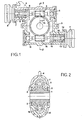
- the example embodiment of a motor drive unit according to FIGS. 1 and 2 comprises a worm wheel 1 which is designed to be plugged onto a machine drive shaft, not shown in any more detail.
- this worm wheel 1 is supported on a housing 3 via bearing means 2 (FIG. 2).
- a torque support 4 protrudes from this housing 3.
- a first worm shaft 5 meshes with the worm wheel 1, which is also supported on the housing 3 via bearing means 6.
- This worm shaft 5 projects on one side into the area of a housing flange 7 to which a DC motor 8 is flanged, the shaft 9 of this motor 8 and the worm shaft 5 being connected to one another by an elastic coupling 10.
- the central pitch angle m (FIG. 1) between the worm wheel 1 and the control worm shaft 5 corresponds to the angle of friction thereof.
- this arrangement behaves like a self-locking screw in a carrier, the pitch angle of the screw corresponding to the load-dependent friction angle screw-carrier, and loads of any size can be reduced by turning the screw with a required torque towards zero.
- the worm shaft 5 corresponds to the screw, the worm shaft 5 receiving the rotation from the DC motor 8.
- the load that can be moved is the circumferential force on the worm wheel 1, which represents the positive difference between a driving force acting on the worm wheel 1 and the counteracting operating load, here on the machine shaft.
- the driving force on the worm wheel 1 is controlled so that the peripheral force remains as small as possible, the required torque on the controlling DC motor 8 goes to zero.
- the DC motor 8 can thus be very small. It has been shown that conventional and inexpensive universal motors are sufficient for this, the control or regulation of these motors being able to take place as before or to be simplified, since the control is now carried out practically without power.
- Said driving force can of course be applied to the worm wheel as desired. Different forms of energy can also be used for this.
- the driving force is applied by a hydraulic motor 11 which is flanged to a further flange 12 of the housing 3.
- the shaft 13 of this hydraulic motor 11 is connected via a coupling 14 to a further worm shaft 15, which is supported on the housing 3 via bearing means 16 and which also meshes with the worm wheel 1 as a drive worm shaft.
- Motorized drive units according to the invention and as described above can in particular also be used for multiple drives.
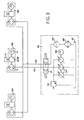
- Such a multiple drive is illustrated in FIG. 3.
- three motor drive units 20 are provided, each of which the worm gear 1, 5, 15; include the DC motor 8 and the hydraulic motor 11.
- Each drive unit 20 drives a roller 21.
- All hydraulic motors 11 of the drive units 20 are connected here to a common supply unit 30 via feed lines 22 and return lines 23.
- This supply unit 30 includes u. a. Directional spool valve 31, a pressure relief valve 32, variable displacement pumps 34 operated by a motor 33 and an oil filter 35, an oil cooler 36 and the tank 37.
Landscapes
- Engineering & Computer Science (AREA)
- General Engineering & Computer Science (AREA)
- Mechanical Engineering (AREA)
- Gear Transmission (AREA)
Description
- Die vorliegende Erfindung betrifft eine motorische Antriebseinheit für Maschinen, mit einem, mit der Maschinenwelle drehverbindbaren Schneckenrad, in das eine Schneckenwelle eingreift, an der ein das Lastmoment am Schnekkenrad überwindender Antriebsmotor angreift.
- In vielen Bereichen der Industrie werden Maschinen mit steuerbaren bzw. regelbaren Motorantrieben verwendet, um die Maschinen in wechselnden Rhythmen arbeiten zu lassen bzw. die Anpassung der Maschinen an rasch wechselnde Betriebsbedingungen zu ermöglichen.
- Mehrheitlich werden hierfür Gleichstrom-Motoren verwendet, da diese relativ leicht steuerbar sind.
- Gleichstrom-Motoren sind aber, insbesondere in höheren kW- Bereichen, vergleichsweise teuer.
- Es ist nun Aufgabe der vorliegenden Erfindung, eine motorische Antriebseinheit für Maschinen zu schaffen, die bei vergleichsweiser Leistung und Steuerbarkeit eines GleichstromMotors wesentlich kostengünstiger und zudem noch universeller anwendbar ist.
- Dies wird bei der motorischen Antriebseinheit erfindungsgemäss dadurch erreicht, dass mit dem Schneckenrad eine weitere, von einem Steuermotor angetriebene, der Drehzahländerung an der Antriebseinheit dienende Schnekkenwelle in Eingriff steht, die mit dem Schnekkenrad ein selbsthemmendes Getriebe bildet.
- Durch diese Massnahmen und insbesondere durch die Selbsthemmung am steuernden Schneckengetriebe ist es nunmehr möglich, an der motorischen Antriebseinheit einen relativ kleinen und billigen Gleichstrom-Motor, etwa einen sogenannten Universalmotor vorzusehen, da dieser nur noch die in der Praxis verbleibende Reibung sowie geringe Beschleunigungen überwinden muss; die notwendige Umfangskraft am Schneckenrad aber vom Antriebsmotor aufgebracht wird. Hierbei wird unter der Umfangskraft die positive Differenz zwischen dem Drehmoment am Antriebsmotor und dem entgegenwirkenden Last-Drehmoment am Schneckenrad verstanden. Geht diese Differenz gegen Null, was sich beispielsweise durch Proportionalregelung am Antriebsmotor erreichen lässt, so geht auch das erforderliche Drehmoment am steuernden Gleichstrom-Motor gegen Null, womit eine leistungslose Regelung der motorischen Antriebseinheit erreicht wird.
- Eine solche Antriebseinheit weist zudem vergleichsweise ein geringes Volumen und ein geringes Gewicht auf.
- Zwar zeigt die GB-A- Nr. 260566 schon ein selbsthemmendes Schneckengetriebe an einer Getriebeanordnung zur Bewegung einer Last, bei welcher Anordnung aber das selbsthemmende Getriebe an der Welle des Antriebsmotors angreift, der über ein Stufengetriebe dem Verstellen einer Last dient. Hierbei wirkt das selbsthemmende Getriebe als Sperrvorrichtung und gestattet ein Verstellen der Last nur, wenn die Schneckenwelle motorisch oder von Hand verdreht wird, womit feinste Winkelverstellungen an der Last ermöglicht werden sollen.
- Eine zweckmässige Ausgestaltung der motorischen Antriebseinheit kann weiter darin gesehen werden, dass das Schneckenrad und somit die ganze Antriebseinheit auf eine Lastwelle aufsteckbar ist.
- Dies erlaubt, die motorische Antriebseinheit direkt auf eine Maschinen-Antriebswelle aufzusetzen ohne Verwendung von Zwischengetrieben, was besonders für Walzenanordnungen mit veränderlichem Abstand vorteilhaft ist.
- Ferner ist die Verwendung der motorischen Antriebseinheit zur Bildung eines Mehrfachantriebes mit mindestens zwei solcher Antriebseinheiten vorteilhaft, wobei dann die Antriebsmotoren in Form von Hydromotoren aller Antriebseinheiten des Mehrfachantriebes an einer gemeinsamen Versorgungseinheit angeschlossen sind.
- Beispielsweise Ausführungsformen des Erfindungsgegenstandes werden nachfolgend anhand der Zeichnung näher erläutert. Es zeigen:
- Fig. 1 eine Schnittansicht einer erfindungsgemässen motorischen Antriebseinheit;
- Fig. 2 eine Schnittansicht entlang der Schnittlinie II - in Fig. 1; und
- Fig. 3 eine schematische Darstellung eines Mehrfachantriebes mit drei Antriebseinheiten und einer gemeinsamen Versorgungseinheit für die Hydromotoren der Antriebseinheiten.
- Die beispielsweise Ausführungsform einer motorischen Antriebseinheit gemäss den Figuren 1 und 2 umfasst ein Schneckenrad 1, welches aufsteckbar auf eine nicht näher gezeigte Maschinen-Antriebswelle ausgebildet ist. Hierfür stützt sich dieses Schneckenrad 1 über Lagermittel 2 an einem Gehäuse 3 ab (Fig. 2). Von diesem Gehäuse 3 ragt eine Drehmomentabstützung 4 ab.
- Mit dem Schneckenrad 1 kämmt eine erste Schneckenwelle 5, welche sich ebenfalls über Lagermittel 6 am Gehäuse 3 abstützt. Diese Schneckenwelle 5 ragt einseitig in den Bereich eines Gehäuseflansches 7, an welchem ein Gleichstrom-Motor 8 angeflanscht ist, wobei die Welle 9 dieses Motors 8 und die Schneckenwelle 5 durch eine elastische Kupplung 10 miteinander verbunden sind.
- Ein erfindungswesentliches Merkmal dieser vorbeschriebenen Anordnung ist nun, dass der Mittensteigungswinkel m (Fig. 1) zwischen dem Schneckenrad 1 und der Steuer-Schneckenwelle 5 deren Reibungswinkel entspricht. Mit anderen Worten verhält sich diese Anordnung wie eine selbsthemmende Schraube in einem Träger, wobei der Steigungswinkel der Schraube dem lastabhängigen Reibungswinkel Schraube-Träger entspricht und wobei durch Drehen an der Schraube beliebig grosse Lasten absenkbar sind mit einem erforderlichen Drehmoment gegen Null. Vergleichsweise hierzu entspricht die Schneckenwelle 5 der Schraube, wobei die Schneckenwelle 5 vom Gleichstrom-Motor 8 die Drehung erhält. Die damit bewegbare Last ist die Umfangskraft am Schneckenrad 1, welche die positive Differenz zwischen einer am Schnekkenrad 1 angreifenden Antriebskraft und der entgegenwirkenden Betriebslast, hier an der Maschinenwelle, darstellt. Wird hierbei die Antriebskraft am Schneckenrad 1 so gesteuert, dass die Umfangskraft möglichst klein bleibt, geht das erforderliche Drehmoment am steuernden Gleichstrom-Motor 8 gegen Null. Der Gleichstrom-Motor 8 kann somit sehr klein sein. Es hat sich gezeigt, dass hierfür übliche und kostengünstige Universalmotoren genügen, wobei die Steuerung bzw. Regelung dieser Motoren wie bisher erfolgen kann oder auch eine Vereinfachung erfahren kann, da die Steuerung nun praktisch leistungslos erfolgt.
- Die genannte Antriebskraft kann natürlich beliebig auf das Schneckenrad aufgebracht werden. Ferner können hierfür unterschiedliche Energieformen zur Anwendung gelangen.
- Beim Ausführungsbeispiel gemäss den Figuren 1 und 2 wird die Antriebskraft von einem Hydromotor 11 aufgebracht, der an einem weiteren Flansch 12 des Gehäuses 3 angeflanscht ist. Die Welle 13 dieses Hydromotors 11 ist über eine Kupplung 14 mit einer weiteren Schneckenwelle 15 verbunden, die sich über Lagermittel 16 am Gehäuse 3 abstützt und die als Antriebs-Schneckenwelle ebenfalls das Schneckenrad 1 kämmt.
- Aus dem Vorbeschriebenen ergibt sich somit eine kompakte, einfach konzipierte und somit sehr kostengünstige motorische Antriebseinheit mit einem grossen Anwendungsbereich.
- Motorische Antriebseinheiten gemäss der Erfindung und wie vorbeschrieben lassen sich insbesondere auch für Mehrfachantriebe verwenden.
- Ein solcher Mehrfachantrieb ist in Fig. 3 veranschaulicht. Bei diesem Mehrfachantrieb sind drei motorische Antriebseinheiten 20 vorgesehen, welche je das Schneckengetriebe 1, 5, 15; den Gleichstrom-Motor 8 und den Hydromotor 11 umfassen. Jede Antriebseinheit 20 treibt eine Walze 21 an.
- Alle Hydromotoren 11 der Antriebseinheiten 20 sind hier über Vorleitungen 22 und Rückleitungen 23 an einer gemeinsamen Versorgungseinheit 30 angeschlossen.
- Diese Versorgungseinheit 30 umfasst u. a. Wegeschieber 31, ein Druckbegrenzungsventil 32, von einem Motor 33 betriebene Verstellpumpen 34 sowie einen Ölfilter 35, einen Ölkühler 36 und den Tank 37.
- Es ist leicht erkennbar, dass ein solcher Mehrfachantrieb eine besonders günstige Anwendung der erfindungsgemässen motorischen Antriebseinheit erlaubt.
Claims (8)
Applications Claiming Priority (2)
| Application Number | Priority Date | Filing Date | Title |
|---|---|---|---|
| CH9093/79 | 1979-10-09 | ||
| CH909379A CH642725A5 (de) | 1979-10-09 | 1979-10-09 | Motorische antriebsvorrichtung fuer maschinen. |
Publications (3)
| Publication Number | Publication Date |
|---|---|
| EP0031873A2 EP0031873A2 (de) | 1981-07-15 |
| EP0031873A3 EP0031873A3 (en) | 1981-07-22 |
| EP0031873B1 true EP0031873B1 (de) | 1984-02-15 |
Family
ID=4348243
Family Applications (1)
| Application Number | Title | Priority Date | Filing Date |
|---|---|---|---|
| EP19800105885 Expired EP0031873B1 (de) | 1979-10-09 | 1980-09-29 | Motorische Antriebseinheit und deren Verwendung |
Country Status (3)
| Country | Link |
|---|---|
| EP (1) | EP0031873B1 (de) |
| CH (1) | CH642725A5 (de) |
| DE (1) | DE3066616D1 (de) |
Cited By (1)
| Publication number | Priority date | Publication date | Assignee | Title |
|---|---|---|---|---|
| DE4140549A1 (de) * | 1991-12-09 | 1993-06-17 | Krupp Polysius Ag | Walzenmuehle |
Families Citing this family (3)
| Publication number | Priority date | Publication date | Assignee | Title |
|---|---|---|---|---|
| DE9311316U1 (de) | 1993-06-19 | 1993-10-14 | IMO - Industrie Momentenlager Stoll & Russ GmbH, 91350 Gremsdorf | Anordnung zum Drehantrieb eines Maschinen- und Anlagenteiles und Schneckengetriebe |
| US5834662A (en) * | 1993-06-19 | 1998-11-10 | Imo-Industrie-Momentenlager Stoll & Russ Gmbh | Arrangement for the rotary actuation of an apparatus on a chassis or foundation |
| AU7211998A (en) * | 1997-11-06 | 1999-05-31 | Imo Industrie-Antriebseinheit Stoll & Russ Gmbh | Rotating drive unit with an overload cut-out |
Family Cites Families (6)
| Publication number | Priority date | Publication date | Assignee | Title |
|---|---|---|---|---|
| US1556033A (en) * | 1922-03-08 | 1925-10-06 | Universal Engineering Corp | Hydraulic mechanism |
| CH113791A (de) * | 1924-09-30 | 1926-02-16 | Jakob Niederhauser | Schneckengetriebe. |
| GB260566A (en) * | 1925-11-02 | 1927-09-01 | Rheinische Metallw & Maschf | Improvements in power transmitting gearing |
| DE883380C (de) * | 1951-03-15 | 1953-07-16 | Siemens Ag | Schneckengetriebe |
| CA1000074A (en) * | 1973-01-09 | 1976-11-23 | Ker-Train Systems Limited | Worm/worm-wheel overrunning clutch |
| FR2251233A5 (en) * | 1973-11-14 | 1975-06-06 | Durand Francois | Reduction gear for e.g. steel mill rollers - transmits increased power by using two worms to drive output wheel |
-
1979
- 1979-10-09 CH CH909379A patent/CH642725A5/de not_active IP Right Cessation
-
1980
- 1980-09-29 DE DE8080105885T patent/DE3066616D1/de not_active Expired
- 1980-09-29 EP EP19800105885 patent/EP0031873B1/de not_active Expired
Cited By (1)
| Publication number | Priority date | Publication date | Assignee | Title |
|---|---|---|---|---|
| DE4140549A1 (de) * | 1991-12-09 | 1993-06-17 | Krupp Polysius Ag | Walzenmuehle |
Also Published As
| Publication number | Publication date |
|---|---|
| CH642725A5 (de) | 1984-04-30 |
| EP0031873A3 (en) | 1981-07-22 |
| DE3066616D1 (en) | 1984-03-22 |
| EP0031873A2 (de) | 1981-07-15 |
Similar Documents
| Publication | Publication Date | Title |
|---|---|---|
| EP0329741B1 (de) | Stufenlos regelbarer antrieb | |
| EP0615077A1 (de) | Antrieb mit zwei Hydromotoren | |
| EP0386201B1 (de) | Stufenlos regelbarer antrieb | |
| DE69014073T2 (de) | Verbesserung an einem Antriebsgetriebe. | |
| EP0383915A1 (de) | Elektrischer antrieb mit zusätzlichem handantrieb | |
| DE2302518A1 (de) | Geschwindigkeitswechselgetriebe | |
| DE683913C (de) | Antriebsvorrichtung, insbesondere fuer Drehkondensatoren | |
| EP1188002B1 (de) | Planetengetriebe | |
| EP0075667A1 (de) | Stellantrieb mit einem Planetengetriebe | |
| DE2409914C2 (de) | ||
| DE69526720T2 (de) | Differential-getriebe | |
| DE4206101A1 (de) | Hydromechanisches antriebssystem | |
| DE2261511C3 (de) | Drehantrieb für eine Strangpresse für plastische Werkstoffe, insbesondere Kunststoffe | |
| DE19519310A1 (de) | Differentialgetriebe für einen elektromotorisch betriebenen Bremsaktor | |
| EP0031873A2 (de) | Motorische Antriebseinheit und deren Verwendung | |
| EP0642881A1 (de) | Spielfreier Rundtischantrieb einer Werkzeugmaschine | |
| DE3821367A1 (de) | Antriebsvorrichtung fuer mindestens ein an einer brennkraftmaschine angeordnetes nebenaggregat | |
| DE2714234A1 (de) | Stufenloses getriebe | |
| DE1067275B (de) | Hydromechanisches Verbundgetriebe | |
| DE873340C (de) | Stufenlos regelbares Getriebe | |
| DE2354440B2 (de) | Dreschtrommelantrieb für Mähdrescher | |
| DE2144063A1 (de) | Geschwindigkeitswandler mit Leistungs Überlagerung | |
| DD212915B1 (de) | Spielfreier antrieb fuer rotatorische und translatorische achsen | |
| WO1999012701A1 (de) | Variabel vorspannbares spielfreies vorschubgetriebe eines ritzel-zahnstangen-antriebs | |
| DE8911435U1 (de) | Fräsmaschine mit Tiefenverstellung und Abstützrollen |
Legal Events
| Date | Code | Title | Description |
|---|---|---|---|
| PUAI | Public reference made under article 153(3) epc to a published international application that has entered the european phase |
Free format text: ORIGINAL CODE: 0009012 |
|
| PUAL | Search report despatched |
Free format text: ORIGINAL CODE: 0009013 |
|
| AK | Designated contracting states |
Designated state(s): DE FR GB IT |
|
| AK | Designated contracting states |
Designated state(s): DE FR GB IT |
|
| 17P | Request for examination filed |
Effective date: 19820107 |
|
| ITF | It: translation for a ep patent filed | ||
| GRAA | (expected) grant |
Free format text: ORIGINAL CODE: 0009210 |
|
| AK | Designated contracting states |
Designated state(s): DE FR GB IT |
|
| ET | Fr: translation filed | ||
| REF | Corresponds to: |
Ref document number: 3066616 Country of ref document: DE Date of ref document: 19840322 |
|
| PGFP | Annual fee paid to national office [announced via postgrant information from national office to epo] |
Ref country code: FR Payment date: 19840903 Year of fee payment: 5 |
|
| PGFP | Annual fee paid to national office [announced via postgrant information from national office to epo] |
Ref country code: DE Payment date: 19840906 Year of fee payment: 5 |
|
| PLBE | No opposition filed within time limit |
Free format text: ORIGINAL CODE: 0009261 |
|
| STAA | Information on the status of an ep patent application or granted ep patent |
Free format text: STATUS: NO OPPOSITION FILED WITHIN TIME LIMIT |
|
| 26N | No opposition filed | ||
| GBPC | Gb: european patent ceased through non-payment of renewal fee | ||
| PG25 | Lapsed in a contracting state [announced via postgrant information from national office to epo] |
Ref country code: FR Free format text: LAPSE BECAUSE OF NON-PAYMENT OF DUE FEES Effective date: 19860530 |
|
| REG | Reference to a national code |
Ref country code: FR Ref legal event code: ST |
|
| PG25 | Lapsed in a contracting state [announced via postgrant information from national office to epo] |
Ref country code: DE Effective date: 19880601 |
|
| PG25 | Lapsed in a contracting state [announced via postgrant information from national office to epo] |
Ref country code: GB Effective date: 19881118 |