EP0030672A1 - Dispositif pour l'empilage de cartons pliants provenant d'une colleuse de cartons pliants - Google Patents
Dispositif pour l'empilage de cartons pliants provenant d'une colleuse de cartons pliants Download PDFInfo
- Publication number
- EP0030672A1 EP0030672A1 EP80107510A EP80107510A EP0030672A1 EP 0030672 A1 EP0030672 A1 EP 0030672A1 EP 80107510 A EP80107510 A EP 80107510A EP 80107510 A EP80107510 A EP 80107510A EP 0030672 A1 EP0030672 A1 EP 0030672A1
- Authority
- EP
- European Patent Office
- Prior art keywords
- stack
- stop
- folding
- transport
- belts
- Prior art date
- Legal status (The legal status is an assumption and is not a legal conclusion. Google has not performed a legal analysis and makes no representation as to the accuracy of the status listed.)
- Granted
Links
Images


Classifications
-
- B—PERFORMING OPERATIONS; TRANSPORTING
- B65—CONVEYING; PACKING; STORING; HANDLING THIN OR FILAMENTARY MATERIAL
- B65H—HANDLING THIN OR FILAMENTARY MATERIAL, e.g. SHEETS, WEBS, CABLES
- B65H31/00—Pile receivers
- B65H31/30—Arrangements for removing completed piles
- B65H31/3081—Arrangements for removing completed piles by acting on edge of the pile for moving it along a surface, e.g. by pushing
-
- B—PERFORMING OPERATIONS; TRANSPORTING
- B65—CONVEYING; PACKING; STORING; HANDLING THIN OR FILAMENTARY MATERIAL
- B65H—HANDLING THIN OR FILAMENTARY MATERIAL, e.g. SHEETS, WEBS, CABLES
- B65H29/00—Delivering or advancing articles from machines; Advancing articles to or into piles
- B65H29/16—Delivering or advancing articles from machines; Advancing articles to or into piles by contact of one face only with moving tapes, bands, or chains
- B65H29/18—Delivering or advancing articles from machines; Advancing articles to or into piles by contact of one face only with moving tapes, bands, or chains and introducing into a pile
-
- B—PERFORMING OPERATIONS; TRANSPORTING
- B65—CONVEYING; PACKING; STORING; HANDLING THIN OR FILAMENTARY MATERIAL
- B65H—HANDLING THIN OR FILAMENTARY MATERIAL, e.g. SHEETS, WEBS, CABLES
- B65H31/00—Pile receivers
- B65H31/30—Arrangements for removing completed piles
- B65H31/3027—Arrangements for removing completed piles by the nip between moving belts or rollers
-
- B—PERFORMING OPERATIONS; TRANSPORTING
- B31—MAKING ARTICLES OF PAPER, CARDBOARD OR MATERIAL WORKED IN A MANNER ANALOGOUS TO PAPER; WORKING PAPER, CARDBOARD OR MATERIAL WORKED IN A MANNER ANALOGOUS TO PAPER
- B31B—MAKING CONTAINERS OF PAPER, CARDBOARD OR MATERIAL WORKED IN A MANNER ANALOGOUS TO PAPER
- B31B50/00—Making rigid or semi-rigid containers, e.g. boxes or cartons
- B31B50/74—Auxiliary operations
- B31B50/92—Delivering
- B31B50/98—Delivering in stacks or bundles
-
- B—PERFORMING OPERATIONS; TRANSPORTING
- B65—CONVEYING; PACKING; STORING; HANDLING THIN OR FILAMENTARY MATERIAL
- B65H—HANDLING THIN OR FILAMENTARY MATERIAL, e.g. SHEETS, WEBS, CABLES
- B65H2301/00—Handling processes for sheets or webs
- B65H2301/40—Type of handling process
- B65H2301/42—Piling, depiling, handling piles
- B65H2301/421—Forming a pile
- B65H2301/4212—Forming a pile of articles substantially horizontal
- B65H2301/42122—Forming a pile of articles substantially horizontal by introducing articles from under the pile
-
- B—PERFORMING OPERATIONS; TRANSPORTING
- B65—CONVEYING; PACKING; STORING; HANDLING THIN OR FILAMENTARY MATERIAL
- B65H—HANDLING THIN OR FILAMENTARY MATERIAL, e.g. SHEETS, WEBS, CABLES
- B65H2701/00—Handled material; Storage means
- B65H2701/10—Handled articles or webs
- B65H2701/17—Nature of material
- B65H2701/176—Cardboard
- B65H2701/1766—Cut-out, multi-layer, e.g. folded blanks or boxes
Definitions
- the invention relates to a device for stacking flat folded folding boxes coming from a folding box gluing machine, with feed belts attacking the folding boxes on the top and bottom, the speed of which is greater than the transport speed of the gluing machine.
- the invention has for its object to avoid the disadvantages of the known prior art, a device of the type described in such a way that a wide variety of folding boxes with the front and / or back deviating from the straight line edge, with a lid and with rags resting on the surface can be reliably stacked.
- the solution to this problem by the invention is characterized in that the front deflection roller of a suit belt is arranged behind and above the lower feed belt in the transport direction, through which the respectively arriving folding box is pulled under a stack that is formed, the folding boxes of which have their front corners on the side Arranged stop angles are that the stop angles can be moved out of the holding position after formation of a finished stack and stack feed elements feed the stack to a pair of transport and press belts and that a single stop for the incoming folding box is arranged below each stop angle, which is independent of the stop angle at the start of the stack transfer can be moved out of its locked position and can be transferred back to its locked position immediately after the stack leading edge has been transferred to the transport and press belt.
- a stacking device is created with which arbitrarily designed folding boxes, which come from a folding box gluing machine and are folded flat, can be stacked into stacks of a predetermined number.
- Each folding box coming out of the folding box gluing machine is pulled off by the pulling straps acting on its upper and lower sides, the speed of which is greater than the transport speed of the gluing machine, and guided under a stack that is being formed.
- the deflection arranged behind and above the lower feed belt in the transport direction of the incoming folding box Roll of the suit strap ensures that the stack is lifted with each new folding box, because it hits the circumference of the front deflection roller when it hits it and is pulled under the stack. Since the suit belt rotates continuously, at the same time it causes all the folding boxes of the stack to be pulled forward slightly so that their front edge lies firmly against the side-mounted stop angles in the corner area.
- stop angles can be moved out of their holding position, so that they release the transport path for this stack after the formation of a finished stack.
- the finished stack is slightly raised by stack feed elements and fed to a pair of transport and press belts, which is located behind the stacking point in the transport direction. Between these transport belts and press belts, the individual stacks are stored in a kind of intermediate storage and continuously conveyed out of the device.
- each incoming folding box is held exactly in accordance with the folding boxes of the stack above, a single stop is arranged below each stop angle. This can be moved out of its locked position regardless of the stop angle at the start of the stack transfer, so that it does not hinder the transfer of the finished stack to the pair of transport and press belts, in particular does not hold the bottom folding box.
- this is brought back into its blocking position, so that a folding box brought up by the pull-in straps is closed is casually held in the stacking position, even if the stack is not yet completely between the transport and press belts.
- the device can be aligned without difficulty to any plan or cross-section of a folding box.
- the device according to the invention can thus also reliably stack complicated folding boxes that are not stackable with the known devices.
- the stack feed elements are formed by two turntables, each of which has a semicircular support surface which is twisted in the manner of a half-worm gear with a vertically standing driving rod and is rotatably mounted about a vertical axis lying laterally outside the transport path for the folding boxes .
- the finished stack is raised slightly by rotating the semicircular turntable twisted in the manner of a half-worm gear by 180 °.
- the upper transport and press belt preferably has a funnel-shaped inlet on its front. After handing over the stack to The turntable returns the transport and press belt to its starting position, in which both the semicircular contact surface and the driving bar lie outside the transport path for the folding boxes.
- the leg serving as a stop for the front edge of the stacked folding boxes of the stop angle is pivotally mounted about the apex of the respective stop angle.
- the pivoting of the front leg, which lies against the front edge of the stacked folding boxes, can take place, for example, by means of a compressed air cylinder.
- Compressed air cylinders of this type can also be arranged to actuate the individual stops, which according to a further feature of the invention can be designed as a Z-shaped flap in vertical section, which is pivotally mounted about a horizontal axis.
- the invention finally proposes to form this upper edge of the flap by means of a freely rotatable roller.
- the proposal according to the invention results in a device for stacking folding boxes coming from a folding-box gluing machine, which can be used universally, has a simple construction and is also large at high speeds Functional reliability works because, apart from the continuously rotating belts, only a few controlled movements take place, which moreover take place with the necessary precision within a sufficiently dimensioned period due to the division according to the invention.
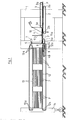
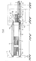
- a machine frame 1 can be seen, on each of which two lower feed belts 2 and two upper feed belts 3 are mounted by means of their deflection rollers 2a and 3a.
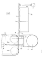
- These feed belts 2 and 3 which run parallel to one another in accordance with the plan view in FIG. 3, engage on the underside or on the top of flat-folded folding boxes F which come from a folding box gluing machine (not shown).
- the speed of the feed belts 2 and 3 is greater than the transport speed of the carton gluer.
- each folding box F is supplied with two pull belts 4, which likewise run on deflection rollers 4a and 4b at a speed corresponding to the feed belts 2 and 3.
- the front deflection roller 4a is arranged behind and above the lower feed belt 2 in the transport direction of the folding boxes F, so that it slightly raises the respectively arriving folding box F.
- the upper run of the straps 4 drops slightly towards the rear in that the diameter of the rear pulley 4b is smaller than that of the front pulley 4a.
- the suit straps 4 serve to form a stack in cooperation with stops to be described in more detail and, on the other hand, to constantly pull the folding boxes F of this stack against these stops by pulling on the bottom folding box F as a result of the continuously rotating pulling straps 4, in the direction of is exercised on the attacks.
- the stops for forming the stack consist of two stop angles 5 arranged laterally according to the width of the folding boxes F and two individual stops 6 arranged below the stop angles 5.
- the stop angles 5 have a rectangular cross section with a fixed leg 5a running parallel to the transport device of the folding boxes F. serves as a lateral guide for the respective front corner of the folding boxes F and can be adjusted to the respective width of the front edge of the folding box by laterally adjusting the stop angle 5.
- the leg 5b running parallel to the front edge of the folding boxes F. the stop bracket 5 serves to abut the folding box front edges and can be pivoted forward about the apex of the stop bracket 5, so that the folding boxes F merged into a stack can be released at a suitable moment for further transport.
- the pivoting of the front leg 5b of the stop brackets 5 is in each case carried out by a pressure medium cylinder 7, which acts on the movable leg 5b by means of a piston rod 7a.
- the folding box F delivered by the feed belts 2 and 3 meets with its front edge according to FIGS. 1 and 2 on the pulling belt 4 guided over the front deflection roller 4a and is raised slightly by it.
- This lifting is supported in the illustrated embodiment by two rollers 8, which can be seen in the top view in FIG. 3.
- These rollers 8 lie between the tightening straps 4 and have a circumference which corresponds to the shape of the tightening strap 4 guided over the front deflection roller 4a.
- Each arriving folding box F is pulled with its front edge by the straps 4 against the two individual stops 6, as can best be seen in FIGS. 1 and 2.
- These individual stops 6 correspond to the legs 5b of the stop angle 5, which begin only above the lowest folding box F of the stack being formed. This means that upon arrival each folding box F runs against the individual stops 6, but after being lifted by a new folding box F it is held in the position assumed by the stop angles 5.
- the individual stops 6 are Z-shaped in vertical section and by means of the piston rod 9a of a pressure medium cylinder ders 9 pivotable about a horizontal axis 6a in the counterclockwise direction. Swiveling the front legs 5b of the two stop angles 5 and the individual stops 6 thus clears the way for further transport of the stack formed in front of the stops 5 and 6.
- two hold-down devices 10 are arranged, which can be seen in the side view in FIGS. 1 and 2 and in the top view in FIG. 3.
- a microswitch or photocell is used to determine when the predetermined number of folding boxes F has been reached, so that the stack formation is complete and the stack can be transported further.
- stack feed elements are provided which are formed by two turntables 11 in the exemplary embodiment shown.
- These turntables 11 have the shape of a semicircle and are attached to an axis 11a which is mounted vertically outside the transport path for the folding boxes F.
- the turntables 11 are twisted in the manner of a half-worm gear, so that when they rotate, which leads them with their contact surface under the bottom folding box F of the stack, they also cause this stack to be lifted, due to their twisting in the manner of half Worm or thread.
- each turntable 11 has a drive rod 11b, which comes to rest when the turntable 11 is rotated at the rear edge of the stacked folding boxes F and moves the lifted stack further in the transport direction during the further rotational movement.
- the movable legs 5b were the stop angle 5 and the individual stops 6 by means of the pressure medium cylinder the 7 and 9 moved out of their locked position.
- the stack formed in cooperation with the stop angles 5 and individual stops 6 can in this way be fed specifically to a downstream transport device which, in the exemplary embodiment shown, consists of three transport belts 12 for supporting the stack and three press belts 13 which are above the transport belts 12 at a predetermined distance are arranged and press on the transferred stack from above to prevent this stack from disintegrating.
- Each transport belt 12 or press belt 13 is guided over a plurality of deflection rollers 12a or 13a.
- the front deflection rollers 13a of the press belt 13 are arranged according to FIGS. 1 and 2 such that there is a funnel-like inlet slope for the stack.
- the rear deflection rollers 12a and 13a of the transport belts 12 and press belts 13 are arranged on a movable bridge holder 14, with the aid of which the removal of the stack lying between the transport belts 12 and 13 can be adapted to the subsequent machine, which is preferably a manual one operable or fully automatic bundling machine.
- each individual stop 6 is formed by a freely rotatable roller 15, which is shown in FIGS 4 and 5 can be seen.
- stacking thus always includes a counting process with respect to the folding boxes F to be combined, whereby it is of course possible to change the number of folding boxes F combined into a stack.
Priority Applications (1)
| Application Number | Priority Date | Filing Date | Title |
|---|---|---|---|
| AT80107510T ATE5701T1 (de) | 1979-12-12 | 1980-12-02 | Vorrichtung zum stapeln von aus einer faltschachtelklebemaschine kommenden faltschachteln. |
Applications Claiming Priority (2)
| Application Number | Priority Date | Filing Date | Title |
|---|---|---|---|
| DE2949896 | 1979-12-12 | ||
| DE2949896A DE2949896C2 (de) | 1979-12-12 | 1979-12-12 | Vorrichtung zum Stapeln von aus einer Faltschachtelklebemaschine kommenden Faltschachteln |
Publications (2)
| Publication Number | Publication Date |
|---|---|
| EP0030672A1 true EP0030672A1 (fr) | 1981-06-24 |
| EP0030672B1 EP0030672B1 (fr) | 1983-12-28 |
Family
ID=6088213
Family Applications (1)
| Application Number | Title | Priority Date | Filing Date |
|---|---|---|---|
| EP80107510A Expired EP0030672B1 (fr) | 1979-12-12 | 1980-12-02 | Dispositif pour l'empilage de cartons pliants provenant d'une colleuse de cartons pliants |
Country Status (3)
| Country | Link |
|---|---|
| EP (1) | EP0030672B1 (fr) |
| AT (1) | ATE5701T1 (fr) |
| DE (2) | DE2949896C2 (fr) |
Cited By (3)
| Publication number | Priority date | Publication date | Assignee | Title |
|---|---|---|---|---|
| GB2182645A (en) * | 1985-11-11 | 1987-05-20 | Bobst Sa | Forming batches from a moving stream of flat articles |
| FR2651461A1 (fr) * | 1989-08-30 | 1991-03-08 | Ishikawa Seisakusho Kk | Dispositif pour empiler des boites en carton ondule dans une machine de fabrication de boites en carton ondule. |
| CN111115332A (zh) * | 2020-01-09 | 2020-05-08 | 泰州海达塑胶包装有限公司 | 塑料袋输送装置 |
Families Citing this family (2)
| Publication number | Priority date | Publication date | Assignee | Title |
|---|---|---|---|---|
| DE10347166A1 (de) * | 2003-10-06 | 2005-04-28 | Wilhelm Bahmueller Maschb Prae | Vorrichtung zum Stapeln von flachen Produkten |
| CN114920060B (zh) * | 2022-06-30 | 2023-04-07 | 安徽振新孛辰机械制造有限公司 | 一种纸板压平叠纸机及纸板生产线 |
Citations (8)
| Publication number | Priority date | Publication date | Assignee | Title |
|---|---|---|---|---|
| DE413880C (de) * | 1924-02-19 | 1925-05-22 | Joseph Renger | Stapelvorrichtung zum gleichmaessigen Aufschichten von gleichartigen, ebenen Sammelstuecken, insbesondere Faltschachteln, Karten o. dgl. |
| US2963177A (en) * | 1957-03-13 | 1960-12-06 | S & S Corrugated Paper Mach | Blank stacking, straightening and delivery device |
| DE1207200B (de) * | 1962-01-18 | 1965-12-16 | Sunds Verkstaeder Aktiebolag | Vorrichtung zum Stapeln von Karton-zuschnitten u. dgl. |
| DE1233247B (de) * | 1962-05-17 | 1967-01-26 | Hamilton Tool Co | Vorrichtung zum Stapeln von Papierboegen |
| US3420387A (en) * | 1967-01-05 | 1969-01-07 | Koppers Co Inc | Blank handling apparatus |
| DE1506929A1 (de) * | 1967-05-02 | 1969-08-07 | Inst Nahrungsmittel Genussmitt | Verfahren und Vorrichtung zum Stapeln von Stapeleinheiten,insbesondere Flaschenkaesten |
| US3744649A (en) * | 1972-05-05 | 1973-07-10 | Ward Machinery Co | Squaring and bundle counting machine |
| DD112957A1 (fr) * | 1974-08-30 | 1975-05-12 |
Family Cites Families (1)
| Publication number | Priority date | Publication date | Assignee | Title |
|---|---|---|---|---|
| US3601265A (en) * | 1968-11-27 | 1971-08-24 | S & S Corrugated Paper Mach | Blank stacking, straightening and delivery means |
-
1979
- 1979-12-12 DE DE2949896A patent/DE2949896C2/de not_active Expired
-
1980
- 1980-12-02 DE DE8080107510T patent/DE3066030D1/de not_active Expired
- 1980-12-02 EP EP80107510A patent/EP0030672B1/fr not_active Expired
- 1980-12-02 AT AT80107510T patent/ATE5701T1/de not_active IP Right Cessation
Patent Citations (8)
| Publication number | Priority date | Publication date | Assignee | Title |
|---|---|---|---|---|
| DE413880C (de) * | 1924-02-19 | 1925-05-22 | Joseph Renger | Stapelvorrichtung zum gleichmaessigen Aufschichten von gleichartigen, ebenen Sammelstuecken, insbesondere Faltschachteln, Karten o. dgl. |
| US2963177A (en) * | 1957-03-13 | 1960-12-06 | S & S Corrugated Paper Mach | Blank stacking, straightening and delivery device |
| DE1207200B (de) * | 1962-01-18 | 1965-12-16 | Sunds Verkstaeder Aktiebolag | Vorrichtung zum Stapeln von Karton-zuschnitten u. dgl. |
| DE1233247B (de) * | 1962-05-17 | 1967-01-26 | Hamilton Tool Co | Vorrichtung zum Stapeln von Papierboegen |
| US3420387A (en) * | 1967-01-05 | 1969-01-07 | Koppers Co Inc | Blank handling apparatus |
| DE1506929A1 (de) * | 1967-05-02 | 1969-08-07 | Inst Nahrungsmittel Genussmitt | Verfahren und Vorrichtung zum Stapeln von Stapeleinheiten,insbesondere Flaschenkaesten |
| US3744649A (en) * | 1972-05-05 | 1973-07-10 | Ward Machinery Co | Squaring and bundle counting machine |
| DD112957A1 (fr) * | 1974-08-30 | 1975-05-12 |
Cited By (5)
| Publication number | Priority date | Publication date | Assignee | Title |
|---|---|---|---|---|
| GB2182645A (en) * | 1985-11-11 | 1987-05-20 | Bobst Sa | Forming batches from a moving stream of flat articles |
| GB2182645B (en) * | 1985-11-11 | 1989-11-08 | Bobst Sa | Forming batches of flat articles |
| FR2651461A1 (fr) * | 1989-08-30 | 1991-03-08 | Ishikawa Seisakusho Kk | Dispositif pour empiler des boites en carton ondule dans une machine de fabrication de boites en carton ondule. |
| CN111115332A (zh) * | 2020-01-09 | 2020-05-08 | 泰州海达塑胶包装有限公司 | 塑料袋输送装置 |
| CN111115332B (zh) * | 2020-01-09 | 2021-04-23 | 泰州海达塑胶包装有限公司 | 塑料袋输送装置 |
Also Published As
| Publication number | Publication date |
|---|---|
| ATE5701T1 (de) | 1984-01-15 |
| DE2949896C2 (de) | 1982-11-25 |
| DE2949896A1 (de) | 1981-06-19 |
| DE3066030D1 (en) | 1984-02-02 |
| EP0030672B1 (fr) | 1983-12-28 |
Similar Documents
| Publication | Publication Date | Title |
|---|---|---|
| DE3125370C2 (fr) | ||
| DD144393A5 (de) | Stapelvorrichtung fuer faltschachteln | |
| CH457268A (de) | Vorrichtung zum Ablegen flächenhafter Gegenstände zu einem Stapel | |
| DE3421915C2 (fr) | ||
| DE3129709A1 (de) | Maschine zum schliessen der oberen deckelklappen eines quaderfoermigen kartons mit faltklappen | |
| DE1274493B (de) | Vorrichtung zum Umwickeln eines Stapels nachgiebigen Flachmaterials | |
| DE3103149A1 (de) | Automatische maschine zum kontinuierlichen abpacken von produkten | |
| EP0030672B1 (fr) | Dispositif pour l'empilage de cartons pliants provenant d'une colleuse de cartons pliants | |
| DE1131979B (de) | Stapelvorrichtung fuer bogenfoermiges Material | |
| DE2646944A1 (de) | Muenzenstapel-abstuetzvorrichtung in einer muenzen-verpackungsmaschine | |
| CH618939A5 (fr) | ||
| DE2644892C3 (de) | Maschine zum Verpacken von Kaugummistreifen | |
| DE2846020C2 (fr) | ||
| CH644504A5 (de) | Vorrichtung zur anbringung von schiebern an reissverschlussstreifen. | |
| EP0006249B1 (fr) | Dipositif pour revêtir une pile d'articles d'une gaine tubulaire en matière synthétique thermocontractile | |
| DE19630762C2 (de) | Verfahren und Vorrichtung zur Bildung von Schuppenformationen bedruckter Bogen | |
| CH457515A (de) | Nonstop-Bogenstapler | |
| DE1574162B2 (de) | Vorrichtung zum entwickeln von muenzen | |
| DE2913706C2 (de) | Vorrichtung zum Stapeln und Einwickeln von Münzen o.dgl. | |
| DE2609106A1 (de) | Vorrichtung zur uebergabe von flachen gegenstaenden in behaelter | |
| DE2505164C2 (de) | Rundstapelbogenanleger | |
| EP1352853A2 (fr) | Dispositif de transport d'articles se chevauchant, en particulier pour emballer des cartons pliés plats | |
| DE4007481C2 (fr) | ||
| DE3238184C1 (de) | Umreifungsmaschine für das Umreifen von Packgütern | |
| DE2320096A1 (de) | Klemmvorrichtung fuer stoff-auslegemaschinen |
Legal Events
| Date | Code | Title | Description |
|---|---|---|---|
| PUAI | Public reference made under article 153(3) epc to a published international application that has entered the european phase |
Free format text: ORIGINAL CODE: 0009012 |
|
| AK | Designated contracting states |
Designated state(s): AT BE CH DE FR GB IT LU NL SE |
|
| 17P | Request for examination filed |
Effective date: 19811107 |
|
| ITF | It: translation for a ep patent filed |
Owner name: ING. ZINI MARANESI & C. S.R.L. |
|
| GRAA | (expected) grant |
Free format text: ORIGINAL CODE: 0009210 |
|
| AK | Designated contracting states |
Designated state(s): AT BE CH DE FR GB IT LI LU NL SE |
|
| REF | Corresponds to: |
Ref document number: 5701 Country of ref document: AT Date of ref document: 19840115 Kind code of ref document: T |
|
| REF | Corresponds to: |
Ref document number: 3066030 Country of ref document: DE Date of ref document: 19840202 |
|
| ET | Fr: translation filed | ||
| PLBE | No opposition filed within time limit |
Free format text: ORIGINAL CODE: 0009261 |
|
| STAA | Information on the status of an ep patent application or granted ep patent |
Free format text: STATUS: NO OPPOSITION FILED WITHIN TIME LIMIT |
|
| 26N | No opposition filed | ||
| PG25 | Lapsed in a contracting state [announced via postgrant information from national office to epo] |
Ref country code: LU Free format text: LAPSE BECAUSE OF NON-PAYMENT OF DUE FEES Effective date: 19841231 |
|
| PGFP | Annual fee paid to national office [announced via postgrant information from national office to epo] |
Ref country code: SE Payment date: 19841231 Year of fee payment: 5 Ref country code: BE Payment date: 19841231 Year of fee payment: 5 |
|
| PGFP | Annual fee paid to national office [announced via postgrant information from national office to epo] |
Ref country code: DE Payment date: 19850212 Year of fee payment: 5 |
|
| PGFP | Annual fee paid to national office [announced via postgrant information from national office to epo] |
Ref country code: AT Payment date: 19861222 Year of fee payment: 7 |
|
| PGFP | Annual fee paid to national office [announced via postgrant information from national office to epo] |
Ref country code: NL Payment date: 19861231 Year of fee payment: 7 |
|
| PG25 | Lapsed in a contracting state [announced via postgrant information from national office to epo] |
Ref country code: AT Effective date: 19871202 |
|
| PG25 | Lapsed in a contracting state [announced via postgrant information from national office to epo] |
Ref country code: SE Effective date: 19871203 |
|
| PG25 | Lapsed in a contracting state [announced via postgrant information from national office to epo] |
Ref country code: LI Effective date: 19871231 Ref country code: CH Effective date: 19871231 Ref country code: BE Effective date: 19871231 |
|
| BERE | Be: lapsed |
Owner name: GUSCHKY & TONNESMANN G.M.B.H. & CO. K.G. Effective date: 19871231 |
|
| PG25 | Lapsed in a contracting state [announced via postgrant information from national office to epo] |
Ref country code: NL Effective date: 19880701 |
|
| GBPC | Gb: european patent ceased through non-payment of renewal fee | ||
| NLV4 | Nl: lapsed or anulled due to non-payment of the annual fee | ||
| PG25 | Lapsed in a contracting state [announced via postgrant information from national office to epo] |
Ref country code: FR Free format text: LAPSE BECAUSE OF NON-PAYMENT OF DUE FEES Effective date: 19880831 |
|
| REG | Reference to a national code |
Ref country code: CH Ref legal event code: PL |
|
| PG25 | Lapsed in a contracting state [announced via postgrant information from national office to epo] |
Ref country code: DE Effective date: 19880901 |
|
| REG | Reference to a national code |
Ref country code: FR Ref legal event code: ST |
|
| PG25 | Lapsed in a contracting state [announced via postgrant information from national office to epo] |
Ref country code: GB Effective date: 19881118 |
|
| EUG | Se: european patent has lapsed |
Ref document number: 80107510.2 Effective date: 19880912 |