EP0030672A1 - Device for stacking folding boxes coming out of a folding box glueing machine - Google Patents
Device for stacking folding boxes coming out of a folding box glueing machine Download PDFInfo
- Publication number
- EP0030672A1 EP0030672A1 EP80107510A EP80107510A EP0030672A1 EP 0030672 A1 EP0030672 A1 EP 0030672A1 EP 80107510 A EP80107510 A EP 80107510A EP 80107510 A EP80107510 A EP 80107510A EP 0030672 A1 EP0030672 A1 EP 0030672A1
- Authority
- EP
- European Patent Office
- Prior art keywords
- stack
- stop
- folding
- transport
- belts
- Prior art date
- Legal status (The legal status is an assumption and is not a legal conclusion. Google has not performed a legal analysis and makes no representation as to the accuracy of the status listed.)
- Granted
Links
Images


Classifications
-
- B—PERFORMING OPERATIONS; TRANSPORTING
- B65—CONVEYING; PACKING; STORING; HANDLING THIN OR FILAMENTARY MATERIAL
- B65H—HANDLING THIN OR FILAMENTARY MATERIAL, e.g. SHEETS, WEBS, CABLES
- B65H31/00—Pile receivers
- B65H31/30—Arrangements for removing completed piles
- B65H31/3081—Arrangements for removing completed piles by acting on edge of the pile for moving it along a surface, e.g. by pushing
-
- B—PERFORMING OPERATIONS; TRANSPORTING
- B65—CONVEYING; PACKING; STORING; HANDLING THIN OR FILAMENTARY MATERIAL
- B65H—HANDLING THIN OR FILAMENTARY MATERIAL, e.g. SHEETS, WEBS, CABLES
- B65H29/00—Delivering or advancing articles from machines; Advancing articles to or into piles
- B65H29/16—Delivering or advancing articles from machines; Advancing articles to or into piles by contact of one face only with moving tapes, bands, or chains
- B65H29/18—Delivering or advancing articles from machines; Advancing articles to or into piles by contact of one face only with moving tapes, bands, or chains and introducing into a pile
-
- B—PERFORMING OPERATIONS; TRANSPORTING
- B65—CONVEYING; PACKING; STORING; HANDLING THIN OR FILAMENTARY MATERIAL
- B65H—HANDLING THIN OR FILAMENTARY MATERIAL, e.g. SHEETS, WEBS, CABLES
- B65H31/00—Pile receivers
- B65H31/30—Arrangements for removing completed piles
- B65H31/3027—Arrangements for removing completed piles by the nip between moving belts or rollers
-
- B—PERFORMING OPERATIONS; TRANSPORTING
- B31—MAKING ARTICLES OF PAPER, CARDBOARD OR MATERIAL WORKED IN A MANNER ANALOGOUS TO PAPER; WORKING PAPER, CARDBOARD OR MATERIAL WORKED IN A MANNER ANALOGOUS TO PAPER
- B31B—MAKING CONTAINERS OF PAPER, CARDBOARD OR MATERIAL WORKED IN A MANNER ANALOGOUS TO PAPER
- B31B50/00—Making rigid or semi-rigid containers, e.g. boxes or cartons
- B31B50/74—Auxiliary operations
- B31B50/92—Delivering
- B31B50/98—Delivering in stacks or bundles
-
- B—PERFORMING OPERATIONS; TRANSPORTING
- B65—CONVEYING; PACKING; STORING; HANDLING THIN OR FILAMENTARY MATERIAL
- B65H—HANDLING THIN OR FILAMENTARY MATERIAL, e.g. SHEETS, WEBS, CABLES
- B65H2301/00—Handling processes for sheets or webs
- B65H2301/40—Type of handling process
- B65H2301/42—Piling, depiling, handling piles
- B65H2301/421—Forming a pile
- B65H2301/4212—Forming a pile of articles substantially horizontal
- B65H2301/42122—Forming a pile of articles substantially horizontal by introducing articles from under the pile
-
- B—PERFORMING OPERATIONS; TRANSPORTING
- B65—CONVEYING; PACKING; STORING; HANDLING THIN OR FILAMENTARY MATERIAL
- B65H—HANDLING THIN OR FILAMENTARY MATERIAL, e.g. SHEETS, WEBS, CABLES
- B65H2701/00—Handled material; Storage means
- B65H2701/10—Handled articles or webs
- B65H2701/17—Nature of material
- B65H2701/176—Cardboard
- B65H2701/1766—Cut-out, multi-layer, e.g. folded blanks or boxes
Abstract
Description
Die Erfindung betrifft eine Vorrichtung zum Stapeln von aus einer Faltschachtelklebemaschine kommenden, flach zusammengelegten Faltschachteln mit die Faltschachteln an der Ober- und Unterseite angreifenden Einzugriemen, deren Geschwindigkeit größer als die Transportgeschwindigkeit der Klebemaschine ist.The invention relates to a device for stacking flat folded folding boxes coming from a folding box gluing machine, with feed belts attacking the folding boxes on the top and bottom, the speed of which is greater than the transport speed of the gluing machine.
Vorrichtungen der voranstehend beschriebenen Art sind bekannt. Mit ihnen können jedoch nur Schachteln mit gerader Vorderkante und glattflächiger Ober- und Unterseite gestapelt werden. Anderweitig ausgebildete Faltschachteln, beispielsweise mit seitlich angeformtem Deckel und damit unterbrochener Vorderkante oder mit auf der Oberfläche der Faltschachtel aufliegenden Lappen erfordern einen Stapelvorgang von Hand.Devices of the type described above are known. However, they can only be used to stack boxes with a straight front edge and smooth top and bottom surfaces. Folding boxes of a different design, for example with a laterally formed lid and thus an interrupted leading edge or with rags resting on the surface of the folding box, require a manual stacking process.
Der Erfindung liegt die Aufgabe zugrunde, zur Vermeidung der Nachteile des bekannten Standes der Technik eine Vorrichtung der eingangs beschriebenen Art derart weiterzubilden, daß auch unterschiedlichste Faltschachteln mit von der geraden Linie abweichender Vorder- und/oder Hinterkante, mit Deckel und mit auf der Oberfläche aufliegenden Lappen zuverlässig gestapelt werden können.The invention has for its object to avoid the disadvantages of the known prior art, a device of the type described in such a way that a wide variety of folding boxes with the front and / or back deviating from the straight line edge, with a lid and with rags resting on the surface can be reliably stacked.
Die Lösung dieser Aufgabenstellung durch die Erfindung ist dadurch gekennzeichnet, daß in Transportrichtung hinter und oberhalb des unteren Einzugriemens die vordere Umlenkrolle eines Anzugriemens angeordnet ist, durch welchen die jeweils ankommende Faltschachtel unter einen sich bildenden Stapel gezogen wird, dessen Faltschachteln mit ihren vorderen Ecken an seitlich angeordneten Anschlagwinkeln anliegen, daß die Anschlagwinkel nach Bildung eines fertigen Stapels aus der Halteposition herausbewegbar sind und Stapelvorschubelemente den Stapel einem Transport- und Preßriemenpaar zuführen und daß unterhalb jedes Anschlagwinkels ein Einzelanschlag für die jeweils ankommende Faltschachtel angeordnet ist, der unabhängig vom Anschlagwinkel bei Beginn der Stapelübergabe aus seiner Sperrposition herausbewegbar und sofort nach Übergabe der Stapelvorderkante auf die Transportund Preßriemen wieder in seine Sperrposition überführbar ist.The solution to this problem by the invention is characterized in that the front deflection roller of a suit belt is arranged behind and above the lower feed belt in the transport direction, through which the respectively arriving folding box is pulled under a stack that is formed, the folding boxes of which have their front corners on the side Arranged stop angles are that the stop angles can be moved out of the holding position after formation of a finished stack and stack feed elements feed the stack to a pair of transport and press belts and that a single stop for the incoming folding box is arranged below each stop angle, which is independent of the stop angle at the start of the stack transfer can be moved out of its locked position and can be transferred back to its locked position immediately after the stack leading edge has been transferred to the transport and press belt.
Mit diesem Vorschlag der Erfindung wird eine Stapelvorrichtung geschaffen, mit der beliebig ausgebildete Faltschachteln, die aus einer Faltschachtelklebemaschine kommen und flach zusammengelegt sind, zu Stapeln vorbestimmter Zahl gestapelt werden können. Jede aus der Faltschachtelklebemaschine kommende Faltschachtel wird durch die an ihrer Ober- und Unterseite angreifenden Anzugriemen, deren Geschwindigkeit größer als die Transportgeschwindigkeit der Klebemaschine ist, abgezogen und unter einen sich bildenden Stapel geführt. Die in Transportrichtung der ankommenden Faltschachtel hinter und oberhalb des unteren Einzugriemens angeordnete Umlenkrolle des Anzugriemens sorgt hierbei dafür, daß der Stapel mit jeder neu hinzukommenden Faltschachtel angehoben wird, weil diese beim Auftreffen auf den Umfang der vorderen Umlenkrolle angehoben und unter den Stapel gezogen wird. Da der Anzugriemen kontinuierlich umläuft, bewirkt er gleichzeitig ein ständiges leichtes Vorziehen sämtlicher Faltschachteln des Stapels, so daß diese mit ihrer Vorderkante im Eckenbereich fest an den seitlich angeordneten Anschlagwinkeln anliegen.With this proposal of the invention, a stacking device is created with which arbitrarily designed folding boxes, which come from a folding box gluing machine and are folded flat, can be stacked into stacks of a predetermined number. Each folding box coming out of the folding box gluing machine is pulled off by the pulling straps acting on its upper and lower sides, the speed of which is greater than the transport speed of the gluing machine, and guided under a stack that is being formed. The deflection arranged behind and above the lower feed belt in the transport direction of the incoming folding box Roll of the suit strap ensures that the stack is lifted with each new folding box, because it hits the circumference of the front deflection roller when it hits it and is pulled under the stack. Since the suit belt rotates continuously, at the same time it causes all the folding boxes of the stack to be pulled forward slightly so that their front edge lies firmly against the side-mounted stop angles in the corner area.
Diese Anschlagwinkel sind aus ihrer Halteposition herausbewegbar, so daß sie nach Bildung eines fertigen Stapels den Transportweg für diesen Stapel freigeben. Der fertige Stapel wird durch Stapelvorschubelemente geringfügig angehoben und einem Transport- und Preßriemenpaar zugeführt, das sich in Transportrichtung hinter der Stapelstelle befindet. Zwischen diesen Transport- und Preßriemen werden die einzelnen Stapel in einer Art Zwischenspeicher aufbewahrt und kontinuierlich aus der Vorrichtung herausgefördert.These stop angles can be moved out of their holding position, so that they release the transport path for this stack after the formation of a finished stack. The finished stack is slightly raised by stack feed elements and fed to a pair of transport and press belts, which is located behind the stacking point in the transport direction. Between these transport belts and press belts, the individual stacks are stored in a kind of intermediate storage and continuously conveyed out of the device.
Damit jede ankommende Faltschachtel exakt in Übereinstimmung mit den Faltschachteln des darüber befindlichen Stapels festgehalten wird, ist unterhalb jedes Anschlagwinkels ein Einzelanschlag angeordnet. Dieser ist unabhängig vom Anschlagwinkel bei Beginn der Stapelübergabe aus seiner Sperrposition herausbewegbar, so daß er einer Übergabe des fertigen Stapels an das Transport- und Preßriemenpaar nicht hindernd im Wege steht, insbesondere nicht die jeweils unterste Faltschachtel festhält. Sobald jedoch die unterste Faltschachtel mit ihrer Vorderkante den Einzelanschlag passiert hat, wird dieser wieder in seine Sperrposition überführt, so daß eine von den Einzugriemen herangebrachte Faltschachtel zuverlässig in der Stapelposition festgehalten wird, auch wenn sich der Stapel noch nicht vollständig zwischen den Transport- und Preßriemen befindet.So that each incoming folding box is held exactly in accordance with the folding boxes of the stack above, a single stop is arranged below each stop angle. This can be moved out of its locked position regardless of the stop angle at the start of the stack transfer, so that it does not hinder the transfer of the finished stack to the pair of transport and press belts, in particular does not hold the bottom folding box. However, as soon as the bottom folding box has passed the single stop with its front edge, this is brought back into its blocking position, so that a folding box brought up by the pull-in straps is closed is casually held in the stacking position, even if the stack is not yet completely between the transport and press belts.
Da die voranstehend beschriebenen Teile der erfindungsgemäßen Vorrichtung einzeln einstellbar sind, kann die Vorrichtung ohne Schwierigkeiten auf jeden beliebigen Grundriß oder Querschnitt einer Faltschachtel ausgerichtet werden. Die erfindungsgemäße Vorrichtung kann somit auch komplizierte und mit den bekannten Vorrichtungen nicht stapelbare Faltschachteln zuverlässig stapeln.Since the parts of the device according to the invention described above are individually adjustable, the device can be aligned without difficulty to any plan or cross-section of a folding box. The device according to the invention can thus also reliably stack complicated folding boxes that are not stackable with the known devices.
Gemäß einem weiteren Merkmal der Erfindung werden die Stapelvorschubelemente durch zwei Drehteller gebildet, die jeweils eine halbkreisförmige und in der Art eines halben Schneckengangs verwundene Auflagefläche mit einem senkrecht stehenden Mitnahmestab aufweisen und um eine senkrechte, seitlich außerhalb der Transportbahn für die Faltschachteln liegende Achse drehbar gelagert sind. Mit diesen erfindungsgemäß ausgebildeten Stapelvorschubelementen wird der fertige Stapel geringfügig angehoben, indem der halbkreisförmige und in der Art eines halben Schneckenganges verwundene Drehteller um 180° gedreht wird. Er gelangt mit seiner Auflagefläche hierbei aus einer außerhalb der Transportbahn liegenden Ruhestellung unterhalb die unterste Faltschachtel des Stapels, hebt diesen so weit an, daß er höher als der untere Transportund Preßriemen liegt und bewirkt anschließend mittels seines Mitnahmestabes bei weitergehender Drehung, daß dieser an der Hinterkante der Faltschachteln anliegende Stab den Stapel zwischen die Transport- und Preßriemen transportiert. Der obere Transport- und Preßriemen hat vorzugsweise an seiner Vorderseite einen trichterförmig ausgebildeten Einlauf. Nach Übergabe des Stapels an die Transport- und Preßriemen kehrt der Drehteller in seine Ausgangsposition zurück, in der sowohl die halbkreisförmige Auflagefläche als auch der Mitnahmestab außerhalb der Transportbahn für die Faltschachteln liegen.According to a further feature of the invention, the stack feed elements are formed by two turntables, each of which has a semicircular support surface which is twisted in the manner of a half-worm gear with a vertically standing driving rod and is rotatably mounted about a vertical axis lying laterally outside the transport path for the folding boxes . With these stack feed elements designed according to the invention, the finished stack is raised slightly by rotating the semicircular turntable twisted in the manner of a half-worm gear by 180 °. It comes with its contact surface from a rest position lying outside the transport path below the bottom folding box of the stack, lifts it so far that it is higher than the lower transport and press belt and then, by means of its driving rod, causes it to rotate at the rear edge when the rotation continues the stick of the folding carton transports the stack between the transport and press belts. The upper transport and press belt preferably has a funnel-shaped inlet on its front. After handing over the stack to The turntable returns the transport and press belt to its starting position, in which both the semicircular contact surface and the driving bar lie outside the transport path for the folding boxes.
Bei einer bevorzugten Ausführungsform der Erfindung ist der als Anschlag für die Vorderkante der gestapelten Faltschachteln dienende Schenkel der Anschlagwinkel um den Scheitel des jeweiligen Anschlagwinkels verschwenkbar gelagert. Hierdurch ergibt sich eine besonders einfache Ausführungsform für den Anschlagwinkel, dessen seitlich und parallel zur Transporteinrichtung liegender Schenkel starr ausgebildet ist. Das Verschwenken des vorderen, an der Vorderkante der gestapelten Faltschachteln anliegenden Schenkels kann beispielsweise mittels eines Preßluftzylinders erfolgen.In a preferred embodiment of the invention, the leg serving as a stop for the front edge of the stacked folding boxes of the stop angle is pivotally mounted about the apex of the respective stop angle. This results in a particularly simple embodiment for the stop angle, the side of which and the leg lying parallel to the transport device is rigid. The pivoting of the front leg, which lies against the front edge of the stacked folding boxes, can take place, for example, by means of a compressed air cylinder.
Derartige Preßluftzylinder können auch zur Betätigung der Einzelanschläge angeordnet sein, die gemäß einem weiteren Merkmal der Erfindung als im senkrechten Schnitt Z-förmige Klappe ausgebildet sein können, welche um eine waagerechte Achse verschwenkbar gelagert ist. Um die Reibung zwischen der Oberkante dieser noch während des Passierens des Stapels in die Sperrposition zurückgeschwenkten Klappe und der jeweils untersten Faltschachtel herabzusetzen, wird mit der Erfindung schließlich vorgeschlagen, diese Oberkante der Klappe durch eine frei drehbare Rolle zu bilden.Compressed air cylinders of this type can also be arranged to actuate the individual stops, which according to a further feature of the invention can be designed as a Z-shaped flap in vertical section, which is pivotally mounted about a horizontal axis. In order to reduce the friction between the upper edge of this flap, which is pivoted back into the blocking position while it is still passing the stack, and the bottom folding box, the invention finally proposes to form this upper edge of the flap by means of a freely rotatable roller.
Insgesamt ergibt sich mit dem erfindungsgemäßen Vorschlag eine Vorrichtung zum Stapeln von aus einer Faltschachtelklebemaschine kommenden Faltschachteln, die universell einsetzbar ist, einen einfachen konstruktiven Aufbau besitzt und auch bei hohen Geschwindigkeiten mit großer Funktionssicherheit arbeitet, weil außer kontinuierlich umlaufenden Riemen nur wenige gesteuerte Bewegungen stattfinden, die zudem durch die erfindungsgemäße Aufteilung mit der notwendigen Präzision innerhalb eines ausreichend bemessenen Zeitraumes ablaufen.Overall, the proposal according to the invention results in a device for stacking folding boxes coming from a folding-box gluing machine, which can be used universally, has a simple construction and is also large at high speeds Functional reliability works because, apart from the continuously rotating belts, only a few controlled movements take place, which moreover take place with the necessary precision within a sufficiently dimensioned period due to the division according to the invention.
Auf der Zeichnung ist ein Ausführungsbeispiel der erfindungsgemäßen Vorrichtung dargestellt, und zwar zeigen:
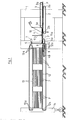
- Fig. 1 eine schematische Seitenansicht der gesamten Vorrichtung bei Beginn der Stapelbildung,
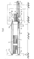
- Fig. 2 eine schematische Seitenansicht gemäß Fig. 1 mit nahezu fertigem Stapel,
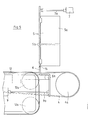
- Fig. 3 eine schematische Draufsicht auf die Vorrichtung nach den Fig. 1 und 2,
- Fig. 4 einen Schnitt gemäß der Schnittlinie IV-IV in Fig. 3 in vergrößertem Maßstab und
- Fig. 5 eine Seitenansicht zu Fig. 4.
- 1 is a schematic side view of the entire device at the start of stack formation,
- FIG. 2 shows a schematic side view according to FIG. 1 with an almost finished stack, FIG.
- 3 shows a schematic top view of the device according to FIGS. 1 and 2,
- Fig. 4 is a section along the section line IV-IV in Fig. 3 on an enlarged scale and
- 5 shows a side view of FIG. 4.
In der Seitenansicht der Fig. 1 bzw. 2 ist ein Maschinengestell 1 zu erkennen, an dem jeweils zwei untere Einzugriemen 2 und zwei obere Einzugriemen 3 mittels ihrer Umlenkrollen 2a bzw. 3a gelagert sind. Diese gemäß der Draufsicht in Fig. 3 parallel zueinander verlaufenden Einzugriemen 2 und 3 greifen an der Unterseite bzw. an der Oberseite von flach zusammengefalteten Faltschachteln F an, die aus einer nicht dargestellten Faltschachtelklebemaschine kommen. Um einen einwandfreien Abzug dieser Faltschachteln F zu gewährleisten, ist die Geschwindigkeit der Einzugriemen 2 und 3 größer als die Transportgeschwindigkeit der Faltschachtelklebemaschine.1 and 2, a
Von den insgesamt vier Einzugriemen 2 und 3 wird jede Faltschachtel F zwei Anzugriemen 4 zugeführt, die ebenfalls auf Umlenkrollen 4a und 4b mit einer den Einzugriemen 2 und 3 entsprechenden Geschwindigkeit umlaufen. Die vordere Umlenkrolle 4a ist in Transportrichtung der Faltschachteln F hinter und oberhalb des unteren Einzugriemens 2 angeordnet, so daß sie die jeweils ankommende Faltschachtel F geringfügig anhebt. Beim dargestellten Ausführungsbeispiel fällt das Obertrum der Anzugriemen 4 nach hinten dadurch geringfügig ab, daß der Durchmesser der hinteren Umlenkrolle 4b kleiner als der der vorderen Umlenkrolle 4a ist. Die Anzugriemen 4 dienen dazu, im Zusammenwirken mit noch näher zu beschreibenden Anschlägen einen Stapel zu bilden und andererseits die Faltschachteln F dieses Stapels ständig gegen diese Anschläge zu ziehen, indem auf die jeweils unterste Faltschachtel F infolge der kontinuierlich umlaufenden Anzugriemen 4 ein ständiger Zug in Richtung auf die Anschläge ausgeübt wird.Of the four
Die Anschläge zur Bildung des Stapels bestehen aus zwei seitlich entsprechend der Breite der Faltschachteln F angeordneten Anschlagwinkeln 5 und zwei unterhalb der Anschlagwinkel 5 angeordneten Einzelanschlägen 6. Die Anschlagwinkel 5 besitzen einen rechtwinkligen Querschnitt mit einem parallel zur Transporteinrichtung der Faltschachteln F verlaufenden feststehenden Schenkel 5a, der als seitliche Führung für die jeweilige vordere Ecke der Faltschachteln F dient und durch seitliches Verstellen der Anschlagwinkel 5 auf die jeweilige Breite der Faltschachtel-Vorderkante einstellbar ist. Der parallel zur Vorderkante der Faltschachteln F verlaufende Schenkel 5b der Anschlagwinkel 5 dient zur Anlage der Faltschachtel-Vorderkanten und ist um den Scheitel des Anschlagwinkels 5 nach vorn verschwenkbar, so daß die zu einem Stapel zusammengeführten Faltschachteln F im geeigneten Augenblick zum Weitertransport freigegeben werden können. Beim dargestellten Ausführungsbeispiel erfolgt die Verschwenkung des vorderen Schenkels 5b der Anschlagwinkel 5 jeweils durch einen Druckmittelzylinder 7, der mittels einer Kolbenstange 7a am beweglichen Schenkel 5b angreift.The stops for forming the stack consist of two
Die jeweils von den Einzugriemen 2 und 3 angelieferte Faltschachtel F trifft mit ihrer Vorderkante gemäß den Fig. 1 und 2 auf den über die vordere Umlenkrolle 4a geführten Anzugriemen 4 und wird von diesem geringfügig angehoben. Dieses Anheben wird beim dargestellten Ausführungsbeispiel durch zwei Rollen 8 unterstützt, die in der Draufsicht in Fig. 3 zu erkennen sind. Diese Rollen 8 liegen zwischen den Anzugriemen 4 und haben einen Umfang, der der Form des über die vordere Umlenkrolle 4a geführten Anzugriemens 4 entspricht. Jede ankommende Faltschachtel F wird mit ihrer Vorderkante von den Anzugriemen 4 gegen die beiden Einzelanschläge 6 gezogen, wie dies am besten in den Fig. 1 und 2 zu erkennen ist. Diese Einzelanschläge 6 korrespondieren mit den Schenkeln 5b der Anschlagwinkel 5, die erst oberhalb der jeweils untersten Faltschachtel F des sich bildenden Stapels beginnen. Dies bedeutet, daß beim Ankommen jede Faltschachtel F gegen die Einzelanschläge 6 läuft, nach einem Anheben durch eine neue Faltschachtel F jedoch in der eingenommenen Stellung durch die Anschlagwinkel 5 gehalten wird.The folding box F delivered by the
Beim dargestellten Ausführungsbeispiel sind die Einzelanschläge 6 im senkrechten Schnitt Z-förmig ausgebildet und mittels der Kolbenstange 9a eines Druckmittelzylinders 9 um eine waagerecht verlaufende Achse 6a im Gegenuhrzeigersinn verschwenkbar. Ein Verschwenken der vorderen Schenkel 5b der beiden Anschlagwinkel 5 und der Einzelanschläge 6 gibt somit den Weg zum Weitertransport des vor den Anschlägen 5 und 6 gebildeten Stapels frei. Um den Stapel zusammenzuhalten, sind zwei Niederhalter 10 angeordnet, die in der Seitenansicht in den Fig. 1 und 2 und in der Draufsicht in Fig. 3 zu erkennen sind. Mittels Mikroschalter oder Fotozelle wird festgestellt, wann die vorgegebene Zahl von Faltschachteln F erreicht ist, so daß die Stapelbildung abgeschlossen ist und der Stapel weitertransportiert werden kann.In the illustrated embodiment, the
Um diesen Weitertransport eines fertigen, an den Anschlägen 5 und 6 anliegenden Stapels zu bewerkstelligen, sind Stapelvorschubelemente vorgesehen, die beim dargestellten Ausführungsbeispiel durch zwei Drehteller 11 gebildet sind. Diese Drehteller 11 besitzen die Form eines Halbkreises und sind an einer Achse 11a befestigt, die außerhalb der Transportbahn für die Faltschachteln F senkrecht gelagert ist. Die Drehteller 11 sind in der Art eines halben Schneckenganges verwunden, so daß sie bei einer Drehbewegung, die sie mit ihrer Auflagefläche unter die unterste Faltschachtel F des Stapels führt, zugleich ein Anheben dieses Stapels bewirken, und zwar infolge ihrer Verwindung in der Art eines halben Schnecken- oder Gewindeganges. An der höherliegenden Ecke besitzt jeder Drehteller 11 einen Mitnahmestab 11b, der bei einem Verdrehen des Drehtellers 11 an der Hinterkante der gestapelten Faltschachteln F zur Anlage kommt und bei der weiteren Drehbewegung den angehobenen Stapel in Transportrichtung weiterbewegt. Um diese Weiterbewegung zu ermöglichen, wurden die beweglichen Schenkel 5b der Anschlagwinkel 5 und die Einzelanschläge 6 mittels der Druckmittelzylinder 7 und 9 aus ihrer Sperrstellung herausbewegt. Der im Zusammenwirken mit den Anschlagwinkeln 5 und Einzelanschlägen 6 gebildete Stapel kann auf diese Weise gezielt einer nachgeschalteten Transportvorrichtung zugeführt werden, die beim dargestellten Ausführungsbeispiel aus drei Transportriemen 12 zur Auflage des Stapels und drei Preßriemen 13 besteht, die oberhalb der Transportriemen 12 in einem vorgegebenen Abstand angeordnet sind und von oben auf den übergebenen Stapel drücken, um ein Zerfallen dieses Stapels zu verhindern. Jeder Transportriemen 12 bzw. Preßriemen 13 ist über eine Mehrzahl von Umlenkrollen 12a bzw. 13a geführt. Die vorderen Umlenkrollen 13a der Preßriemen 13 sind gemäß den Fig. 1 und 2 derart angeordnet, daß sich eine trichterähnliche Einlaufschräge für den Stapel ergibt. Die hinteren Umlenkrollen 12a und 13a der Transportriemen 12 und Preßriemen 13 sind an einer verfahrbaren Brückenhalterung 14 angeordnet, mit deren Hilfe der Abtransport der zwischen den Transport- und Preßriemen 12 und 13 liegenden Stapel an die nachfolgende Maschine angepaßt werden kann, die vorzugsweise eine von Hand bedienbare oder vollautomatische Bündelmaschine ist.In order to accomplish this further transport of a finished stack lying against the
Während der als Anschlag für die Vorderkante der gestapelten Faltschachteln F dienende Schenkel 5b der Anschlagwinkel 5 so lange verschwenkt wird, bis der gesamte Stapel den Anschlagwinkel 5 passiert hat, werden die Einzelanschläge 6 sofort nach Übergabe der Stapelvorderkante zwischen die Transport- und Preßriemen 12 und 13 in ihre Sperrposition zurückgeschwenkt, damit bereits die nächste von den Einzugriemen 2 und 3 angelieferte Faltschachtel F in der Stapelposition festgehalten wird. Auf diese Weise steht genügend Zeit für die Übergabe des fertigen Stapels aus der Stapelposition zwischen die Transport- und Preßriemen 12 und 13 zur Verfügung, weil bereits eine während dieser Übergabe ankommende Faltschachtel F durch die Einzelanschläge 6 festgehalten wird. Damit die von den in die Sperrposition zurückgeschwenkten Einzelanschlägen 6 auf die Unterseite der untersten Faltschachtel F des Stapels ausgeübten Reibungskräfte möglichst klein sind und Beschädigungen dieser Faltschachtel F ausgeschlossen werden, wird die Oberkante jedes Einzelanschlages 6 durch eine frei drehbare Rolle 15 gebildet, die in den Fig. 4 und 5 zu erkennen ist.While the
Der voranstehend verwendete Begriff "Stapeln" umfaßt somit stets einen Zählvorgang bezüglich der zu einem Stapel zusammenzuführender Faltschachteln F, wobei es selbstverständlich möglich ist, die Anzahl der zu einem Stapel zusammengefaßten Faltschachteln F zu verändern.The term "stacking" used above thus always includes a counting process with respect to the folding boxes F to be combined, whereby it is of course possible to change the number of folding boxes F combined into a stack.
Bezugsziffernliste :
- Faltschachtel
- 1 Maschinengestell
- 2 Unterer Einzugriemen
- 2a Umlenkrolle
- 3
Oberer Einzugriemen 3a Umlenkrolle - 4 Anzugriemen
- 4a Vordere Umlenkrolle
- 4b Hintere Umlenkrolle
- 5 Anschlagwinkel
- 5a Feststehender Schenkel
- 5b Beweglicher Schenkel
- 6 Einzelanschlag
- 6a Achse
- 7 Druckmittelzylinder
- 7a Kolbenstange
- 8 Rolle
- 9 Druckmittelzylinder
- 9a Kolbenstange
- 10 Niederhalter
- 11 Drehteller
- 11a Achse
- 11b Mitnahmestab
- 12 Transportriemen
- 12a Umlenkrolle
- 13 Preßriemen
- 13a Umlenkrolle
- 14 Brückenhalterung
- 15 Rolle
- Folding box
- 1 machine frame
- 2 lower intake belt
- 2a pulley
- 3
Upper intake belt 3a deflection roller - 4 suit straps
- 4a Front pulley
- 4b Rear pulley
- 5 stop angles
- 5a Fixed leg
- 5b Movable leg
- 6 single stop
- 6a axis
- 7 pressure cylinder
- 7a piston rod
- 8 roll
- 9 pressure cylinder
- 9a piston rod
- 10 hold-down devices
- 11 turntables
- 11a axis
- 11b Take away staff
- 12 transport straps
- 12a pulley
- 13 press belts
- 13a pulley
- 14 bridge bracket
- 15 roll
Claims (5)
dadurch gekennzeichnet ,
daß in Transportrichtung hinter und oberhalb des unteren Einzugriemens (2) die vordere Umlenkrolle (4a) eines Anzugriemens (4) angeordnet ist, durch welchen die jeweils ankommende Faltschachtel (F) unter einen sich bildenden Stapel gezogen wird, dessen Faltschachteln (F) mit ihren vorderen Ecken an seitlich angeordneten Anschlagwinkeln (5) anliegen, daß die Anschlagwinkel (5) nach Bildung eines fertigen Stapels aus der Halteposition herausbewegbar sind und Stapelvorschubelemente (11) den Stapel einem Transport- und Preßriemenpaar (12, 13) zuführen und daß unterhalb jedes Anschlagwinkels (5) ein Einzelanschlag (6) für die jeweils ankommende Faltschachtel (F) angeordnet ist, der unabhängig vom Anschlagwinkel (5) bei Beginn der Stapelübergabe aus seiner Sperrposition herausbewegbar und sofort nach Übergabe der Stapelvorderkante auf die Transport- und Preßriemen (12, 13) wieder in seine Sperrposition überführbar ist.1. A device for stacking flat folded folding boxes coming from a folding box gluing machine, with feed belts attacking the folding boxes on the top and bottom, the speed of which is greater than the transport speed of the gluing machine,
characterized ,
that in the direction of transport behind and above the lower feed belt (2) the front deflection roller (4a) of a suit belt (4) is arranged, through which the respectively arriving folding box (F) is pulled under a forming stack, the folding boxes (F) with their Front corners rest against laterally arranged stop angles (5), that the stop angles (5) can be moved out of the holding position after formation of a finished stack and stack feed elements (11) feed the stack to a pair of transport and press belts (12, 13) and that below each stop angle (5) a single stop (6) is arranged for each arriving folding box (F), which can be moved out of its locked position regardless of the stop angle (5) at the start of the stack transfer and immediately after the stack leading edge has been transferred to the transport and press belts (12, 13 ) can be moved back into its locked position.
Priority Applications (1)
| Application Number | Priority Date | Filing Date | Title |
|---|---|---|---|
| AT80107510T ATE5701T1 (en) | 1979-12-12 | 1980-12-02 | DEVICE FOR STACKING FOLDING CARTONS COMING FROM A FOLDER GLUING MACHINE. |
Applications Claiming Priority (2)
| Application Number | Priority Date | Filing Date | Title |
|---|---|---|---|
| DE2949896 | 1979-12-12 | ||
| DE2949896A DE2949896C2 (en) | 1979-12-12 | 1979-12-12 | Device for stacking folding boxes coming from a folding box gluing machine |
Publications (2)
| Publication Number | Publication Date |
|---|---|
| EP0030672A1 true EP0030672A1 (en) | 1981-06-24 |
| EP0030672B1 EP0030672B1 (en) | 1983-12-28 |
Family
ID=6088213
Family Applications (1)
| Application Number | Title | Priority Date | Filing Date |
|---|---|---|---|
| EP80107510A Expired EP0030672B1 (en) | 1979-12-12 | 1980-12-02 | Device for stacking folding boxes coming out of a folding box glueing machine |
Country Status (3)
| Country | Link |
|---|---|
| EP (1) | EP0030672B1 (en) |
| AT (1) | ATE5701T1 (en) |
| DE (2) | DE2949896C2 (en) |
Cited By (3)
| Publication number | Priority date | Publication date | Assignee | Title |
|---|---|---|---|---|
| GB2182645A (en) * | 1985-11-11 | 1987-05-20 | Bobst Sa | Forming batches from a moving stream of flat articles |
| FR2651461A1 (en) * | 1989-08-30 | 1991-03-08 | Ishikawa Seisakusho Kk | DEVICE FOR STACKING CORRUGATED BOXES IN A CORRUGATED BOX MANUFACTURING MACHINE. |
| CN111115332A (en) * | 2020-01-09 | 2020-05-08 | 泰州海达塑胶包装有限公司 | Plastic bag conveying device |
Families Citing this family (2)
| Publication number | Priority date | Publication date | Assignee | Title |
|---|---|---|---|---|
| DE10347166A1 (en) * | 2003-10-06 | 2005-04-28 | Wilhelm Bahmueller Maschb Prae | Device for stacking flat products |
| CN114920060B (en) * | 2022-06-30 | 2023-04-07 | 安徽振新孛辰机械制造有限公司 | Paperboard flattening and paper folding machine and paperboard production line |
Citations (8)
| Publication number | Priority date | Publication date | Assignee | Title |
|---|---|---|---|---|
| DE413880C (en) * | 1924-02-19 | 1925-05-22 | Joseph Renger | Stacking device for evenly stacking similar, flat collectibles, in particular folding boxes, cards or the like. |
| US2963177A (en) * | 1957-03-13 | 1960-12-06 | S & S Corrugated Paper Mach | Blank stacking, straightening and delivery device |
| DE1207200B (en) * | 1962-01-18 | 1965-12-16 | Sunds Verkstaeder Aktiebolag | Device for stacking cardboard blanks u. like |
| DE1233247B (en) * | 1962-05-17 | 1967-01-26 | Hamilton Tool Co | Device for stacking paper sheets |
| US3420387A (en) * | 1967-01-05 | 1969-01-07 | Koppers Co Inc | Blank handling apparatus |
| DE1506929A1 (en) * | 1967-05-02 | 1969-08-07 | Inst Nahrungsmittel Genussmitt | Method and device for stacking stacking units, in particular bottle crates |
| US3744649A (en) * | 1972-05-05 | 1973-07-10 | Ward Machinery Co | Squaring and bundle counting machine |
| DD112957A1 (en) * | 1974-08-30 | 1975-05-12 |
Family Cites Families (1)
| Publication number | Priority date | Publication date | Assignee | Title |
|---|---|---|---|---|
| US3601265A (en) * | 1968-11-27 | 1971-08-24 | S & S Corrugated Paper Mach | Blank stacking, straightening and delivery means |
-
1979
- 1979-12-12 DE DE2949896A patent/DE2949896C2/en not_active Expired
-
1980
- 1980-12-02 AT AT80107510T patent/ATE5701T1/en not_active IP Right Cessation
- 1980-12-02 EP EP80107510A patent/EP0030672B1/en not_active Expired
- 1980-12-02 DE DE8080107510T patent/DE3066030D1/en not_active Expired
Patent Citations (8)
| Publication number | Priority date | Publication date | Assignee | Title |
|---|---|---|---|---|
| DE413880C (en) * | 1924-02-19 | 1925-05-22 | Joseph Renger | Stacking device for evenly stacking similar, flat collectibles, in particular folding boxes, cards or the like. |
| US2963177A (en) * | 1957-03-13 | 1960-12-06 | S & S Corrugated Paper Mach | Blank stacking, straightening and delivery device |
| DE1207200B (en) * | 1962-01-18 | 1965-12-16 | Sunds Verkstaeder Aktiebolag | Device for stacking cardboard blanks u. like |
| DE1233247B (en) * | 1962-05-17 | 1967-01-26 | Hamilton Tool Co | Device for stacking paper sheets |
| US3420387A (en) * | 1967-01-05 | 1969-01-07 | Koppers Co Inc | Blank handling apparatus |
| DE1506929A1 (en) * | 1967-05-02 | 1969-08-07 | Inst Nahrungsmittel Genussmitt | Method and device for stacking stacking units, in particular bottle crates |
| US3744649A (en) * | 1972-05-05 | 1973-07-10 | Ward Machinery Co | Squaring and bundle counting machine |
| DD112957A1 (en) * | 1974-08-30 | 1975-05-12 |
Cited By (5)
| Publication number | Priority date | Publication date | Assignee | Title |
|---|---|---|---|---|
| GB2182645A (en) * | 1985-11-11 | 1987-05-20 | Bobst Sa | Forming batches from a moving stream of flat articles |
| GB2182645B (en) * | 1985-11-11 | 1989-11-08 | Bobst Sa | Forming batches of flat articles |
| FR2651461A1 (en) * | 1989-08-30 | 1991-03-08 | Ishikawa Seisakusho Kk | DEVICE FOR STACKING CORRUGATED BOXES IN A CORRUGATED BOX MANUFACTURING MACHINE. |
| CN111115332A (en) * | 2020-01-09 | 2020-05-08 | 泰州海达塑胶包装有限公司 | Plastic bag conveying device |
| CN111115332B (en) * | 2020-01-09 | 2021-04-23 | 泰州海达塑胶包装有限公司 | Plastic bag conveying device |
Also Published As
| Publication number | Publication date |
|---|---|
| DE2949896C2 (en) | 1982-11-25 |
| DE2949896A1 (en) | 1981-06-19 |
| ATE5701T1 (en) | 1984-01-15 |
| EP0030672B1 (en) | 1983-12-28 |
| DE3066030D1 (en) | 1984-02-02 |
Similar Documents
| Publication | Publication Date | Title |
|---|---|---|
| DE3125370C2 (en) | ||
| DD144393A5 (en) | STACKING DEVICE FOR FOLDING BOXES | |
| CH457268A (en) | Device for depositing flat objects in a stack | |
| DE3421915C2 (en) | ||
| DE3129709A1 (en) | MACHINE FOR CLOSING THE UPPER LID FLAPS OF A SQUARE CARDBOARD WITH FOLDING FLAPS | |
| DE3103149A1 (en) | Automatic machine for the continuous packaging of products | |
| EP0030672B1 (en) | Device for stacking folding boxes coming out of a folding box glueing machine | |
| DE1131979B (en) | Stacking device for sheet material | |
| DE2646944A1 (en) | COIN STACKING DEVICE IN A COIN PACKAGING MACHINE | |
| CH618939A5 (en) | ||
| DE2644892C3 (en) | Machine for packing chewing gum sticks | |
| DE2846020C2 (en) | ||
| CH644504A5 (en) | DEVICE FOR ATTACHING SLIDERS TO ZIPPER STRIPS. | |
| EP0006249B1 (en) | Device for pulling a tube of heat-shrinkable plastic over a stack of goods | |
| DE19630762C2 (en) | Method and device for forming scale formations of printed sheets | |
| CH457515A (en) | Non-stop sheet stacker | |
| DE1574162B2 (en) | DEVICE FOR DEVELOPING COINS | |
| DE2913706C2 (en) | Device for stacking and wrapping coins or the like. | |
| DE2609106A1 (en) | Item transfer and stacking mechanism - inserts supports into open side of holder before releasing items | |
| DE2505164C2 (en) | Round pile sheet feeder | |
| EP1352853A2 (en) | Device for conveying overlapping articles, in particular for packing flat folded cartons | |
| DE4007481C2 (en) | ||
| DE3238184C1 (en) | Strapping machine for the strapping of packages | |
| DE2320096A1 (en) | CLAMPING DEVICE FOR FABRIC DISPENSING MACHINES | |
| AT100859B (en) | Method and machine for making envelopes and the like like |
Legal Events
| Date | Code | Title | Description |
|---|---|---|---|
| PUAI | Public reference made under article 153(3) epc to a published international application that has entered the european phase |
Free format text: ORIGINAL CODE: 0009012 |
|
| AK | Designated contracting states |
Designated state(s): AT BE CH DE FR GB IT LU NL SE |
|
| 17P | Request for examination filed |
Effective date: 19811107 |
|
| ITF | It: translation for a ep patent filed |
Owner name: ING. ZINI MARANESI & C. S.R.L. |
|
| GRAA | (expected) grant |
Free format text: ORIGINAL CODE: 0009210 |
|
| AK | Designated contracting states |
Designated state(s): AT BE CH DE FR GB IT LI LU NL SE |
|
| REF | Corresponds to: |
Ref document number: 5701 Country of ref document: AT Date of ref document: 19840115 Kind code of ref document: T |
|
| REF | Corresponds to: |
Ref document number: 3066030 Country of ref document: DE Date of ref document: 19840202 |
|
| ET | Fr: translation filed | ||
| PLBE | No opposition filed within time limit |
Free format text: ORIGINAL CODE: 0009261 |
|
| STAA | Information on the status of an ep patent application or granted ep patent |
Free format text: STATUS: NO OPPOSITION FILED WITHIN TIME LIMIT |
|
| 26N | No opposition filed | ||
| PG25 | Lapsed in a contracting state [announced via postgrant information from national office to epo] |
Ref country code: LU Free format text: LAPSE BECAUSE OF NON-PAYMENT OF DUE FEES Effective date: 19841231 |
|
| PGFP | Annual fee paid to national office [announced via postgrant information from national office to epo] |
Ref country code: SE Payment date: 19841231 Year of fee payment: 5 Ref country code: BE Payment date: 19841231 Year of fee payment: 5 |
|
| PGFP | Annual fee paid to national office [announced via postgrant information from national office to epo] |
Ref country code: DE Payment date: 19850212 Year of fee payment: 5 |
|
| PGFP | Annual fee paid to national office [announced via postgrant information from national office to epo] |
Ref country code: AT Payment date: 19861222 Year of fee payment: 7 |
|
| PGFP | Annual fee paid to national office [announced via postgrant information from national office to epo] |
Ref country code: NL Payment date: 19861231 Year of fee payment: 7 |
|
| PG25 | Lapsed in a contracting state [announced via postgrant information from national office to epo] |
Ref country code: AT Effective date: 19871202 |
|
| PG25 | Lapsed in a contracting state [announced via postgrant information from national office to epo] |
Ref country code: SE Effective date: 19871203 |
|
| PG25 | Lapsed in a contracting state [announced via postgrant information from national office to epo] |
Ref country code: LI Effective date: 19871231 Ref country code: CH Effective date: 19871231 Ref country code: BE Effective date: 19871231 |
|
| BERE | Be: lapsed |
Owner name: GUSCHKY & TONNESMANN G.M.B.H. & CO. K.G. Effective date: 19871231 |
|
| PG25 | Lapsed in a contracting state [announced via postgrant information from national office to epo] |
Ref country code: NL Effective date: 19880701 |
|
| GBPC | Gb: european patent ceased through non-payment of renewal fee | ||
| NLV4 | Nl: lapsed or anulled due to non-payment of the annual fee | ||
| PG25 | Lapsed in a contracting state [announced via postgrant information from national office to epo] |
Ref country code: FR Free format text: LAPSE BECAUSE OF NON-PAYMENT OF DUE FEES Effective date: 19880831 |
|
| REG | Reference to a national code |
Ref country code: CH Ref legal event code: PL |
|
| PG25 | Lapsed in a contracting state [announced via postgrant information from national office to epo] |
Ref country code: DE Effective date: 19880901 |
|
| REG | Reference to a national code |
Ref country code: FR Ref legal event code: ST |
|
| PG25 | Lapsed in a contracting state [announced via postgrant information from national office to epo] |
Ref country code: GB Effective date: 19881118 |
|
| EUG | Se: european patent has lapsed |
Ref document number: 80107510.2 Effective date: 19880912 |