EP0025151B1 - Corps tubulaire pour lances à oxygène - Google Patents
Corps tubulaire pour lances à oxygène Download PDFInfo
- Publication number
- EP0025151B1 EP0025151B1 EP80104980A EP80104980A EP0025151B1 EP 0025151 B1 EP0025151 B1 EP 0025151B1 EP 80104980 A EP80104980 A EP 80104980A EP 80104980 A EP80104980 A EP 80104980A EP 0025151 B1 EP0025151 B1 EP 0025151B1
- Authority
- EP
- European Patent Office
- Prior art keywords
- valve
- tubular body
- oxygen
- oxygen lances
- tube
- Prior art date
- Legal status (The legal status is an assumption and is not a legal conclusion. Google has not performed a legal analysis and makes no representation as to the accuracy of the status listed.)
- Expired
Links
- QVGXLLKOCUKJST-UHFFFAOYSA-N atomic oxygen Chemical compound [O] QVGXLLKOCUKJST-UHFFFAOYSA-N 0.000 title claims abstract description 17
- 229910052760 oxygen Inorganic materials 0.000 title claims abstract description 17
- 239000001301 oxygen Substances 0.000 title claims abstract description 17
- 239000002893 slag Substances 0.000 claims abstract description 9
- 230000006835 compression Effects 0.000 description 2
- 238000007906 compression Methods 0.000 description 2
- 238000004519 manufacturing process Methods 0.000 description 2
- 238000007789 sealing Methods 0.000 description 2
- 229910000679 solder Inorganic materials 0.000 description 2
- 238000010276 construction Methods 0.000 description 1
- 230000008030 elimination Effects 0.000 description 1
- 238000003379 elimination reaction Methods 0.000 description 1
- 238000009434 installation Methods 0.000 description 1
- 230000002093 peripheral effect Effects 0.000 description 1
- 230000002040 relaxant effect Effects 0.000 description 1
- 238000009751 slip forming Methods 0.000 description 1
Images
Classifications
-
- B—PERFORMING OPERATIONS; TRANSPORTING
- B23—MACHINE TOOLS; METAL-WORKING NOT OTHERWISE PROVIDED FOR
- B23K—SOLDERING OR UNSOLDERING; WELDING; CLADDING OR PLATING BY SOLDERING OR WELDING; CUTTING BY APPLYING HEAT LOCALLY, e.g. FLAME CUTTING; WORKING BY LASER BEAM
- B23K7/00—Cutting, scarfing, or desurfacing by applying flames
- B23K7/10—Auxiliary devices, e.g. for guiding or supporting the torch
-
- C—CHEMISTRY; METALLURGY
- C21—METALLURGY OF IRON
- C21C—PROCESSING OF PIG-IRON, e.g. REFINING, MANUFACTURE OF WROUGHT-IRON OR STEEL; TREATMENT IN MOLTEN STATE OF FERROUS ALLOYS
- C21C5/00—Manufacture of carbon-steel, e.g. plain mild steel, medium carbon steel or cast steel or stainless steel
- C21C5/28—Manufacture of steel in the converter
- C21C5/42—Constructional features of converters
- C21C5/46—Details or accessories
- C21C5/4606—Lances or injectors
Definitions
- the invention relates to a tubular body for oxygen lances, in which the oxygen valve with the operating mechanism, the non-return valve, the slag non-return valve and the clamp holder for the lance tube are accommodated.
- Tubular bodies for oxygen lances of this type are known with special features of the design of the valve arrangements from DE-PS 2 447 723, DE-PS 2 327 595, DE-GM 7 508 317 and DE-GM 7 438 816.
- To accommodate all valve arrangements and the clamping bracket for the tubular lance are the known tubular bodies for oxygen lances in five or seven parts with four or six connecting points of the tubular body parts.
- the connection points form sources of danger for leaks. Since the oxygen lances are treated very roughly in the company, the connection points must be sealed particularly well, which is associated with considerable constructional and financial expenditure. Despite the effort to ensure that the connection points are properly sealed, they always remain at risk of leakage. The majority of the parts from which the tubular body for oxygen lances is built increases the cost of production and increases the assembly effort when assembling the tubular body.
- the object of the present invention is therefore to provide a tubular body in which the risk of leakage at connection points is reduced, which can be produced in a simple and inexpensive manner, is more manageable due to its light, compact design and does not require any complex assembly.
- a tubular body of the type mentioned is proposed, the portion of the valve arrangement receiving portion with lever protection is continuously formed in one piece.
- the number of connection points at risk of leakage is reduced from four or six, namely the connecting point between the section receiving the valve arrangements and the section of the tubular body containing the clamp holder for the lance tube.
- This division into two is expedient for those applications in which the section containing the clamp for the lance tube is to be expediently interchangeable to adapt to different diameters of the lance tubes. Lances for different lance tube diameters can then be operated with the same valve arrangement. To adapt to the respective lance diameter, only the section of the tube body which receives the lance tube then has to be replaced.
- the inventive design of the tubular body for oxygen lances has the advantages of simple and inexpensive manufacture because only one part has to be manufactured for the tubular body, assembly is simplified because the tubular body no longer has to be composed of different parts, and the result is a light, compact construction, since the length can be reduced to less than half and weight can be saved because of the elimination of the connecting elements between the tubular body sections. This leads to a more manageable design of the tubular body, so that it can be used better even in narrow, difficult to access places than the known, considerably longer tubular body designs.
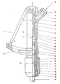
- the tubular body 1 with oxygen supply nozzle 2 and guide and protection 3 for the operating lever 4 is in one piece.
- the oxygen valve generally designated 5, the non-return valve 6, the slag return valve 7 and the clamp holder 8 for the lance tube 9.
- the valves 5, 6 and 7 and the clamp holder 8 can either be used one after the other from an opening in the tubular body 1 or the installations 5, 6, 7, 8 can be installed through both openings of the tubular body 1.
- the valve 5 is inserted through the right opening of the tubular body 1, and the valves 6 and 7 and the clamping bracket 8 are inserted through the left opening of the tubular body 1.
- valve and clamp mounting internals in the tubular body 1 is as follows: By pressing the operating lever 4, which moves in the direction of the tubular body 1, the valve cone 10 becomes against the pressure of the spring 11 in the drawing to the right of it Moved seat and releases the passage for the oxygen flow from the nozzle 2 into the interior of the tubular body 1. As long as the operating lever 4 is actuated, the valve 5 remains in the open position. When the lever 4 is released, the valve cone 10 is returned to the closed position shown in the drawing by relaxing the compression spring 11. A sealing of the valves 5 to the outside is ensured by sealing rings 12, 13.
- the non-return valve 6 opens under the pressure of the oxygen flow when the valve 5 is open and the spring 14 is compressed. If the return flow pressure exceeds the pressure of the supplied oxygen, the non-return valve 6 closes the passage through the tubular body 1 under the action of the spring 14. In the Drawing is the non-return valve 6 in the closed position.
- the slag return check valve 7 consists of a housing 15 in which the valve closing body 16 is under the pressure of the spring 17.
- the pressure position of the spring 17 is held by the pin 18, which is connected to the sieve 20 by soft solder 19.
- the soft solder 19 is melted, the pin 18 loses its hold relative to the sieve 20, and the valve closing body 16 is moved to the left against the valve seat 21 into the closed position by the compression spring 17.
- the clamping bracket 8 for the lance tube 9 consists of a collet 31, which is resiliently mounted in the tubular body 1 against a rubber buffer 22. After the lance tube 9 has been inserted into the opening of the collet 31, the threaded head 23 is screwed onto the tubular body 1. A in the threaded head 23 by means of a roller bearing 24 rotatably mounted pressure sleeve 25 pushes with its conical inner surface when screwing the threaded head 23 onto a correspondingly bevelled outer peripheral surface of the collet 31 and presses it inward against the lance tube 9 until it is clamped. Seals 26, 27, 28 and 29 seal the threaded head 23 from the tubular body 1.
- the slag return check valve 7 with the parts 15 to 21 can be replaced completely as a replacement cartridge in a maintenance-friendly manner.
Claims (2)
Priority Applications (1)
| Application Number | Priority Date | Filing Date | Title |
|---|---|---|---|
| AT80104980T ATE4552T1 (de) | 1979-09-06 | 1980-08-21 | Rohrkoerper fuer sauerstofflanzen. |
Applications Claiming Priority (2)
| Application Number | Priority Date | Filing Date | Title |
|---|---|---|---|
| DE2936022A DE2936022C2 (de) | 1979-09-06 | 1979-09-06 | Rohrkörper für Sauerstofflanzen |
| DE2936022 | 1979-09-06 |
Publications (2)
| Publication Number | Publication Date |
|---|---|
| EP0025151A1 EP0025151A1 (fr) | 1981-03-18 |
| EP0025151B1 true EP0025151B1 (fr) | 1983-08-31 |
Family
ID=6080207
Family Applications (1)
| Application Number | Title | Priority Date | Filing Date |
|---|---|---|---|
| EP80104980A Expired EP0025151B1 (fr) | 1979-09-06 | 1980-08-21 | Corps tubulaire pour lances à oxygène |
Country Status (3)
| Country | Link |
|---|---|
| EP (1) | EP0025151B1 (fr) |
| AT (1) | ATE4552T1 (fr) |
| DE (1) | DE2936022C2 (fr) |
Families Citing this family (1)
| Publication number | Priority date | Publication date | Assignee | Title |
|---|---|---|---|---|
| ATE89035T1 (de) * | 1988-12-02 | 1993-05-15 | Beda Oxygentech Armatur | Kompaktlanze mit rohrverdrehsicherung. |
Family Cites Families (4)
| Publication number | Priority date | Publication date | Assignee | Title |
|---|---|---|---|---|
| DE2327595C2 (de) * | 1973-05-30 | 1974-10-10 | Fa. Manfred Schulz, 4032 Lintorf | Rohrhalter, insbesondere für das Brennrohr einer Sauerstofflanze |
| DE2447723C2 (de) * | 1974-10-07 | 1975-11-13 | Manfred 4032 Lintorf Schulz | Rohrkörper für eine Sauerstofflanze |
| DE7508317U (de) * | 1975-03-15 | 1975-07-10 | Schulz M | Rohrkörper mit angelenktem Bedienungshebel für das Schnellschlußventil einer Sauerstofflanze |
| FR2410678A1 (fr) * | 1977-12-03 | 1979-06-29 | Schulz Manfred | Poignee pour lance a oxygene |
-
1979
- 1979-09-06 DE DE2936022A patent/DE2936022C2/de not_active Expired
-
1980
- 1980-08-21 EP EP80104980A patent/EP0025151B1/fr not_active Expired
- 1980-08-21 AT AT80104980T patent/ATE4552T1/de not_active IP Right Cessation
Also Published As
| Publication number | Publication date |
|---|---|
| EP0025151A1 (fr) | 1981-03-18 |
| ATE4552T1 (de) | 1983-09-15 |
| DE2936022C2 (de) | 1981-11-26 |
| DE2936022B1 (de) | 1981-03-19 |
Similar Documents
| Publication | Publication Date | Title |
|---|---|---|
| DE3229240C2 (de) | Für Überdruckbetrieb geeignetes Atemschutzgerät | |
| DE2351718B2 (de) | Sicherheits- und Warnvorrichtung für den Speisekreis eines Gasverbrauchers | |
| CH672175A5 (fr) | ||
| DE2744917C3 (de) | Sitzventil mit geradem Durchgang | |
| EP0025151B1 (fr) | Corps tubulaire pour lances à oxygène | |
| CH675286A5 (fr) | ||
| EP0629802A1 (fr) | Limiteur de pression équilibré | |
| DE2245399A1 (de) | Ventil, insbesondere zur endlagenumsteuerung von zylinderaggregaten | |
| DE2729305A1 (de) | Rohrtrenner | |
| DE19739845C1 (de) | Prüfvorrichtung für Druckleitungen, insbesondere Gasleitungen | |
| DE3026550C2 (de) | Vorrichtung zum Öffnen und Schließen einer Tür, insbesondere einer Feuertür | |
| DE2244135C3 (fr) | ||
| DE3139376A1 (de) | Schweisselektroden-anordnung mit direkter fluessigkeitskuehlung der elektrodenkappe | |
| EP0044031A1 (fr) | Dispositif d'ouverture ou de fermeture d'une porte, en particulier d'une porte coupe-feu | |
| DE2617721B2 (de) | Steuerventil fur gasförmige und flüssige Medien | |
| DE1045195B (de) | Selbsttaetig wirkende Ventilanordnung zur Steuerung und Drosselung des Zu- bzw. Ruecklaufes eines Druckmittels zu bzw. von einer Arbeitseinrichtung | |
| DE19545640B4 (de) | Steuerventileinrichtung | |
| DE2950640C2 (de) | Kraftstofftank mit Kraftstoffeinfüllrohr, insbesondere für Kraftfahrzeuge | |
| DE2648333C2 (de) | Tränkebeckenventil | |
| DE849215C (de) | Filmfuehrung fuer kinematografische Vorfuehrgeraete | |
| WO1996036741A1 (fr) | Reacteur hermetique sous vide pour le traitement de l'acier, muni d'une douille d'obturation | |
| AT216972B (de) | Verschluß für Druckrohrleitungen | |
| DE2631319A1 (de) | Ventil zum automatischen steuern des durchgangs eines fluids | |
| DE4042546C2 (de) | Wasserdichte und/oder wassergeschützte Kamera | |
| DE3512085A1 (de) | Adapter zur druckminderung, insbesondere bei siphongeraeten |
Legal Events
| Date | Code | Title | Description |
|---|---|---|---|
| PUAI | Public reference made under article 153(3) epc to a published international application that has entered the european phase |
Free format text: ORIGINAL CODE: 0009012 |
|
| AK | Designated contracting states |
Designated state(s): AT BE FR GB IT LU |
|
| 17P | Request for examination filed |
Effective date: 19810912 |
|
| GRAA | (expected) grant |
Free format text: ORIGINAL CODE: 0009210 |
|
| AK | Designated contracting states |
Designated state(s): AT BE FR GB IT LU |
|
| PG25 | Lapsed in a contracting state [announced via postgrant information from national office to epo] |
Ref country code: IT Free format text: LAPSE BECAUSE OF FAILURE TO SUBMIT A TRANSLATION OF THE DESCRIPTION OR TO PAY THE FEE WITHIN THE PRESCRIBED TIME-LIMIT;WARNING: LAPSES OF ITALIAN PATENTS WITH EFFECTIVE DATE BEFORE 2007 MAY HAVE OCCURRED AT ANY TIME BEFORE 2007. THE CORRECT EFFECTIVE DATE MAY BE DIFFERENT FROM THE ONE RECORDED. Effective date: 19830831 |
|
| REF | Corresponds to: |
Ref document number: 4552 Country of ref document: AT Date of ref document: 19830915 Kind code of ref document: T |
|
| ET | Fr: translation filed | ||
| PLBE | No opposition filed within time limit |
Free format text: ORIGINAL CODE: 0009261 |
|
| STAA | Information on the status of an ep patent application or granted ep patent |
Free format text: STATUS: NO OPPOSITION FILED WITHIN TIME LIMIT |
|
| 26N | No opposition filed | ||
| ITTA | It: last paid annual fee | ||
| EPTA | Lu: last paid annual fee | ||
| PGFP | Annual fee paid to national office [announced via postgrant information from national office to epo] |
Ref country code: LU Payment date: 19960801 Year of fee payment: 17 |
|
| PG25 | Lapsed in a contracting state [announced via postgrant information from national office to epo] |
Ref country code: LU Free format text: LAPSE BECAUSE OF NON-PAYMENT OF DUE FEES Effective date: 19970821 |
|
| PGFP | Annual fee paid to national office [announced via postgrant information from national office to epo] |
Ref country code: AT Payment date: 19990729 Year of fee payment: 20 |
|
| PGFP | Annual fee paid to national office [announced via postgrant information from national office to epo] |
Ref country code: FR Payment date: 19990730 Year of fee payment: 20 |
|
| PGFP | Annual fee paid to national office [announced via postgrant information from national office to epo] |
Ref country code: GB Payment date: 19990818 Year of fee payment: 20 |
|
| PGFP | Annual fee paid to national office [announced via postgrant information from national office to epo] |
Ref country code: BE Payment date: 19990901 Year of fee payment: 20 |
|
| BE20 | Be: patent expired |
Free format text: 20000821 *BEDA-OXYGENTECHNIK ARMATUREN G.M.B.H. & CO. K.G. |
|
| PG25 | Lapsed in a contracting state [announced via postgrant information from national office to epo] |
Ref country code: GB Free format text: LAPSE BECAUSE OF EXPIRATION OF PROTECTION Effective date: 20000820 |
|
| PG25 | Lapsed in a contracting state [announced via postgrant information from national office to epo] |
Ref country code: AT Free format text: LAPSE BECAUSE OF EXPIRATION OF PROTECTION Effective date: 20000821 |
|
| REG | Reference to a national code |
Ref country code: GB Ref legal event code: PE20 Effective date: 20000820 |