EP0025151B1 - Tubular holder for oxygen lances - Google Patents
Tubular holder for oxygen lances Download PDFInfo
- Publication number
- EP0025151B1 EP0025151B1 EP80104980A EP80104980A EP0025151B1 EP 0025151 B1 EP0025151 B1 EP 0025151B1 EP 80104980 A EP80104980 A EP 80104980A EP 80104980 A EP80104980 A EP 80104980A EP 0025151 B1 EP0025151 B1 EP 0025151B1
- Authority
- EP
- European Patent Office
- Prior art keywords
- valve
- tubular body
- oxygen
- oxygen lances
- tube
- Prior art date
- Legal status (The legal status is an assumption and is not a legal conclusion. Google has not performed a legal analysis and makes no representation as to the accuracy of the status listed.)
- Expired
Links
- QVGXLLKOCUKJST-UHFFFAOYSA-N atomic oxygen Chemical compound [O] QVGXLLKOCUKJST-UHFFFAOYSA-N 0.000 title claims abstract description 17
- 229910052760 oxygen Inorganic materials 0.000 title claims abstract description 17
- 239000001301 oxygen Substances 0.000 title claims abstract description 17
- 239000002893 slag Substances 0.000 claims abstract description 9
- 230000006835 compression Effects 0.000 description 2
- 238000007906 compression Methods 0.000 description 2
- 238000004519 manufacturing process Methods 0.000 description 2
- 238000007789 sealing Methods 0.000 description 2
- 229910000679 solder Inorganic materials 0.000 description 2
- 238000010276 construction Methods 0.000 description 1
- 230000008030 elimination Effects 0.000 description 1
- 238000003379 elimination reaction Methods 0.000 description 1
- 238000009434 installation Methods 0.000 description 1
- 230000002093 peripheral effect Effects 0.000 description 1
- 230000002040 relaxant effect Effects 0.000 description 1
- 238000009751 slip forming Methods 0.000 description 1
Images
Classifications
-
- B—PERFORMING OPERATIONS; TRANSPORTING
- B23—MACHINE TOOLS; METAL-WORKING NOT OTHERWISE PROVIDED FOR
- B23K—SOLDERING OR UNSOLDERING; WELDING; CLADDING OR PLATING BY SOLDERING OR WELDING; CUTTING BY APPLYING HEAT LOCALLY, e.g. FLAME CUTTING; WORKING BY LASER BEAM
- B23K7/00—Cutting, scarfing, or desurfacing by applying flames
- B23K7/10—Auxiliary devices, e.g. for guiding or supporting the torch
-
- C—CHEMISTRY; METALLURGY
- C21—METALLURGY OF IRON
- C21C—PROCESSING OF PIG-IRON, e.g. REFINING, MANUFACTURE OF WROUGHT-IRON OR STEEL; TREATMENT IN MOLTEN STATE OF FERROUS ALLOYS
- C21C5/00—Manufacture of carbon-steel, e.g. plain mild steel, medium carbon steel or cast steel or stainless steel
- C21C5/28—Manufacture of steel in the converter
- C21C5/42—Constructional features of converters
- C21C5/46—Details or accessories
- C21C5/4606—Lances or injectors
Definitions
- the invention relates to a tubular body for oxygen lances, in which the oxygen valve with the operating mechanism, the non-return valve, the slag non-return valve and the clamp holder for the lance tube are accommodated.
- Tubular bodies for oxygen lances of this type are known with special features of the design of the valve arrangements from DE-PS 2 447 723, DE-PS 2 327 595, DE-GM 7 508 317 and DE-GM 7 438 816.
- To accommodate all valve arrangements and the clamping bracket for the tubular lance are the known tubular bodies for oxygen lances in five or seven parts with four or six connecting points of the tubular body parts.
- the connection points form sources of danger for leaks. Since the oxygen lances are treated very roughly in the company, the connection points must be sealed particularly well, which is associated with considerable constructional and financial expenditure. Despite the effort to ensure that the connection points are properly sealed, they always remain at risk of leakage. The majority of the parts from which the tubular body for oxygen lances is built increases the cost of production and increases the assembly effort when assembling the tubular body.
- the object of the present invention is therefore to provide a tubular body in which the risk of leakage at connection points is reduced, which can be produced in a simple and inexpensive manner, is more manageable due to its light, compact design and does not require any complex assembly.
- a tubular body of the type mentioned is proposed, the portion of the valve arrangement receiving portion with lever protection is continuously formed in one piece.
- the number of connection points at risk of leakage is reduced from four or six, namely the connecting point between the section receiving the valve arrangements and the section of the tubular body containing the clamp holder for the lance tube.
- This division into two is expedient for those applications in which the section containing the clamp for the lance tube is to be expediently interchangeable to adapt to different diameters of the lance tubes. Lances for different lance tube diameters can then be operated with the same valve arrangement. To adapt to the respective lance diameter, only the section of the tube body which receives the lance tube then has to be replaced.
- the inventive design of the tubular body for oxygen lances has the advantages of simple and inexpensive manufacture because only one part has to be manufactured for the tubular body, assembly is simplified because the tubular body no longer has to be composed of different parts, and the result is a light, compact construction, since the length can be reduced to less than half and weight can be saved because of the elimination of the connecting elements between the tubular body sections. This leads to a more manageable design of the tubular body, so that it can be used better even in narrow, difficult to access places than the known, considerably longer tubular body designs.
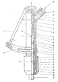
- the tubular body 1 with oxygen supply nozzle 2 and guide and protection 3 for the operating lever 4 is in one piece.
- the oxygen valve generally designated 5, the non-return valve 6, the slag return valve 7 and the clamp holder 8 for the lance tube 9.
- the valves 5, 6 and 7 and the clamp holder 8 can either be used one after the other from an opening in the tubular body 1 or the installations 5, 6, 7, 8 can be installed through both openings of the tubular body 1.
- the valve 5 is inserted through the right opening of the tubular body 1, and the valves 6 and 7 and the clamping bracket 8 are inserted through the left opening of the tubular body 1.
- valve and clamp mounting internals in the tubular body 1 is as follows: By pressing the operating lever 4, which moves in the direction of the tubular body 1, the valve cone 10 becomes against the pressure of the spring 11 in the drawing to the right of it Moved seat and releases the passage for the oxygen flow from the nozzle 2 into the interior of the tubular body 1. As long as the operating lever 4 is actuated, the valve 5 remains in the open position. When the lever 4 is released, the valve cone 10 is returned to the closed position shown in the drawing by relaxing the compression spring 11. A sealing of the valves 5 to the outside is ensured by sealing rings 12, 13.
- the non-return valve 6 opens under the pressure of the oxygen flow when the valve 5 is open and the spring 14 is compressed. If the return flow pressure exceeds the pressure of the supplied oxygen, the non-return valve 6 closes the passage through the tubular body 1 under the action of the spring 14. In the Drawing is the non-return valve 6 in the closed position.
- the slag return check valve 7 consists of a housing 15 in which the valve closing body 16 is under the pressure of the spring 17.
- the pressure position of the spring 17 is held by the pin 18, which is connected to the sieve 20 by soft solder 19.
- the soft solder 19 is melted, the pin 18 loses its hold relative to the sieve 20, and the valve closing body 16 is moved to the left against the valve seat 21 into the closed position by the compression spring 17.
- the clamping bracket 8 for the lance tube 9 consists of a collet 31, which is resiliently mounted in the tubular body 1 against a rubber buffer 22. After the lance tube 9 has been inserted into the opening of the collet 31, the threaded head 23 is screwed onto the tubular body 1. A in the threaded head 23 by means of a roller bearing 24 rotatably mounted pressure sleeve 25 pushes with its conical inner surface when screwing the threaded head 23 onto a correspondingly bevelled outer peripheral surface of the collet 31 and presses it inward against the lance tube 9 until it is clamped. Seals 26, 27, 28 and 29 seal the threaded head 23 from the tubular body 1.
- the slag return check valve 7 with the parts 15 to 21 can be replaced completely as a replacement cartridge in a maintenance-friendly manner.
Landscapes
- Engineering & Computer Science (AREA)
- Chemical & Material Sciences (AREA)
- Manufacturing & Machinery (AREA)
- Materials Engineering (AREA)
- Metallurgy (AREA)
- Organic Chemistry (AREA)
- Mechanical Engineering (AREA)
- Quick-Acting Or Multi-Walled Pipe Joints (AREA)
Abstract
Description
Die Erfindung betrifft einen Rohrkörper für Sauerstofflanzen, in dem das Sauerstoffventil mit Bedienungsmechanismus, das Rückstromsperrventil, das Schlackenrücklaufsperrventil und die Klemmhalterung für das Lanzenrohr untergebracht sind.The invention relates to a tubular body for oxygen lances, in which the oxygen valve with the operating mechanism, the non-return valve, the slag non-return valve and the clamp holder for the lance tube are accommodated.
Rohrkörper für Sauerstofflanzen dieser Art sind mit Besonderheiten der Ausgestaltung der Ventilanordnungen bekannt aus DE-PS 2 447 723, DE-PS 2 327 595, DE-GM 7 508 317 und DE-GM 7 438 816. Zur Unterbringung aller Ventilanordnungen und der Klemmhalterung für die Rohrlanze sind die bekannten Rohrkörper für Sauerstofflanzen fünf- bzw. siebenteilig mit vier bzw. sechs Verbindungsstellen der Rohrkörperteile ausgebildet. Die Verbindungsstellen bilden Gefahrenquellen für Leckagen. Da die Sauerstofflanzen im Betrieb recht unsanft behandelt werden, müssen die Verbindungsstellen besonders gut abgedichtet werden, was mit beträchtlichem konstruktivem und finanziellem Aufwand verbunden ist. Trotz des Bemühens um eine gute Abdichtung der Verbindungsstellen bleiben diese jedoch immer leckagegefährdet. Die Mehrzahl der Teile, aus denen der Rohrkörper für Sauerstofflanzen aufgebaut ist, verteuert die Herstellung und vergrössert den Montageaufwand beim Zusammensetzen des Rohrkörpers.Tubular bodies for oxygen lances of this type are known with special features of the design of the valve arrangements from DE-PS 2 447 723, DE-PS 2 327 595, DE-GM 7 508 317 and DE-GM 7 438 816. To accommodate all valve arrangements and the clamping bracket for the tubular lance are the known tubular bodies for oxygen lances in five or seven parts with four or six connecting points of the tubular body parts. The connection points form sources of danger for leaks. Since the oxygen lances are treated very roughly in the company, the connection points must be sealed particularly well, which is associated with considerable constructional and financial expenditure. Despite the effort to ensure that the connection points are properly sealed, they always remain at risk of leakage. The majority of the parts from which the tubular body for oxygen lances is built increases the cost of production and increases the assembly effort when assembling the tubular body.
Aufgabe der vorliegenden Erfindung ist daher die Schaffung eines Rohrkörpers, bei dem die Leckagegefahr an Verbindungsstellen vermindert wird, der in einfacher und preiswerter Weise herstellbar ist, durch leichte, kompakte Bauweise handlicher ist und keiner aufwendigen Montage bedarf.The object of the present invention is therefore to provide a tubular body in which the risk of leakage at connection points is reduced, which can be produced in a simple and inexpensive manner, is more manageable due to its light, compact design and does not require any complex assembly.
Zur Lösung dieser Aufgabe wird ein Rohrkörper der eingangs genannten Gattung vorgeschlagen, dessen die Ventilanordnungen aufnehmender Abschnitt mit Hebelschutz durchgehend einstückig ausgebildet ist. Durch die erfindungsgemäss einstückige Ausbildung des die Ventilanordnungen aufnehmenden Rohrkörperabschnitts wird die Anzahl der leckagegefährdeten Verbindungsstellen von vier bzw. sechs auf eine reduziert, nämlich die Verbindungsstelle zwischen dem die Ventilanordnungen aufnehmenden Abschnitt und dem die Klemmhalterung für das Lanzenrohr enthaltenden Abschnitt des Rohrkörpers. Diese Zweiteilung ist für solche Anwendungsfälle zweckmässig, bei denen der die Klemmhalterung für das Lanzenrohr enthaltende Abschnitt zur Anpassung an verschiedene Durchmesser der Lanzenrohre zweckmässigerweise auswechselbar sein soll. Mit derselben Ventilanordnung können dann Lanzen für verschiedene Lanzenrohrdurchmesser betrieben werden. Zur Anpassung an den jeweiligen Lanzendurchmesser muss dann lediglich der das Lanzenrohr aufnehmende Abschnitt des Rohrkörpers ausgewechselt werden.To solve this problem, a tubular body of the type mentioned is proposed, the portion of the valve arrangement receiving portion with lever protection is continuously formed in one piece. As a result of the one-piece design of the tubular body section receiving the valve arrangements, the number of connection points at risk of leakage is reduced from four or six, namely the connecting point between the section receiving the valve arrangements and the section of the tubular body containing the clamp holder for the lance tube. This division into two is expedient for those applications in which the section containing the clamp for the lance tube is to be expediently interchangeable to adapt to different diameters of the lance tubes. Lances for different lance tube diameters can then be operated with the same valve arrangement. To adapt to the respective lance diameter, only the section of the tube body which receives the lance tube then has to be replaced.
Für eine bestimmte häufig gebrauchte Lanzenrohrabmessung ist es dagegen zweckmässiger, gemäss einer bevorzugten Ausgestaltung der Erfindung den Rohrkörper insgesamt einstückig auszubilden, wobei neben den Ventilanordnungen auch die Klemmhalterung für das Lanzenrohr in den Rohrkörper einsetzbar ist. In diesem Fall ergibt sich eine noch einfachere, preiswertere und handlichere Ausführung des Rohrkörpers und eine leckagegefährdete Verbindungsstelle ist dann innerhalb des Rohrkörpers nicht mehr vorhanden.For a certain frequently used lance tube dimension, on the other hand, it is more expedient, in accordance with a preferred embodiment of the invention, to design the tube body in one piece as a whole, wherein in addition to the valve arrangements, the clamp holder for the lance tube can also be inserted into the tube body. In this case there is an even simpler, cheaper and more manageable design of the tubular body and a connection point at risk of leakage is then no longer present within the tubular body.
Die erfindungsgemässe Ausführung des Rohrkörpers für Sauerstofflanzen hat neben der Verminderung der Leckagegefahr die Vorteile einer einfachen und preiswerten Herstellung, weil nur noch ein Teil für den Rohrkörper hergestellt werden muss, die Montage vereinfacht sich, weil der Rohrkörper nicht mehr aus verschiedenen Teilen zusammengesetzt werden muss, und es ergibt sich eine leichte kompakte Bauweise, da wegen des Fortfalls der Verbindungselemente zwischen den Rohrkörperabschnitten die Baulänge sich auf weniger als die Hälfte verkürzen und Gewicht einsparen lässt. Dies führt zu einer handlicheren Ausführung des Rohrkörpers, so dass er auch an engen schwer zugänglichen Stellen besser zum Einsatz gebracht werden kann als die bekannten erheblich längeren Rohrkörperausführungen.In addition to reducing the risk of leakage, the inventive design of the tubular body for oxygen lances has the advantages of simple and inexpensive manufacture because only one part has to be manufactured for the tubular body, assembly is simplified because the tubular body no longer has to be composed of different parts, and the result is a light, compact construction, since the length can be reduced to less than half and weight can be saved because of the elimination of the connecting elements between the tubular body sections. This leads to a more manageable design of the tubular body, so that it can be used better even in narrow, difficult to access places than the known, considerably longer tubular body designs.
Anhand des in der Zeichnung dargestellten Ausführungsbeispiels wird die Erfindung näher erläutert.On the basis of the embodiment shown in the drawing, the invention is explained in more detail.
Bei dem dargestellten Ausführungsbeispiel ist der Rohrkörper 1 mit Sauerstoffzuführungsstutzen 2 sowie Führung und Schutz 3 für den Bedienungshebel 4 durchgehend einstückig. An Einbauten enthält er das allgemein mit 5 bezeichnete Sauerstoffventil, das Rückstromsperrventil 6, das Schlackenrücklaufsperrventil 7 sowie die Klemmhalterung 8 für das Lanzenrohr 9. Die Ventile 5, 6 und 7 sowie die Klemmhalterung 8 können entweder von einer Öffnung des Rohrkörpers 1 aus nacheinander eingesetzt werden oder die Einbauen 5, 6, 7, 8 können durch beide Öffnungen des Rohrkörpers 1 eingebaut werden. Im dargestellten Ausführungsbeispiel ist das Ventil 5 durch die rechte Öffnung des Rohrkörpers 1 eingesetzt, und die Ventile 6 und 7 sowie die Klemmhalterung 8 sind durch die linke Öffnung des Rohrkörpers 1 eingesetzt.In the illustrated embodiment, the
Die Funktionsweise der Ventil- und Klemmhalterungseinbauten in dem Rohrkörper 1 ist wie folgt: Durch Druck auf den Bedienungshebel 4, der sich dabei in Richtung auf den Rohrkörper 1 bewegt, wird der Ventilkegel 10 gegen den Druck der Feder 11 in der Zeichnung nach rechts von seinem Sitz wegbewegt und gibt den Durchlass für den Sauerstoffstrom aus dem Stutzen 2 in das Innere des Rohrkörpers 1 frei. Solange der Bedienungshebel 4 betätigt wird, bleibt das Ventil 5 in der Öffnungsstellung. Beim Loslassen des Hebels 4 wird der Ventilkegel 10 durch die Entspannung der Druckfeder 11 in seine in der Zeichnung dargestellten Schliessstellung zurückgeführt. Durch Dichtringe 12, 13 ist eine Abdichtung der Ventile 5 nach aussen sichergestellt.The functioning of the valve and clamp mounting internals in the
Das Rückstromsperrventil 6 öffnet sich unter dem Druck des Sauerstoffstroms bei offenem Ventil 5 unter Zusammendrückung der Feder 14. Übersteigt bei einer Rückströmung der Rückströmdruck den Druck des zugeführten Sauerstoffs, so schliesst das Rückstromsperrventil 6 unter der Wirkung der Feder 14 den Durchgang durch den Rohrkörper 1. In der Zeichnung befindet sich das Rückstromsperrventil 6 in der Schliessstellung.The
Das Schlackenrücklaufsperrventil 7 besteht aus einem Gehäuse 15, in dem der Ventilschliesskörper 16 unter dem Druck der Feder 17 steht. Die Druckstellung der Feder 17 wird durch den Stift 18 gehalten, der durch Weichlot 19 mit dem Sieb 20 verbunden ist. Bei Rücklauf heisser Schlacke wird das Weichlot 19 aufgeschmolzen, der Stift 18 verliert seinen Halt gegenüber dem Sieb 20 und durch die Druckfeder 17 wird der Ventilschliesskörper 16 nach links gegen den Ventilsitz 21 in die Schliessstellung verschoben.The slag
Die Klemmhalterung 8 für das Lanzenrohr 9 besteht aus einer Spannzange 31, die gegen einen Gummipuffer 22 nachgiebig in dem Rohrkörper 1 gelagert ist. Nach dem Einschieben des Lanzenrohrs 9 in die Öffnung der Spannzange 31 wird der Gewindekopf 23 auf den Rohrkörper 1 aufgeschraubt. Eine in dem Gewindekopf 23 mittels eines Wälzlagers 24 drehbar gelagerte Druckhülse 25 schiebt sich mit ihrer konischen Innenfläche beim Aufschrauben des Gewindekopfes 23 auf eine entsprechend abgeschrägte Aussenumfangsfläche der Spannzange 31 und drückt diese dabei nach innen gegen das Lanzenrohr 9, bis dieses festgeklemmt ist. Dichtungen 26, 27, 28 und 29 bewirken eine Abdichtung des Gewindekopfes 23 gegenüber dem Rohrkörper 1.The
Im Fall von Schlackerücklauf, der zu einer Schliessung des Schlackenrücksperrventils 7 führt und dieses für weitere Verwendung unbrauchbar macht, kann das Schlackenrücklaufsperrventil 7 mit den Teilen 15 bis 21 komplett als Wechselpatrone wartungsfreundlich ausgetauscht werden.In the case of slag return, which leads to a closure of the
Claims (2)
Priority Applications (1)
| Application Number | Priority Date | Filing Date | Title |
|---|---|---|---|
| AT80104980T ATE4552T1 (en) | 1979-09-06 | 1980-08-21 | TUBE BODY FOR OXYGEN LANCES. |
Applications Claiming Priority (2)
| Application Number | Priority Date | Filing Date | Title |
|---|---|---|---|
| DE2936022A DE2936022C2 (en) | 1979-09-06 | 1979-09-06 | Tube body for oxygen lances |
| DE2936022 | 1979-09-06 |
Publications (2)
| Publication Number | Publication Date |
|---|---|
| EP0025151A1 EP0025151A1 (en) | 1981-03-18 |
| EP0025151B1 true EP0025151B1 (en) | 1983-08-31 |
Family
ID=6080207
Family Applications (1)
| Application Number | Title | Priority Date | Filing Date |
|---|---|---|---|
| EP80104980A Expired EP0025151B1 (en) | 1979-09-06 | 1980-08-21 | Tubular holder for oxygen lances |
Country Status (3)
| Country | Link |
|---|---|
| EP (1) | EP0025151B1 (en) |
| AT (1) | ATE4552T1 (en) |
| DE (1) | DE2936022C2 (en) |
Families Citing this family (1)
| Publication number | Priority date | Publication date | Assignee | Title |
|---|---|---|---|---|
| DE3880841D1 (en) * | 1988-12-02 | 1993-06-09 | Beda Oxygentech Armatur | COMPACT LANCE WITH TUBE TORQUE PROTECTION. |
Family Cites Families (4)
| Publication number | Priority date | Publication date | Assignee | Title |
|---|---|---|---|---|
| DE2327595C2 (en) * | 1973-05-30 | 1974-10-10 | Fa. Manfred Schulz, 4032 Lintorf | Tube holder, especially for the combustion tube of an oxygen lance |
| DE2447723C2 (en) * | 1974-10-07 | 1975-11-13 | Manfred 4032 Lintorf Schulz | Tube body for an oxygen lance |
| DE7508317U (en) * | 1975-03-15 | 1975-07-10 | Schulz M | Tubular body with articulated operating lever for the quick-closing valve of an oxygen lance |
| FR2410678A1 (en) * | 1977-12-03 | 1979-06-29 | Schulz Manfred | HANDLE FOR OXYGEN LANCE |
-
1979
- 1979-09-06 DE DE2936022A patent/DE2936022C2/en not_active Expired
-
1980
- 1980-08-21 AT AT80104980T patent/ATE4552T1/en not_active IP Right Cessation
- 1980-08-21 EP EP80104980A patent/EP0025151B1/en not_active Expired
Also Published As
| Publication number | Publication date |
|---|---|
| ATE4552T1 (en) | 1983-09-15 |
| EP0025151A1 (en) | 1981-03-18 |
| DE2936022B1 (en) | 1981-03-19 |
| DE2936022C2 (en) | 1981-11-26 |
Similar Documents
| Publication | Publication Date | Title |
|---|---|---|
| DE3229240C2 (en) | Breathing apparatus suitable for overpressure operation | |
| DE2351718B2 (en) | Safety and warning device for the supply circuit of a gas consumer | |
| CH672175A5 (en) | ||
| DE2744917C3 (en) | Seat valve with straight passage | |
| EP0025151B1 (en) | Tubular holder for oxygen lances | |
| CH675286A5 (en) | ||
| DE3437737A1 (en) | VALVE | |
| EP0629802A1 (en) | Compensated pressure control valve | |
| DE2245399A1 (en) | VALVE, IN PARTICULAR FOR REVOLVING THE END POSITION OF CYLINDER UNITS | |
| DE2729305A1 (en) | Blocking valve for protecting drinking water pipes - has piston preventing sucking back of dirty water on pressure changes | |
| DE3026550C2 (en) | Device for opening and closing a door, in particular a fire door | |
| DE2244135C3 (en) | ||
| DE3139376A1 (en) | Welding electrode arrangement with direct liquid cooling of the electrode cap | |
| EP0044031A1 (en) | Device for opening or closing a door, especially a fire-door | |
| DE2617721B2 (en) | Control valve for gaseous and liquid media | |
| DE1045195B (en) | Self-acting valve arrangement for controlling and throttling the inflow and return of a pressure medium to or from a working device | |
| DE19545640B4 (en) | Control valve means | |
| DE2950640C2 (en) | Fuel tank with fuel filler pipe, in particular for motor vehicles | |
| DE2648333C2 (en) | Drinking bowl valve | |
| DE849215C (en) | Film guide for cinematographic demonstrators | |
| WO1996036741A1 (en) | Vacuumtight reaction vessel for steel processing with a packing gland | |
| AT216972B (en) | Closure for pressure pipelines | |
| DE3404219A1 (en) | Valve | |
| DE2631319A1 (en) | Automatic fluid control valve - has device for tensioning valve unit away from seat is second chamber pressure is excessive | |
| DE3512085A1 (en) | ADAPTER FOR PRESSURE REDUCTION, ESPECIALLY WITH SIPHONE DEVICES |
Legal Events
| Date | Code | Title | Description |
|---|---|---|---|
| PUAI | Public reference made under article 153(3) epc to a published international application that has entered the european phase |
Free format text: ORIGINAL CODE: 0009012 |
|
| AK | Designated contracting states |
Designated state(s): AT BE FR GB IT LU |
|
| 17P | Request for examination filed |
Effective date: 19810912 |
|
| GRAA | (expected) grant |
Free format text: ORIGINAL CODE: 0009210 |
|
| AK | Designated contracting states |
Designated state(s): AT BE FR GB IT LU |
|
| PG25 | Lapsed in a contracting state [announced via postgrant information from national office to epo] |
Ref country code: IT Free format text: LAPSE BECAUSE OF FAILURE TO SUBMIT A TRANSLATION OF THE DESCRIPTION OR TO PAY THE FEE WITHIN THE PRESCRIBED TIME-LIMIT;WARNING: LAPSES OF ITALIAN PATENTS WITH EFFECTIVE DATE BEFORE 2007 MAY HAVE OCCURRED AT ANY TIME BEFORE 2007. THE CORRECT EFFECTIVE DATE MAY BE DIFFERENT FROM THE ONE RECORDED. Effective date: 19830831 |
|
| REF | Corresponds to: |
Ref document number: 4552 Country of ref document: AT Date of ref document: 19830915 Kind code of ref document: T |
|
| ET | Fr: translation filed | ||
| PLBE | No opposition filed within time limit |
Free format text: ORIGINAL CODE: 0009261 |
|
| STAA | Information on the status of an ep patent application or granted ep patent |
Free format text: STATUS: NO OPPOSITION FILED WITHIN TIME LIMIT |
|
| 26N | No opposition filed | ||
| ITTA | It: last paid annual fee | ||
| EPTA | Lu: last paid annual fee | ||
| PGFP | Annual fee paid to national office [announced via postgrant information from national office to epo] |
Ref country code: LU Payment date: 19960801 Year of fee payment: 17 |
|
| PG25 | Lapsed in a contracting state [announced via postgrant information from national office to epo] |
Ref country code: LU Free format text: LAPSE BECAUSE OF NON-PAYMENT OF DUE FEES Effective date: 19970821 |
|
| PGFP | Annual fee paid to national office [announced via postgrant information from national office to epo] |
Ref country code: AT Payment date: 19990729 Year of fee payment: 20 |
|
| PGFP | Annual fee paid to national office [announced via postgrant information from national office to epo] |
Ref country code: FR Payment date: 19990730 Year of fee payment: 20 |
|
| PGFP | Annual fee paid to national office [announced via postgrant information from national office to epo] |
Ref country code: GB Payment date: 19990818 Year of fee payment: 20 |
|
| PGFP | Annual fee paid to national office [announced via postgrant information from national office to epo] |
Ref country code: BE Payment date: 19990901 Year of fee payment: 20 |
|
| BE20 | Be: patent expired |
Free format text: 20000821 *BEDA-OXYGENTECHNIK ARMATUREN G.M.B.H. & CO. K.G. |
|
| PG25 | Lapsed in a contracting state [announced via postgrant information from national office to epo] |
Ref country code: GB Free format text: LAPSE BECAUSE OF EXPIRATION OF PROTECTION Effective date: 20000820 |
|
| PG25 | Lapsed in a contracting state [announced via postgrant information from national office to epo] |
Ref country code: AT Free format text: LAPSE BECAUSE OF EXPIRATION OF PROTECTION Effective date: 20000821 |
|
| REG | Reference to a national code |
Ref country code: GB Ref legal event code: PE20 Effective date: 20000820 |